When you click on links to various merchants on this site and make a purchase, this can result in this site earning a commission. Affiliate programs and affiliations include, but are not limited to, the eBay Partner Network.
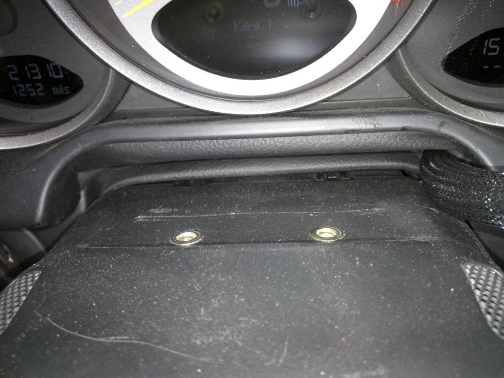
Okay, I found the correct twisted pair inside the bundle near the fusebox location. Still looking under radio. Now the dilemma is how to mount the MXS without butchering anything and getting the connection wiring where it can be disconnected and harness removed for the occasional road trip. Any ideas??
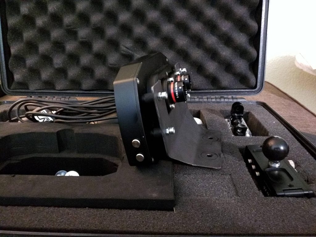
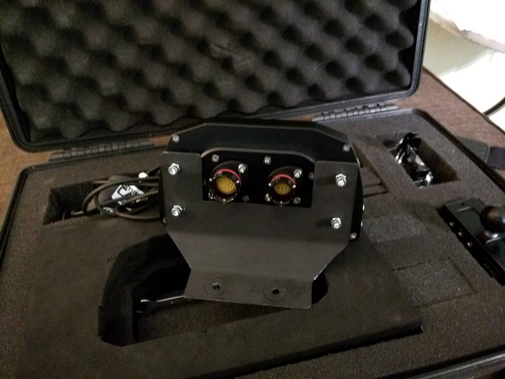
great! tcd fabbed the bracket for my mxs, here are some photos. i move the unit between my miata with 8mm hex bolt. you can see the primary harness sticking out of the top right in the first phot
Thanks much. A great location. Couple of questions regarding connectors. When mounted, are the connectors on the back of the MXS near the instrument bezels?
Is your steering column pulled all the way out to the max extension? I have short legs and therefore the column is all the way in when I am strapped in the seat. Maybe able to make it work by stripping shrink tubing from harness to allow more room behind MXS. Again thanks to everyone..
the connector is right up next to the cluster, next time i mount the dash ill take a pic for you
i'll check my steering column tonight, i'm pretty sure i am able to adjust it without any problems.
one issue i did run into was the harness shrink wrap was really thick. luckily, i have two harnesses, and one of them is using a flex loom that worked better in the gt3. the miata harness is literally a rod of wires
The shrink wrap on mine I cut off to the 90 but it is still too far out. I believe I will cut the 90 portion off then put a mesh sleeve over it and see how that works. I called TCD to see if they still had a pattern but they don't. I will make mine from 3/16 aluminum and have it powder coated. Then rivnuts to upper column cover so it can be removed. Thanks for the help. If you ever get down to New Orleans ping me and I'll buy you dinner or a drink.
The shrink wrap on mine I cut off to the 90 but it is still too far out. I believe I will cut the 90 portion off then put a mesh sleeve over it and see how that works. I called TCD to see if they still had a pattern but they don't. I will make mine from 3/16 aluminum and have it powder coated. Then rivnuts to upper column cover so it can be removed. Thanks for the help. If you ever get down to New Orleans ping me and I'll buy you dinner or a drink.
awesome, excited to see how it turns out!
double check the clearance between the harness and the gauge cluster as well as the steering wheel and the front of the dash
A different way to go, if you are still looking for options....
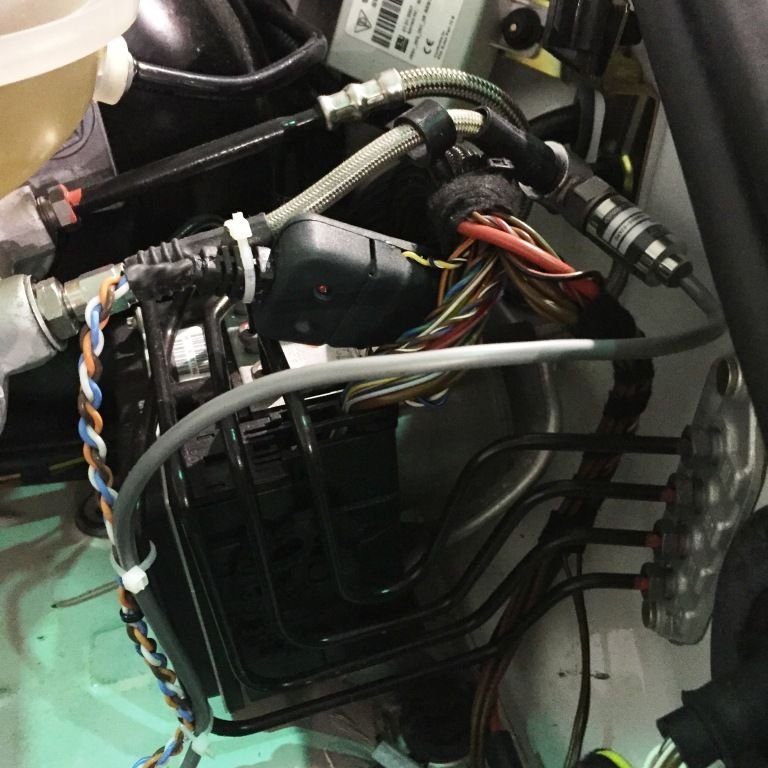
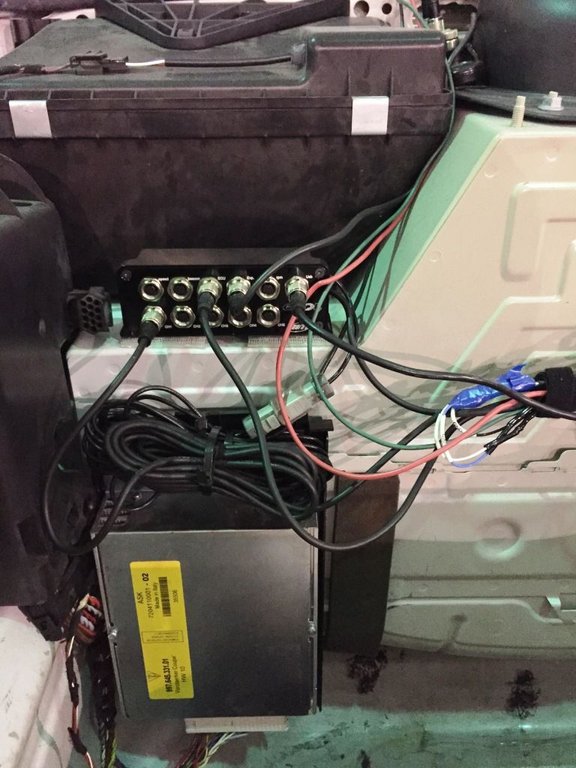
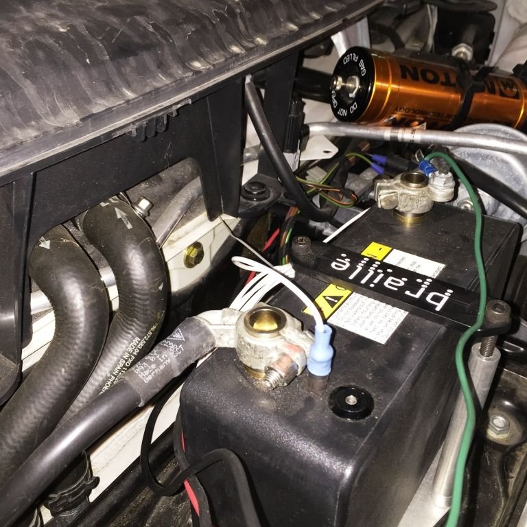
I took the CAN off the connection at the ABS/PSM module in the frunk. I also am taking brake pressure there, knowing I might want to go 4 channel on that in the future, plus steering is there (if I do not like the steering angle on CAN for some reason), and easy access to the front suspension for shock pots.
The lines run to the EVO 4 in the frunk:
Lines for the dash and smartycam then go thru the firewall and into the cabin through the opening behind the battery (a round, sticky piece of foam you can peel up):
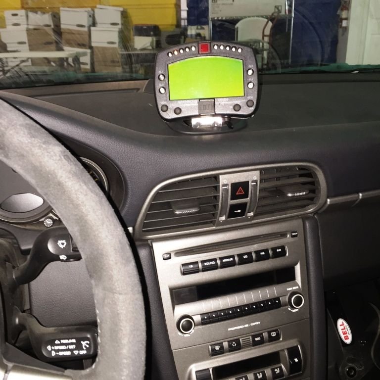
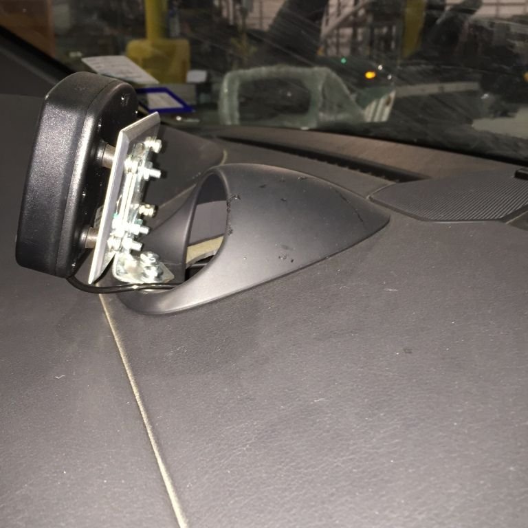
They enter high behind the dash, with easy access to the wart. The wart snaps off. I bought an additional wart (about $90) and fastened the dash to it. The camera line snakes through the transmission hump back to the roll cage mounting:
Side view:
You can snap off the dash and unscrew the connectors for easy removal, snap the chrono back in if you are going on a date...
Thanks for this info. My GT3 is a 2007, so only has ABS/TC and I am not sure the TC works (don't care) as I never see the lights activate. I was thinking of the wart as a place to route the wires through after fabbing a mount for the dash. But this is a great second option if the steering mount doesn't work out. The passage to the frunk is good to know as it will provide access to place the GPS antenna under the lower windshield plastic trim near the wipers. Again thanks for all of the ideas and help.
gps under the trim up front works well, if you want to make it a little easier to remove everything from your car just toss the antenna in the back behind the rollbar and give it line of sight. i have my expander back there as well so i can plug in the smarty cam and the gps at the same time
Finally finished fabricating a bracket that will work for my short legs. Steering column bracket wouldn't allow proper positioning of wheel for my driving position. It wouldn't go completely forward where my feet could reach the pedals(rather important) as the AIM harness connector was contacting the instrument panel face. I used a Proclip vent mount for cell phones with a quick release slide mechanism mounted to the fabricated aluminum bracket. This bracket bends ove the dash and extends to the wart, where I put a 4mm nutsert in the section ahead of the useless timer face. Then a 4mm thumbscrew retains the horizontal portion, preventing the slide of the quick release from moving up and out. I will post pics when I can figure out how to get them right side up.


 07-20-2015 | 01:50 AM