When you click on links to various merchants on this site and make a purchase, this can result in this site earning a commission. Affiliate programs and affiliations include, but are not limited to, the eBay Partner Network.
I'm in the process of making a tow strap setup from the GT4CS strap P/N 981 722 695 8A to fit a 997 GT3/RS.
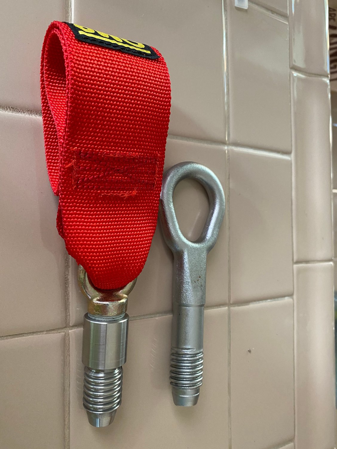
I know that there are a variety of tow hooks available for the 997 and I just don't like them in comparison to the factory Tow hook. I found a company that does make a tow strap version, but it doesn't have the detail of the OMP strap with the hook and loop velcro and I wasn't a fan of the design of their threaded stud. So I decided I will purchase the GT4CS tow strap and see if I can create my own. I understand that this won't be a cheaper alternative, but the project goal is to create something that is equivalent or better to the factory CS strap.
Below is a list of my design issues with that product:
1. I'm not fan of the strap material (seat belt)
2. I also don't like the rectangular/square end, I do believe it protrudes out side of the bumper, which makes it more visible than the eyebolt
3. No velcro to keep the strap folded up
4. It's not OMP/porsche motorsports
Agreed on all. Maybe it�s a decent stop gap product until yours is ready 😉
Apologies for the delayed update. Thanks to Coop for the nudge to post.
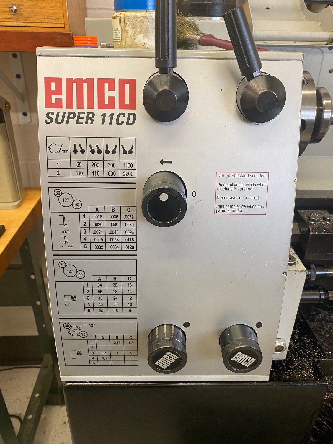
I had more issues than I thought I would have machining this thread. I've machined plenty of threads (internal and external), but this one is special. I have a manual lathe with auto feed and in order to machine a thread you need to set the feed rate (revolutions per inch, also known as the thread pitch). In this case we are machining a DIN 405, Rd 20 x 1/8, which means the thread pitch is 8 threads per inch. Given that I have an EMCO lathe, which is made in Austria, but spec'd as a US machine for inches, I figured this shouldn't be a problem, 8 threads per inch would seem common. Well it's not.
Below in the image are the standard pitches on the machine. If you look hard enough in columns A, B and C you will not find 8 threads per inch.
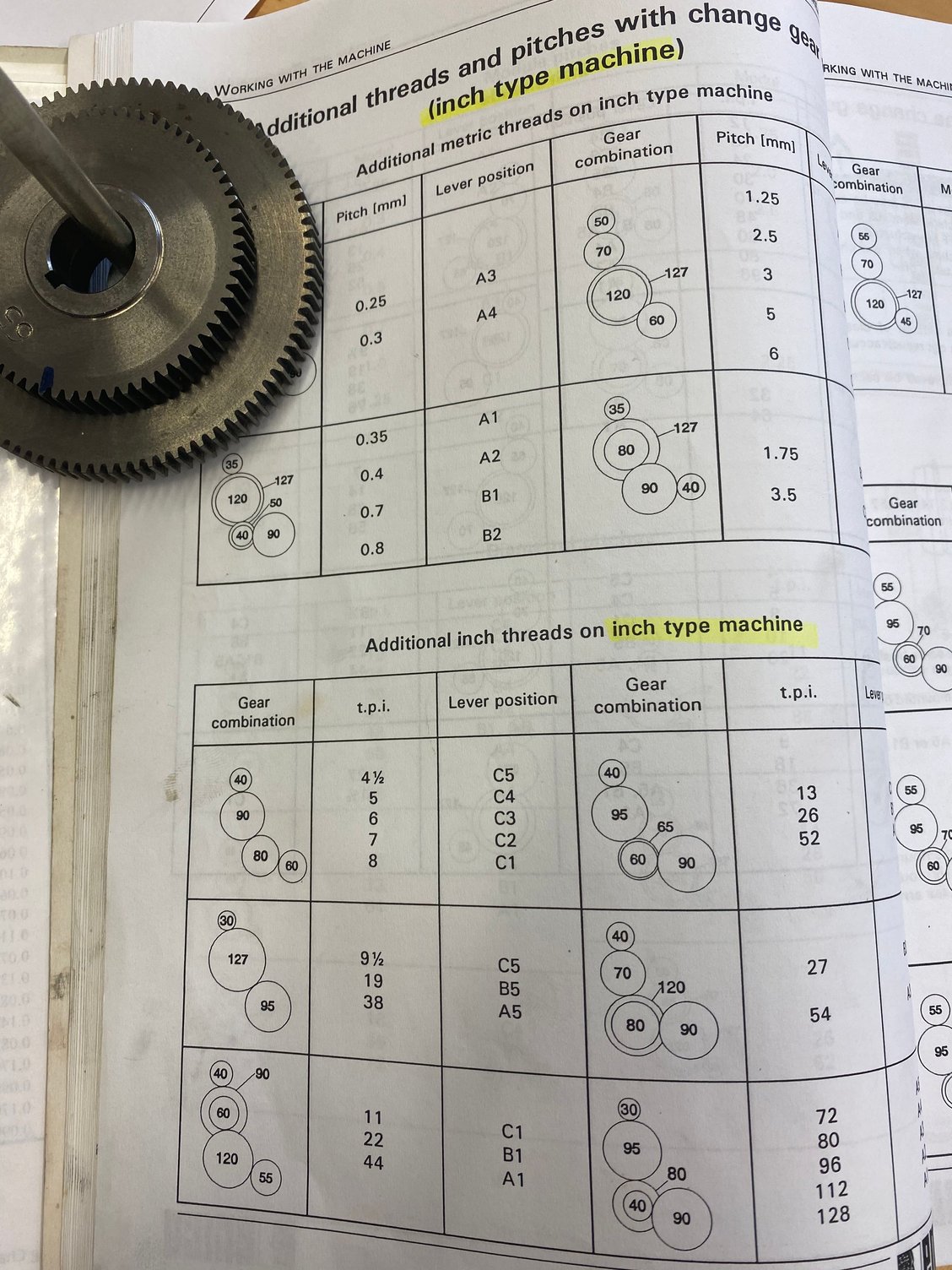
So the next step is to find the correct gear set in the lathe manual and then install the change gears to achieve the correction turns per inch. Fortunately, I have all of the change gears for this machine. Unfortunately, I took me three times to cut the correct thread. The first time I spaced out and thought the machine was magically set at 8, but it was set at 9 threads per inch. Visibly the thread profile was wrong. The second time, when I was referencing the manual for the change gears I referenced the gears associated with the Metric type machine, so that when I installed the gears and cut the thread it obviously didn't look right and I took me some time to figure out that I need to flip through a couple more pages in the manual to get to Inch type machine. The third time around I got it all dialed in. Nonetheless, this was several attempts at machining this one part, which should've been very straight forward. Each failure at least 2-3hrs of work. Let alone the thinking time of why it was wrong.
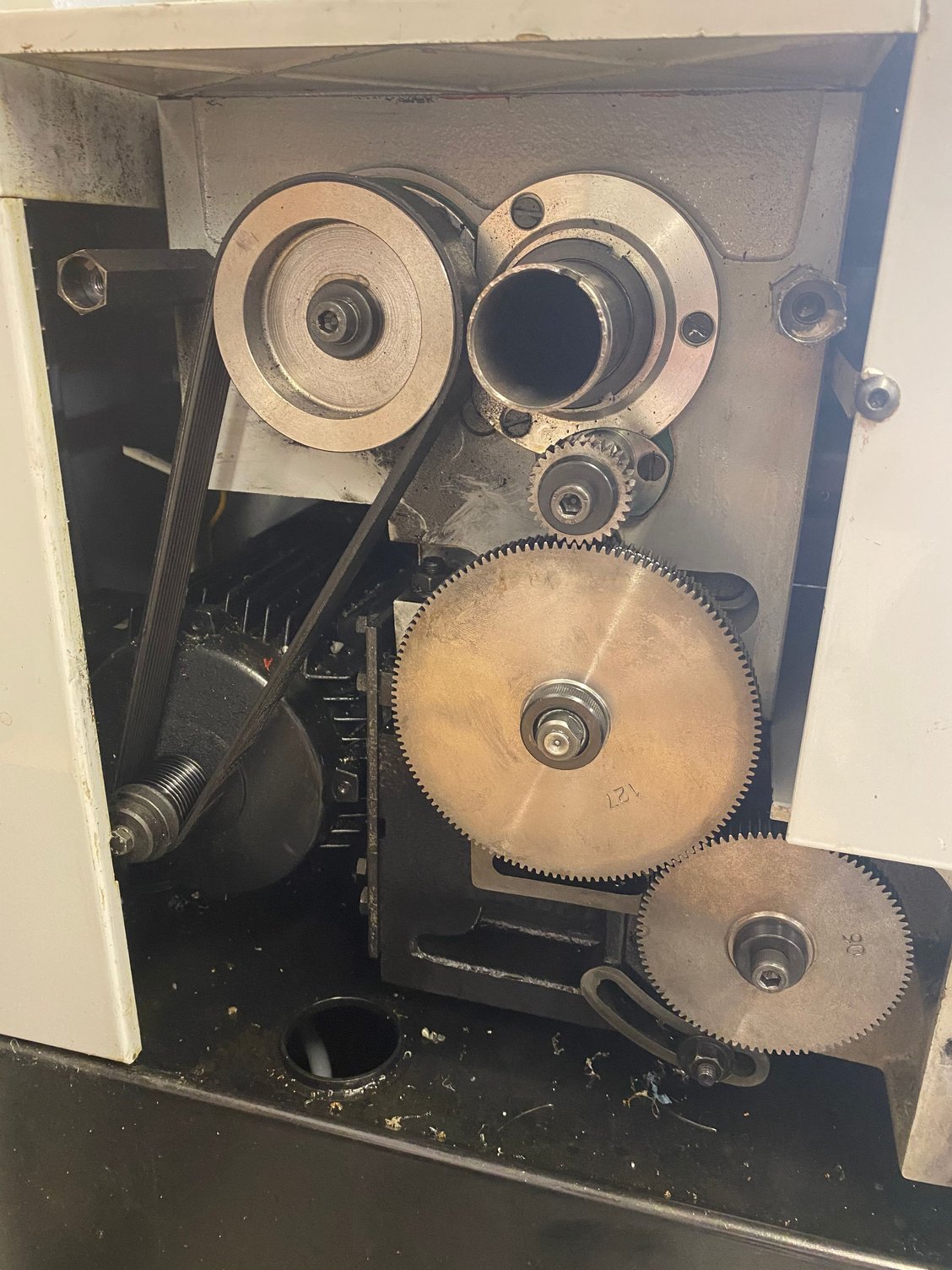
Normal everyday gear setup as shown on the machine (cover removed)
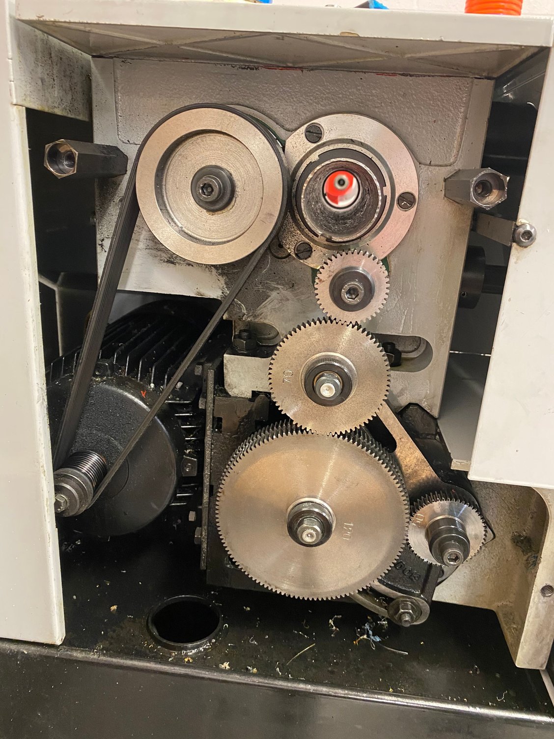
Setup with change gears for 8 threads per inch.
OK, now that this was all figured out. Below are some of the steps that I captured.
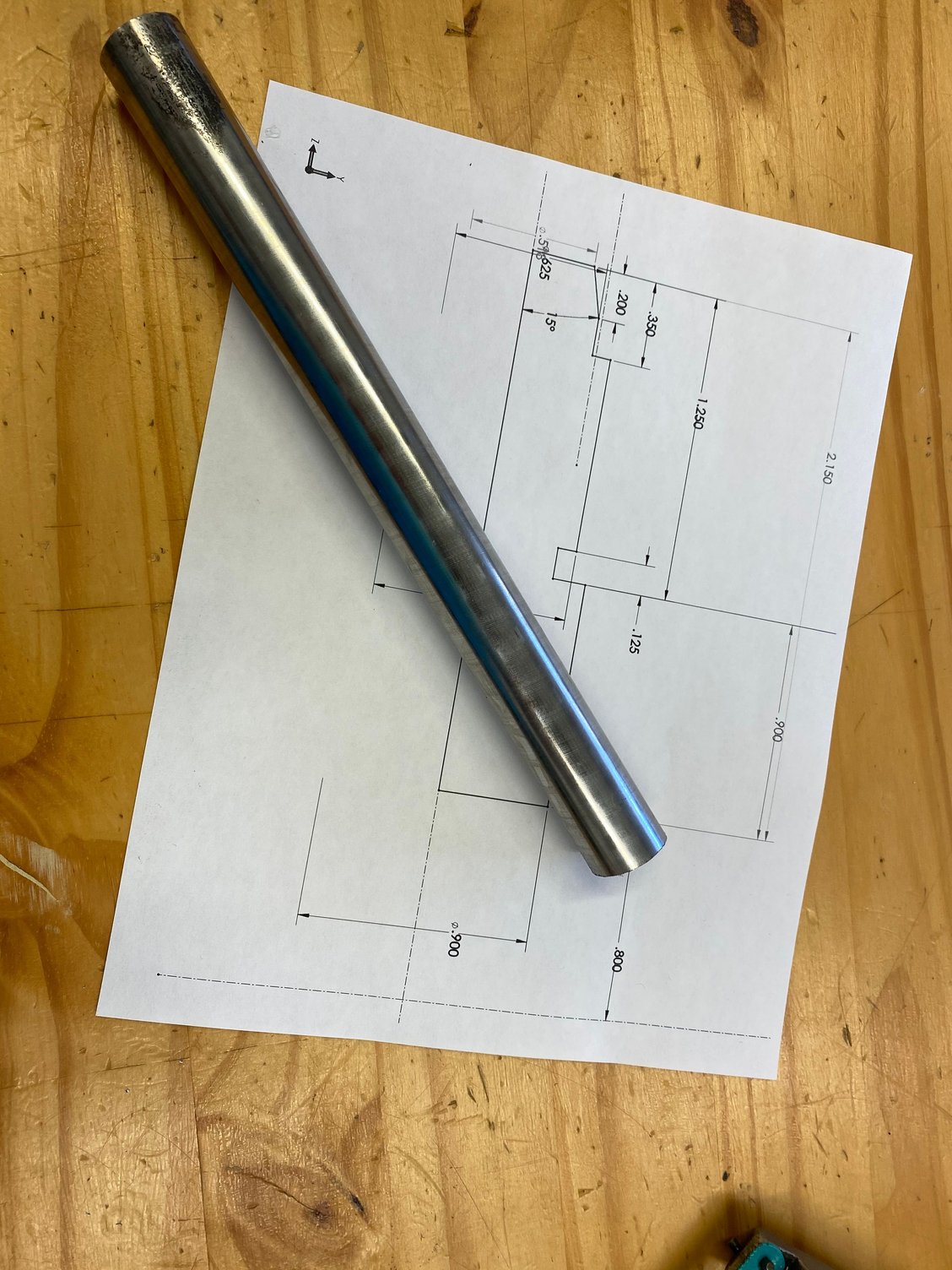
A sketch with dimensions and the raw material. I always find it amazing to start with raw material and create something out of nothing.
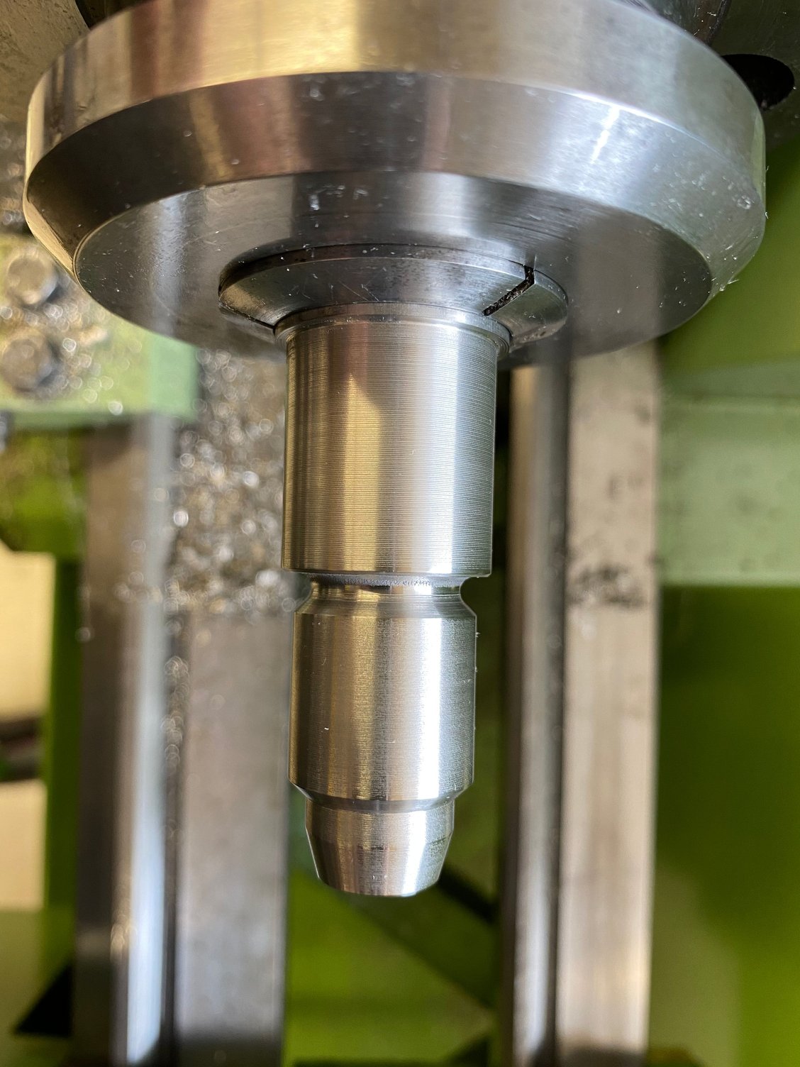
Yes, image below is on a a different lathe. Since I setup the gears on one lathe, I ended up machining the blank on the other lathe. Yes, machine marks and chatter are visible, but I cleaned those up later.
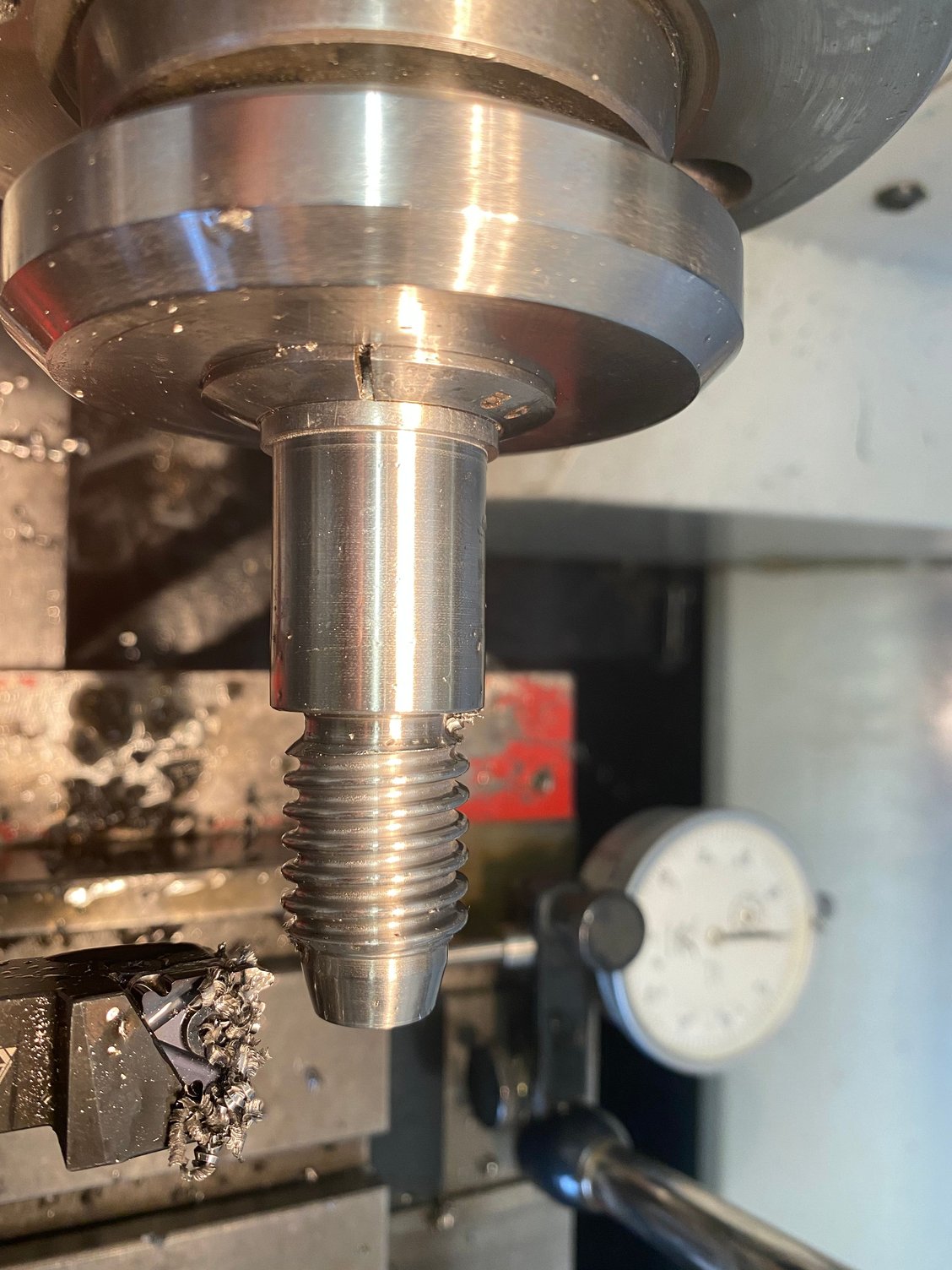
And just like magic the threads are cut. Thread cutting on a "manual" lathe like this is time consuming and tedious. You're literally removing .001-.002in per cut in stainless steel and since this thread is so deep it took forever. Furthermore, I had nothing to check this thread with (no profile gauge or nut), just a comparison to the OEM thread.
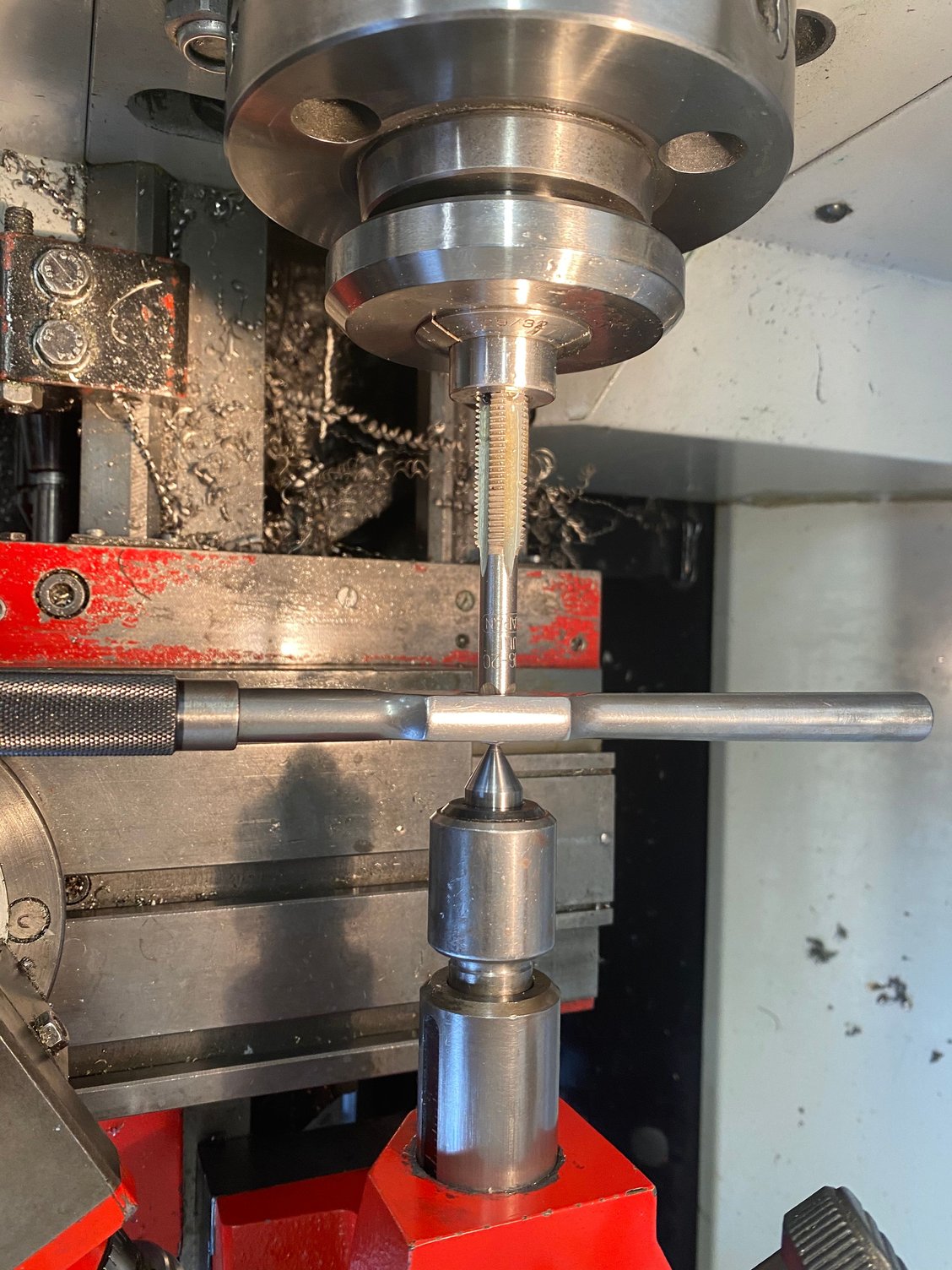
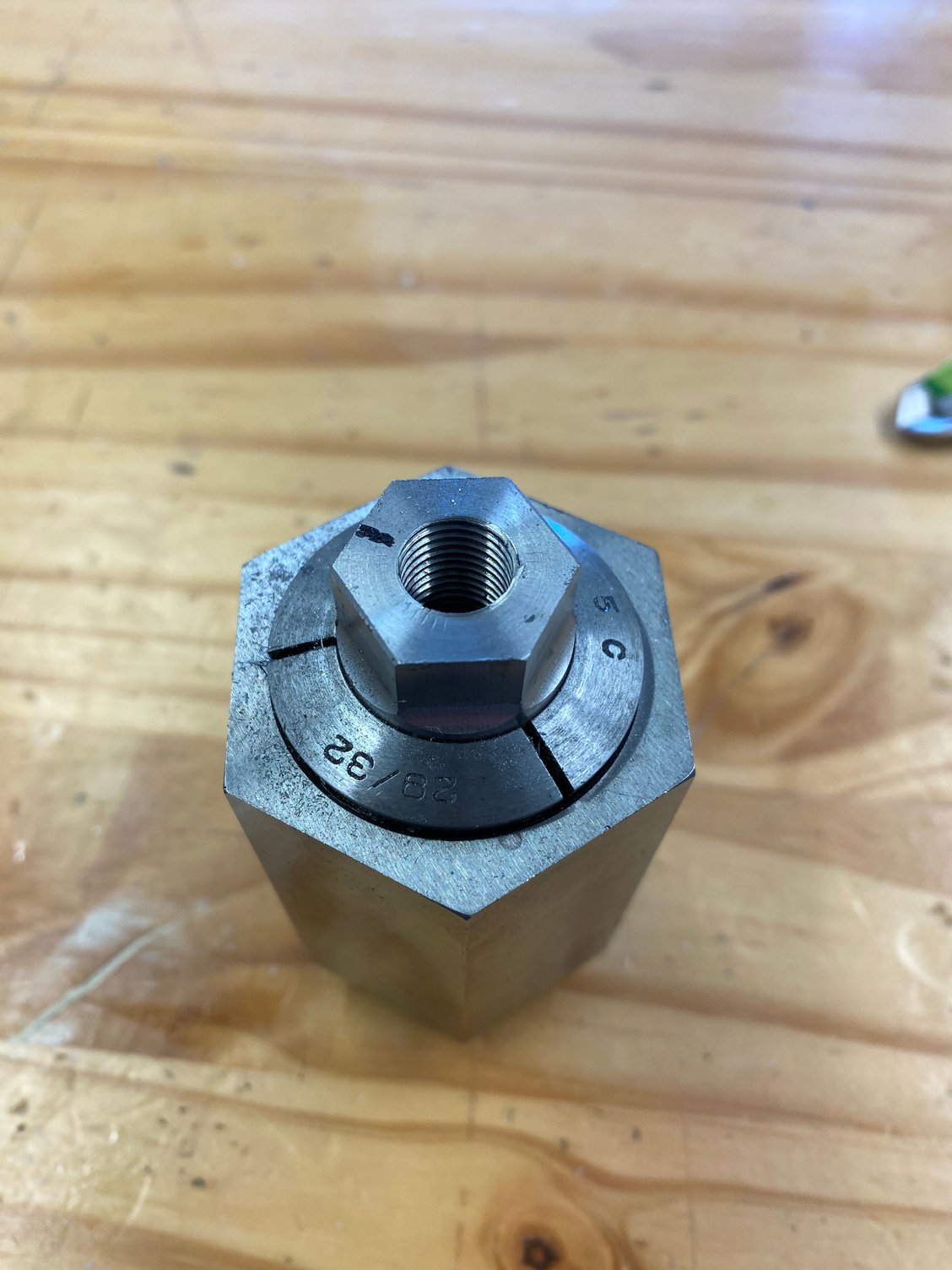
Flipped the part around and drilled and tapped for the 7/16-20 eye bolt. Manual tapping shown below.
At this point I wanted to make sure everything would fit, so I didn't do any of the mill work.
Fortunately (as designed and machined) everything went together, but the clocking was off as anticipated. I went back and forth a couple of times further reducing the length of the shoulder until I got the Eyebolt seated where I thought it was acceptable (enough room to tighten and not stick out too far and have enough room for the strap to move on angle without rubbing on the bumper skin.
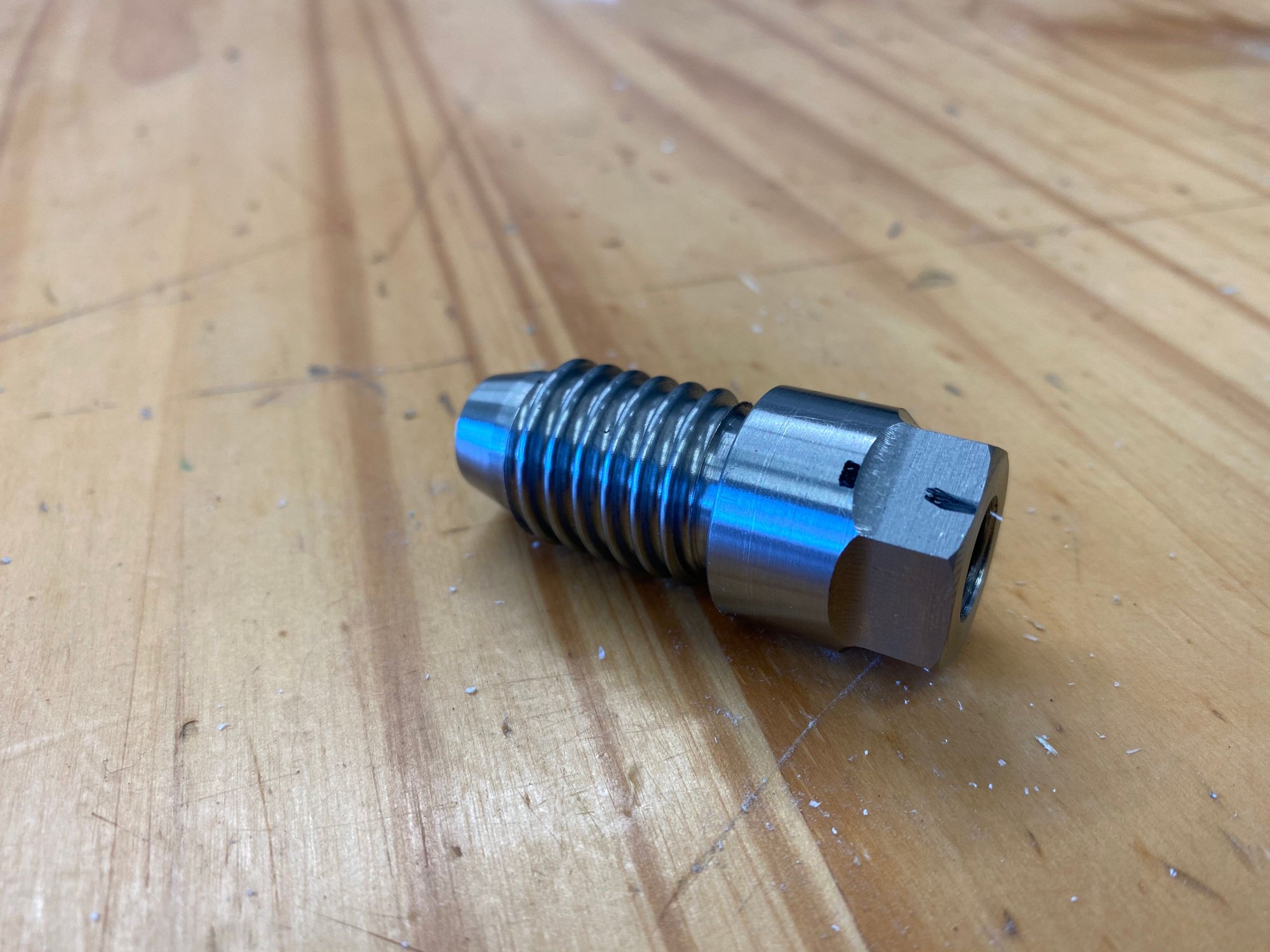
Once I got the final length dialed in, I machined 2 flats at 180�, which are need for tightening the Eyebolt to the Adapter. During one test fit, I was able tighten the adapter to the car more than the bolt to the adapter. During the removal the bolt/strap unthreaded with the adapter buried behind the bumper. So once I got the adapter out (it wasn't that tight) with some needle nose pliers, I decided to machine a hex so that in any case you could get a socket on the adapter for removal, without the need to remove the bumper skin.
All machined up. DIN 405 Rd20x1/8 with an 19mm hex. I haven't actually fully torqued/loctited the adapter/bolt assembly together yet and therefore, I don't have a pic of the final assembly, but I'm sure you can imagine what it looks like.
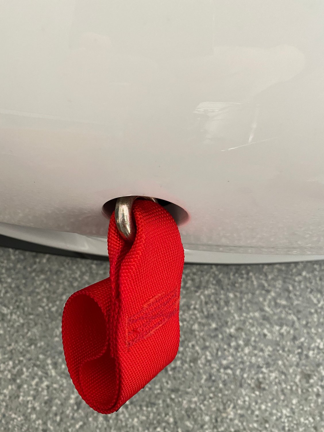
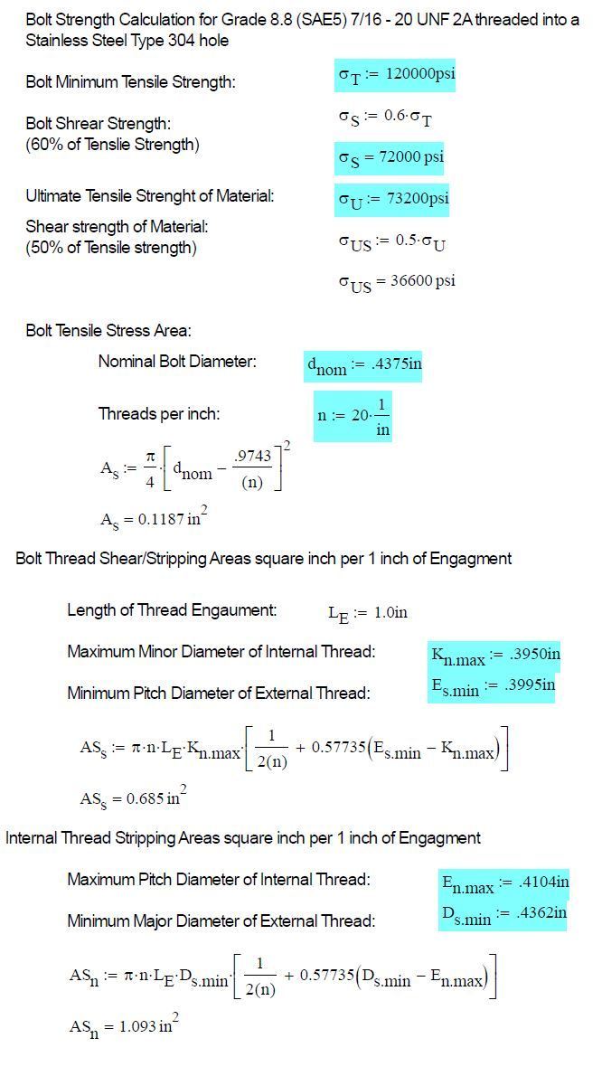
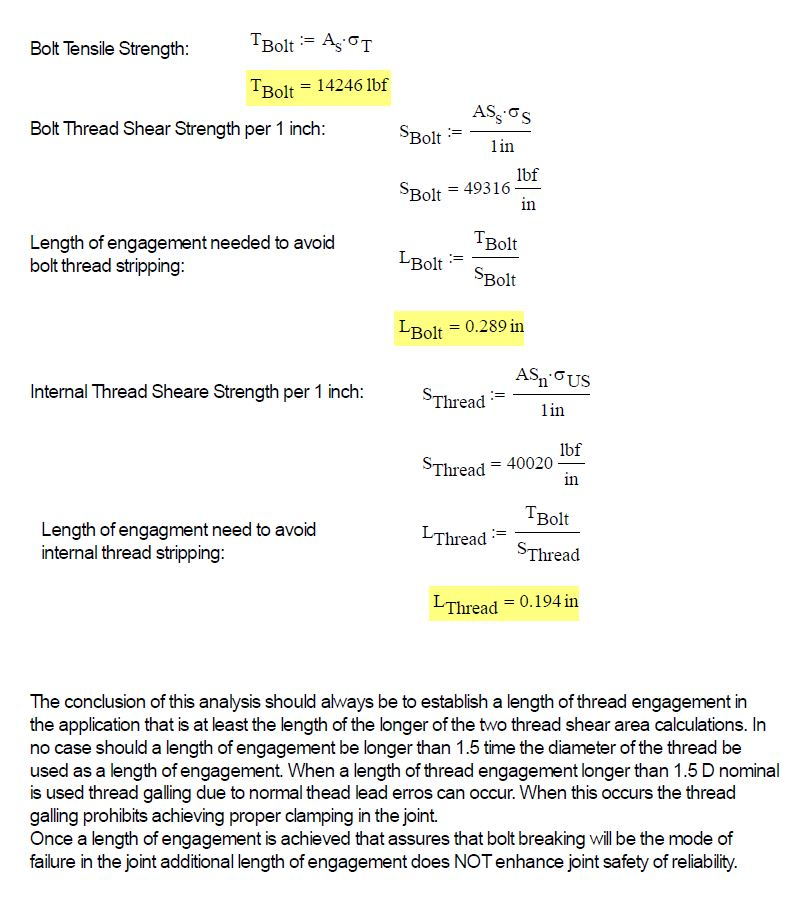
Test drive. Overall I'm happy with it (needs to be locked down). It looks as expected, some may like it, some may not. I may rock it on the street or just track. I don't know yet. But I did have some concerns with regards to the bolt strength in the back of my mind. This is a tow hook/strap after all and if you need to use it, you don't want it to fail.
So, I couldn't resist but to do some math/engineering. The equations, constants, material properties are all referenced. Bottom line is that the threaded connection is strong enough (rule of thumb 5-6 full threads of engagement always). I have at least .50in of thread engagement between a Grade 8.8 (SAE 5) 7/16-20 eyebolt into a Stainless Steel Type 304 threaded hole. Likely the weak point would be the threads in the aluminum bar, which the adapter is threaded into (this could also be calculated). I'll need to trust Porsche that they did their homework on the tow point. In general it doesn't take that much force to move a 3000lb object that can roll.
So what are the next steps.
1. Tighten and loctite the assembly together.
2. Update the solid model.
3. Update/create a new detail drawing.
As some members mentioned they are interested in this item. I could have it quoted by a local machine shop. No guarantees on clocking/orientation or you would need spacers/washers.
Finish this damn thing so we can throw some money at you! We need to at least get you back to breaking even on time and materials! Thank you for the effort!
Finish this damn thing so we can throw some money at you! We need to at least get you back to breaking even on time and materials! Thank you for the effort!
I will say, I think this tow strap would look sick on a Guards Red .2 RS
I will spend some time tonight, to finalize the drawing and get some quotes out to some machine shops.


 03-06-2021 | 01:39 AM