When you click on links to various merchants on this site and make a purchase, this can result in this site earning a commission. Affiliate programs and affiliations include, but are not limited to, the eBay Partner Network.
Don't know if this will help, but just in case. I'm attaching the diagram form the 981 below. Obviously, this won't match yours (comparing your table below, it doesn't), but I'd expect to see the same connections. If you look at any of the wiring diagrams, these "TERM XX" will be consistent (my assumption).
For 981:
TERM31 - Ground to the seat memory box
TERM30 - +12v, Hot at all times
TERM15 - +12v, Switched
Yours seem to be a little different. You have a TERM38 that I don't have. I definitely sent power to both of the +12V (hot at all times and switched). I recall also at one point errantly sending +12V to the LIN line, as it is pink like +12V in the diagram, and I didn't realize that LIN is a 1-wire data bus. LIN operates at 0-12V, so that was actually not a major oops as you'd think it would be. You might actually try sending 12V to the LIN line if you have one, as maybe it also needs to wake up.
I think you're doing the CAN Low to CAN Low, CAN High to CAN High right, per your description. I wonder if you need a 120Ohm termination resistor for some reason? I can't recall if I had the resistor or not. If you try this, there is no risk to your modules. I think you might also try measuring the resistance across the CAN High and Low. I think it should be 120 Ohms, but don't quote me on that. If you figure out what it should be, please post it up. Also put your meter across the CAN High and CAN Low and measure the voltage with the Gateway powered up. Try this without the seat hooked up. Your meter should go from 0V to 2.5V rapidly (IIRC). If you don't see anything, then you probably don't have the Gateway powered up correctly. They hook up the wires to the seat. You should still be able to see this rapid 0-2.5v. I had a little oscilloscope. Your meter may show you an average of 0 and 2.5v, say 1.7 volts depending on the duty cycle of the CAN bus message form. I think that would tell you that you have the Gateway working.
I used a 12V battery from my kids power wheels, and that was plenty of juice.
I also hooked directly to the seat wiring pigtail...I did not try to hook up directly to the seat control module, though I don't see why you can't do that. For sure the wire colors to the module should match the wiring diagram, or you don't have the right diagram. These also may be often different passenger vs. drivers. I agree that it is odd that the ground wire to the module is a red wire. I'd have expected brown, or brown with a white stripe. Just about anything but red. Don't fry your module. Also, did they not give you the seat wiring to the yellow main disconnect? I think that's the main thing you need.
My 981 seats have memory on both the Drivers and Passengers sides, so I had to do this twice. Neither worked beforehand (they didn't move at all). What I mean to say is that I didn't get lucky. Whatever I did, it is why the seats worked afterwards. Hopefully you can get it to work too!
I may have already said this in a previous post, but before I figured out how to wake up my existing 18-way controllers I bought a 14-way on eBay. When I plugged it in the seats moved in 14 ways. Note all 18 didn't work, just the 14. This confirmed for the that there was something locked in my seat control modules and encouraged me to keep trying. I suspect yours is the same. My seats were definitely in an accident. My seat belt latch pretensioners were both deployed. I think something about the accident locks the seat memory module. Maybe they don't want a pushed in door to hit a seat button and further crush you further after an accident. That would make sense. In any case, if this doesn't work out, you can likely buy a control module off eBay. They run $50-$100 for the 981 IIRC. It's the same module for that generation of Porsches (Cayene, Panamera, Cayman,etc) and it's likely the same deal for the XX7 generation too. The modules coded to 2, 4, 14, 18, whatever number of "ways". So again, if you get there, buy one with the right number of "ways".
Thanks for the information. I may have some time tonight to work on this. I understand we are working with slightly different components, but you have provided some avenues for further exploration.
I may need to explore the seat harness shown in post #24 and determine exactly what is going on with the thick red wire. I found a post showing the process for installing non-memory seats in a 997 or 987 that had memory seats installed at the factory. The post shows removing the red wire from the black connector and moving it to the large yellow connector. This seems to suggest that it is actually a +12-volt power source.
I should have time on Monday to check whether I am powering the Gateway module and determine whether there is voltage on the CAN lines. I want to look at your diagram on a larger computer monitor and take some time to thoroughly digest this information.
I revised the wiring in the 12-pin Audi connector that plugs into the Gateway. Here's the configuration:
A1 – Red/Blue – Power
A 11 – Brown – Ground
A5 – White/Gray - CAN Low – Black on Seat Memory Connector
A15 - Green/Gray – CAN High – Yellow on Seat Memory Connector
I applied power and ground to pin A1 and pin A11. When I measured the voltage on the CAN lines it was fluctuating in the 9- 10 volt range which is higher than the level you expected.
I hooked everything to the seat and none of the controls operated. I'll double check everything and see whether there are any other configurations that make sense.
I revised the wiring in the 12-pin Audi connector that plugs into the Gateway. Here's the configuration:
A1 � Red/Blue � Power
A 11 � Brown � Ground
A5 � White/Gray - CAN Low � Black on Seat Memory Connector
A15 - Green/Gray � CAN High � Yellow on Seat Memory Connector
I applied power and ground to pin A1 and pin A11. When I measured the voltage on the CAN lines it was fluctuating in the 9- 10 volt range which is higher than the level you expected.
I hooked everything to the seat and none of the controls operated. I'll double check everything and see whether there are any other configurations that make sense.
Hi keeping my eye on this currently trying to achieve the same thing?
Obvs you can purchase a switch and a harness and convert the memory seat to a non but that's like �750...
Thanks for your interest. If you have any suggestions, please let me know, Floridaman has been helpful, but he installed 981 seats in his 996 and I can't seem to replicate his process with my 997 seats.
I originally bypassed the memory function on my Mercedes which, as you suggest, could be an option with the Porsche. However, another forum member (Saabatour who also posted on this thread) found a way to use the memory function. I adopted his method and activated the memory function. You can read about the memory installation here.
I have not made a formal accounting, but it appears that the Mercedes and Porsche seats have similar components, and I wouldn't be surprised to learn that they were manufactured by the same suppliers. One difference is that Mercedes vehicles are much more plentiful, and I was able to find many of the parts for the Mercedes at the local pick and pull or other recylers at low prices. As you point out, the manual switch for the Porsche is expensive. I'm reluctant to pay for expensive components that I might not need.
I've been busy with work and other obligations, and I have had other obligations. I'll keep working on this as time permits. I'll post any information I find on this thread. Please do the same.
Last edited by KevinH2000; 03-11-2023 at 02:06 PM.
A14 - TERM 15
Sheet 7 is CU Gateway. That shows TERM 15. --> Sheet 6, Cell D15
Sheet 6 is CU PAS. TERM 15 is "START CONSUMERS"
That TERM15 wire is black/black.
I don't have a lot of experience with Porsche data lines. But I would think that this may be a data line, LIN or something maybe. I did a little google search, and it may just be switched power from the PAS module? Maybe only positive if the immobilizer is all happy. You might want to probe this on your car and see what it is. If it's +12V when the key is in the ignition, then I think you'll want to send 12V to this pin on the gateway module. This may be the equivalent of the more cleanly labeled Switched 12V on the 981 diagram (also TERM15!).
A13 - Wake Up Cluster / PCM
I would think that this is a line that goes out from the gateway to the other modules. I may be wrong about that though.
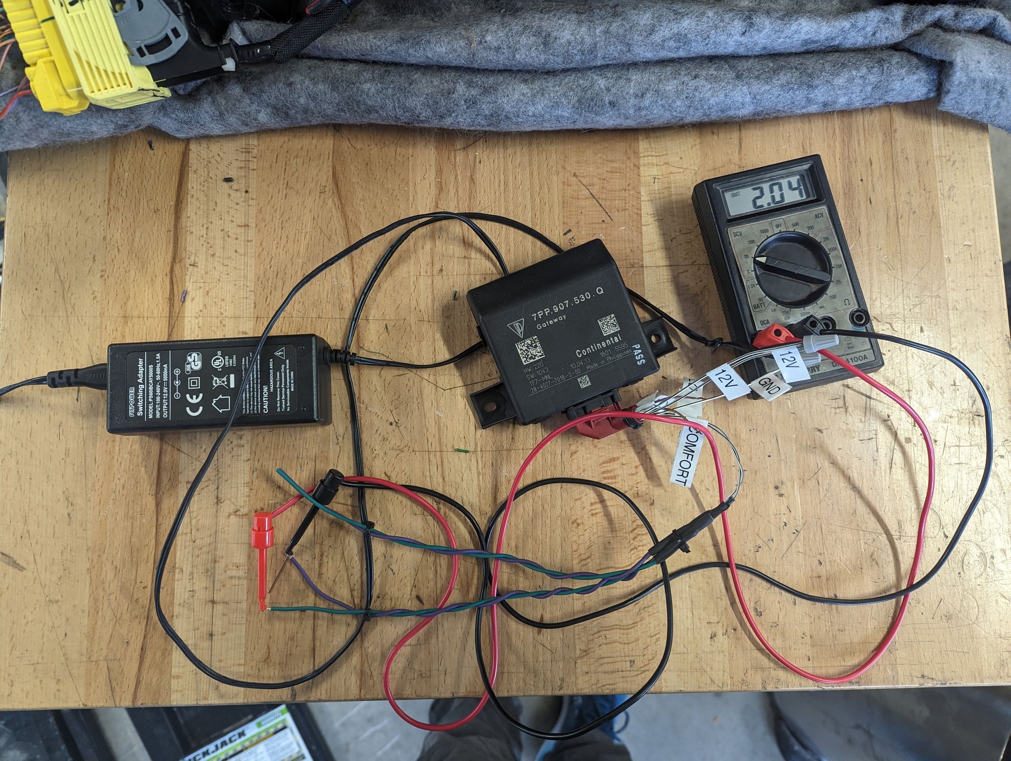
That is very curious that you were measuring 9-10V across the CAN bus lines on the gateway module. I went and checked a CAN bus system that I had easy access to (Megasquirt MS3 system) and that showed a solid, not fluctuating interestingly, 2.0V. This is with my meter's positive to Can High, and negative to Can Low. I then pulled out my gateway module, and hooked up ground to the one pin, and then 12V to the constant and switched power inputs. Again, I get a non-fluctuating 2.0xV. Now if I only have one of the two 12V connections, I get nothing, zero volts. For the fun of it, I hooked up my little DSO nano oscilloscope to the can lines, and I can clearly see a signal being sent out.
I don't know how you're getting 9-10 volts, unless you're measuring 12V to one of the CAN lines. You want to measure across the CAN Hi to Can low, and that is the polarity. I tried this.
With both 12V lines hooked up (Gateway is working):
I get 2.0V across the CAN High to Can Low.
I get 10.77V across 12V to Can Low
I get ~9V across 12V to Can High
It looks to me like you were measuring from 12V to the can lines? Or do you have 12V tied to one of the can lines for some reason?
I think you want to make sure that the Gateway is sending out valid can messages before moving on.
Note that the little 12V power supply was just for messing with the Gateway here. When I hooked that to the seat, I had used a larger 12V battery to power the seat as well. Interesting note and something that I came across just yesterday - with CAN I don't think you need any sort of a common ground for the signal. It just reads the voltage difference between the high and low wires. I think I could have used this little 12V source for the Gateway, and a powered the seat from a battery and not tied the grounds together, and it likely would have worked the same.
Just to confirm, I have a set of multi way heated seats from a 997.1 and I'm trying to install in a 2005 CS with non heated 2 way seats, so I've got wiring up of the heating added into the mix.
Thanks for the replies. I did not have much time to work on this this weekend. I will read through your input and continue to experiment with different concepts. In the few minutes I had to devote to this, I built a simple test rig for CAN connections. I hope this will help me obtain more accurate voltage readings. I also have not ruled out the possibility that I have a defective memory module (as Floridaman suggested) or another damaged component.
I have not. I will post updates when I start work again. Based on my work schedule and other plans, I may not be able to devote much time to this until October.
If you are working on a similar project, please send me a PM and we can discuss collaboration.
I have not. I will post updates when I start work again. Based on my work schedule and other plans, I may not be able to devote much time to this until October.
If you are working on a similar project, please send me a PM and we can discuss collaboration.
I would love to, though it won't let me PM you - probably because I'm a new user.
I won't be able to physically work on this project for a while due to some work considerations. While I am on hiatus, I am learning about CAN bus with the goal of determining whether I am making a fundamental error in the way I am constructing my wiring harness.
One of the key points in the video is that a CAN bus needs to have a 120-ohm termination resistor at each end of the CAN bus. Some devices apparently incorporate the resistors into the devices on each of the CAN nodes, but I lack the expertise to determine whether the devices I'm using are designed this way. I've ordered some 120-ohm resistors (they are not expensive) and plan to add them to my set up. I will post an update in September or October when I have had an opportunity to work on this project.
As always, I will appreciate any suggestions or comments.


 03-05-2023 | 02:36 PM