When you click on links to various merchants on this site and make a purchase, this can result in this site earning a commission. Affiliate programs and affiliations include, but are not limited to, the eBay Partner Network.
I have put 15,000 miles on my LT1 motor (C7 Grandsport) and it's a torque monster. Really appreciate it's simplicity in engineering especially in today's world and i'm amazed how much power they are capable of - in fact sending mine up to Ligenfelter for their 600hp package. The build sheet blows my mind and for only 9k...and some Corvette people say that is overpriced - nope that's a bargain to me.
A couple of years ago GM set a smoking hot lap at the Ring with the new LT Camero. The driver was a Rennlister that was a GM engineer, not a professional driver. He was very, very good however!
By the way, what you are doing is scrareligious, but you sure are doing it well! I can tell you are a first class machines with no fear of digging in. Rebuilding that 3.8 yourself might have been easier and cheaper than you imagine given your skill set.
He was over in the 991 forum, GT3 iirc. I don't think he worked fro GM I think he was hired. it Was either the Z-28 vs Turbo 991 or ZR1 vs Turbo, on the ring. I've spent some time touring with someone who was there with him. Hot shoe for sure!!
I'm not sure who exactly that is, but we work pretty closely with that team. We had one member from our group accompany one of the ring trips. The Camaro team is great to work with, the 6th gen is an amazing car if you ever get a chance to drive one. Nothing beats it on coat for performance.
I just so happen to have a 997 starter for sale if you need one...
Mark was there on that trip. He drove the ring another time but he didn't set the record that was set at the time.
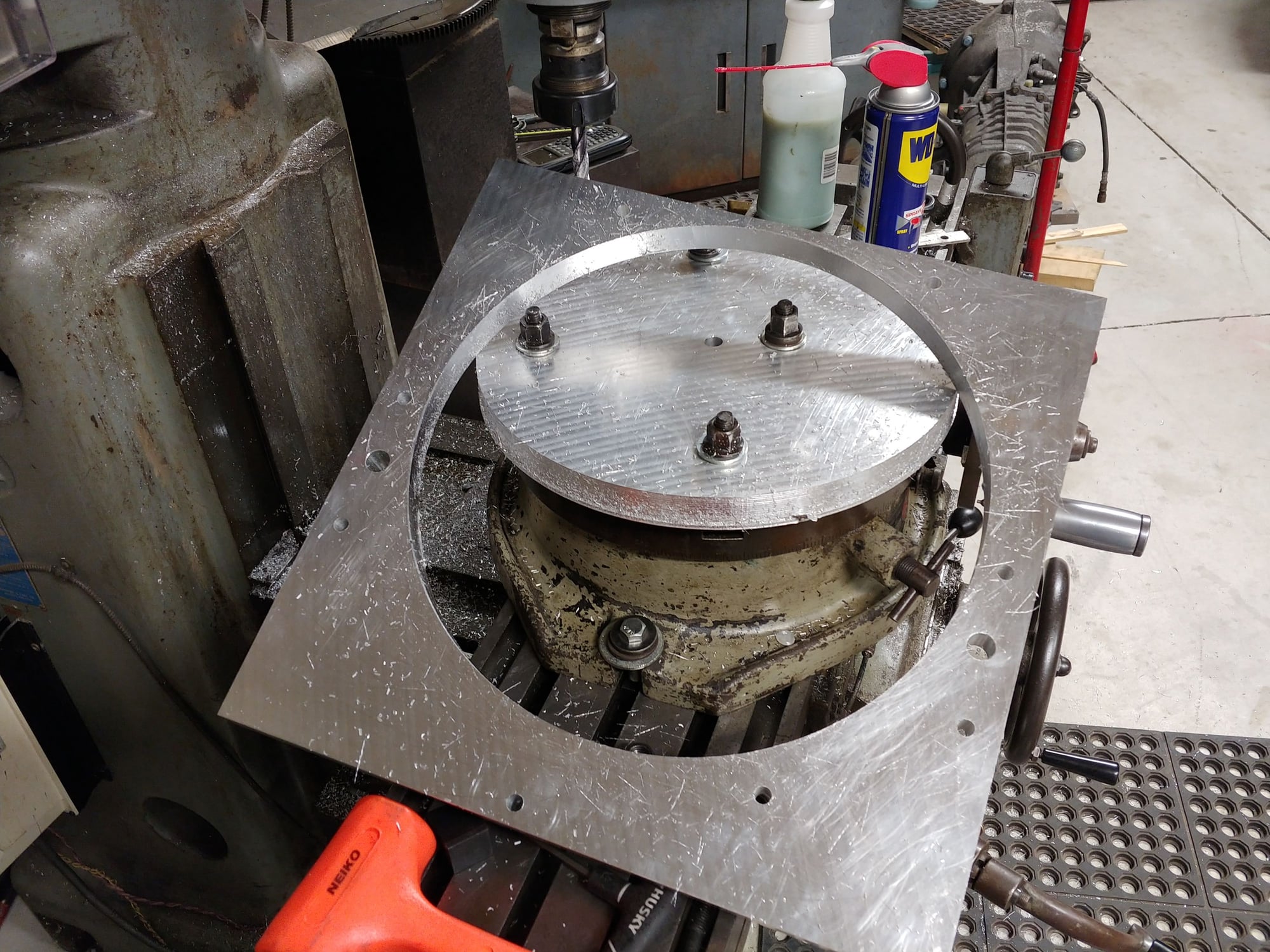
Couple fresh pictures. Used the new to me rotary table this weekend to clearance the 1" piece of aluminum and finish it up. I'm using the pair of locating pins on either side of the LT1 block to keep the two plates concentric. I added a couple flush mounted M6 screws to hold them together, but it's just for ease of assembly. The LT1 bellhousing bolts all go through the pair of plates for now.
Troyke 12" rotary table. The thing is a tank, 135lbs of made in 'Merica cast iron. The left over of the bellhousing will make a perfect fixture plate for the future too. Couple of the Porsche G96 threaded points I decided to use some 1144 I had to make threaded inserts. Bake the aluminum in the oven at 450 for 1 hour, and the insert drops right in! Afterwards, it won't budge. Aluminum does not like press fits, it's much better to use heat for interference fits. Just have to be careful to not get it too hot so as to ruin the strength properties.
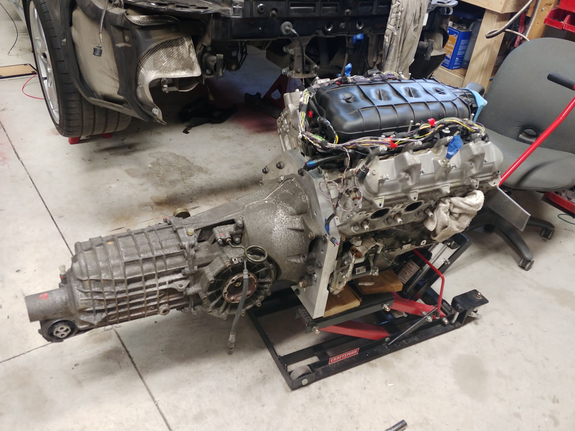
Matched up and balanced on the motorcycle jack, ready to go in and find it's final mounting points.
Just stumbled on your thread and read it through. I initially thought you were doing a Chavis Performance Engineering LS swap on your own, but clearly not. Loving the details! The only downer is that the swap isn't complete - will have to follow along in 'real time', like back in the day before you could binge-watch a show on a streaming service. It's like we're back to cable now and have to wait every week for a new episode, lol.
Couple updates in the next post. Starting with a question. As a part of my tip to manual swap, I had to run new clutch lines. I ordered a complete set from DC automotive. Fairly easy to install for the most part. So far the hardest part of the tip to manual swap was the installation of the clutch pedal! But I'm not done yet..
Anyway, there is one line that runs from the brake reservoir to the clutch master cylinder. I thought I had it in the correct location. I have it passed through a grommet right next to the AC drier. But it seems to be too long to properly connect to the port on the brake reservoir. *Just a note, this is still the Tip brake reservoir, I need to swap it for a manual one. The port is blocked on the tip.
Added some yellow highlight on the pathway I have the line routed.
While I had the fender well out doing the clutch lines, I decided to test my washer pumps. Both headlights and windshield were not working. Windshield sprayer was getting 12V to the pump, assuming the pump is dead. Ordered a new one. Headlight sprayer was not getting 12V, and the fuse is good. Not too worried, just like having everything working. I've heard it's possible to disable the headlight washers if you have the sport chronos package?? I couldn't find any info on this though.
Other than that, I finished pairing up the engine and transmission, mounted them and played with hood clearance. The hood shuts with the spoiler motor installed even. However, I only have about 3" between the latch and the throttle opening, which needs a 4" inlet. I'm thinking I will make an elbow to mount between the throttle body and intake. I ordered the tightest 4" elbow I could, so maybe it will work, I will try next time I have the engine back up in the car.
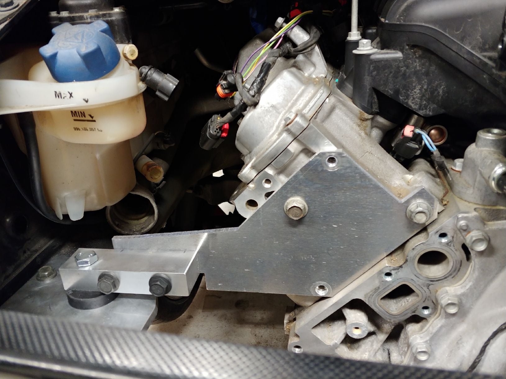
Nearly finished mounts. The driverside sheet metal mount had to be removed, I welded in 3 sleeves tapped for M10. Welded on both top and bottom of the frame rail to ensure they are more than adequate. The plate mounted to the head is only 1/4". Originally I planned to use 3/8 after these were mocked up. Now I'm wondering if it's even necessary. Paired up. I have this car on almost the lowest tooth of my 6 ton jack stands, the engine is a breeze to install like this, all of 10 minutes. Finding more uses for the rotary table. This 7075 aluminum piece is what my flywheel adapter will bolt to. It is pinned to the flywheel followed by 6 grade 12.9 M10 bolts at a 3.7" diameter (not shown in this picture). That hunk of 4140 will be turned into the adapter that the 991.2 flywheel bolts to. Probably not too clear at this point. Maybe within a week I'll have more pictures if it works out as I planned.
Yes, I've been thinking the same, which is is my thought on remaking the plates that bolt to the head in 3/8. But at the same time, fore/aft movement should be totally handled by the transmission forward mount. Same as the 997 engine, the engine mounts are only designed to hold the weight of the engine, and have very little resistance to moving forward I think. Either way, I'm thinking I will remake them in 3/8... I have the plate, it won't take long to trace the pattern and cut it out. Doesn't hurt to be overkill in these scenarios.
Pls excuse the horrible stick figure outlines
The stock engine carrier and mounts resist up/down, left/right, forward/rearward and rotational forces. If you rely on the trans mount to provide most of the resistance forward and rearward then it's the rotational forces that I concern me the most.
I'm long removed from my engineering classes but this is what I'm thinking.
The green areas are built up well to resist compression and separation in a rotational force.
Think of the red arrow pointing to the area on the plate (behind the block) underneath the inner bolt hole. A crack could from under the bolt hole and weaken that piece where it has the least amt of material.
I understand what point you are talking about. Yeah, that is probably the thinnest part, probably best to just go for the 3/8. Luckily, bolted assemblies like this, you are really relying on the clamp force/friction of the plate and block in this assembly, so it should be good.
I really appreciate what you are able to make in your shop, especially with the aluminum stock. I have to leave my garage to get time on my friends plasma cutter and I've only been working with steel. Safer as a newbie.
Aluminum is definitely tough when it comes to anything heat related like plasma. Someday I'll learn to weld it... For now, I just stick to the bolted assemblies.

 05-24-2020, 09:00 AM