
997.2 Ignition Switched Footwell Accessory Socket
 04-17-2019, 06:53 AM
#1
Intermediate
Thread Starter
The cigar lighter and footwell accessory sockets in the Gen 2 are always live (I think this is also the case with Gen 1). This is great when using a battery conditioner (e.g. CTEK) as it means this can be connected via the cigar lighter. NB - The cigar socket is protected by 15A fuse whereas accessory sockets by 7.5A - You must always use the cigar socket for big loads (e.g. tyre compressor) and for charging.
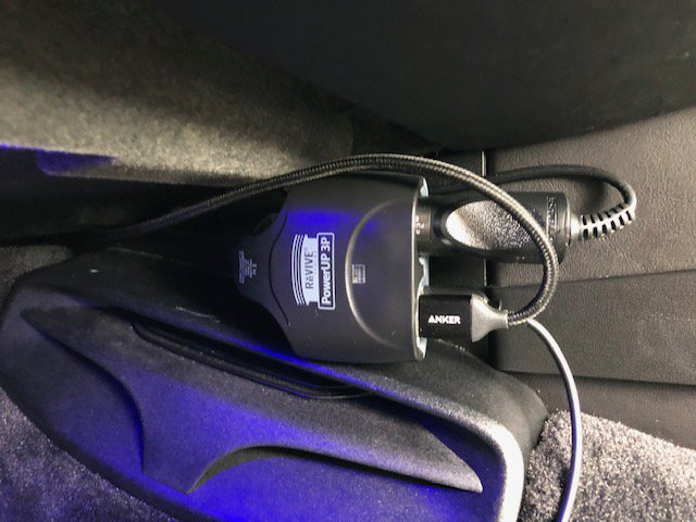
However, I am not sure how many others have the issue of having several accessories plugged into the accessory socket - in my case, a charging adaptor for phone; a Road Angel and a dash cam. Whilst all are in standby when not in use, I do not unplug them as it's a bind to unplug/plug in the blessed multi-way socket I use for all these adaptors; it also means the wiring, normally neatly concealed has a habit of coming out of its hiding places. What I do find is that the combined drain of these various devices, albeit in standby, contributes to the draining of the battery when left for any period of time.
In an ideal world, the accessory socket(s) would be switched (ie turned on with ignition) and off when the ignition is off. Further, it would be helpful if the socket could then be turned on permanently should the need arise.
I considered a couple of options. One could run a switched live from the fuse box situated in the drivers footwell (from fuse row C) and use a SPDT switch to select between this and permanent 12V supply, wiring this to the accessory outlet. In the end I elected to use a relay to switch the existing 12V supply and avoid changing the loading on any of the existing fused circuits,
The relay is activated from a tap taken from an existing switched (Terminal 15) wire from behind the dash - I used the supply to the switch module for PASM, spoiler etc. as this is fairly straightforward to access. Given this is only used to activate the relay, the additional load is no more than around 120mA (relay coil impedance about 100 ohms).
This is the circuit diagram. PLEASE NOTE that you should check any components you use as they may differ. I used a micro relay with a built in flyback protection diode - if you use a similar relay, these must be connected the correct way round. I also used an illuminated switch so again, ensure the pins are connected correctly for the LED to illuminate when switch is on.
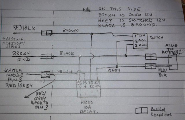
Relay:
Pin 30 - Permanent 12V
Pin 87 - Switched 12V Output
Pin 86 - Coil+
Pin 85 - Coil-
Switch
Pin 1 - 12V
Pin 2 - Accessory
Pin 3 - LED Ground
These are the installation steps I followed.
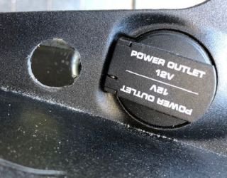
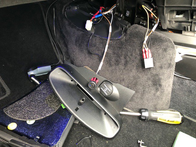
1. Remove the accessory socket panel from passenger footwell. My car is a convertible so its a bit different to coupe. On the convertible the screw is hidden behind the vaned plasix insert which you have to unclip first. Undo the screw and you can then unplug the accessory socket from the cable harness.
2. I drilled and filed out a 20mm hole ready to accept a toggle switch.
3. To get access to the cable harness for the PASM, Spolier, Sport Mode switch module, you have to remove the passenger and driver side trim panels. On the passenger side, remove 2 torx 20 screws. On the drivers side there is a little carpeted piece which is unscrewed first (the torx 25 screw is hidden in the carpet trim so poke around with finger to find it. Once this piece is removed, the trim can be undone (2 torx 20 screws). The side panel trims can now be removed by pulling/pushing forward. These side panel trims are a fiddle to remove as the front edges are retained by clips. Be gentle and patient when removing these.
4. Once removed the trims you have access to the clips that retain the switch module.
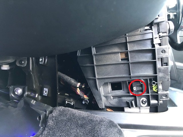
5. Depress these clips and the module can be withdrawn. There is also a little clip on the top of the switch module which has to be pushed down a bit to fully remove the module. You now have access to the plug to the switch module and can unplug it.
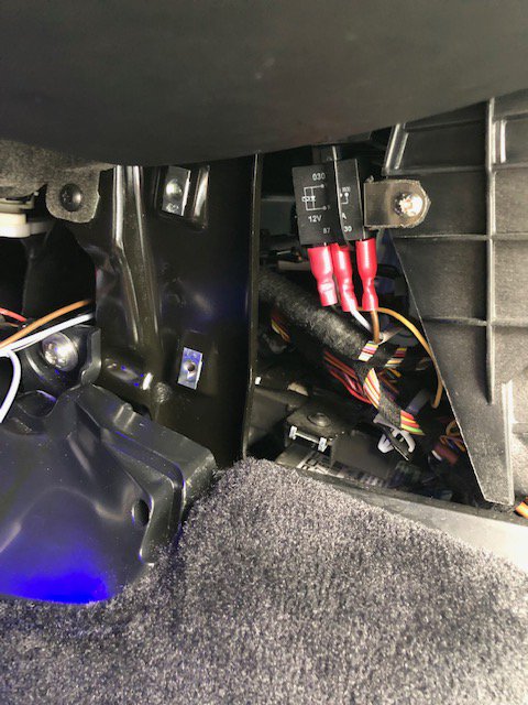
6. I next turned my attention to the relay. I fashioned a little bracket from a bit of bendy metal strip I had laying around. The relay is secured using a cable tie. I also put a bit of rubber strip on the bracket just to avoid squeeks etc.
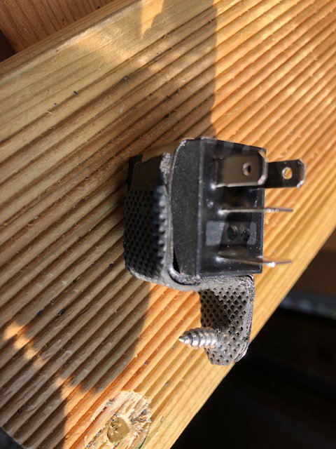
7. My chosen position for the relay. I drilled a small hole in the plastic cage and secured using a self tapping screw. Note the cable tie securing the relay to the bracket. There are other options for installing the relay. Make sure your chosen location does not get in the way of the side panel or other bits.
7.
8. The next step is where we start to do more invasive surgery.
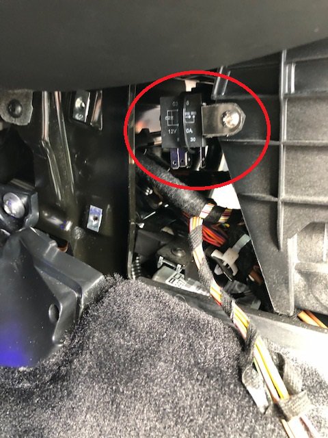
As a precaution I removed the fuses to the circuits I was doing surgery on. Fuse 8 on row A feeds the accessory socket and Fuse 8 on Row C feeds the button module.
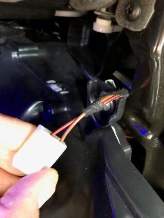
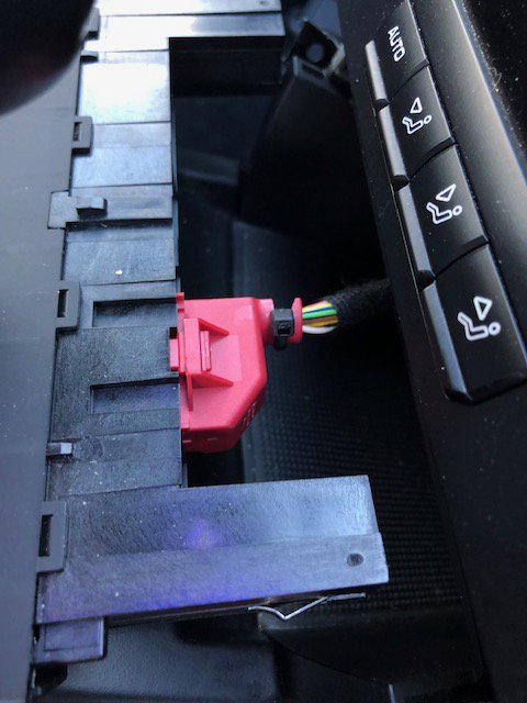
The switched (Term 15) supply I am using is on pin 3 of the button module and is supplied via Red/Grey wire. Be really careful here as there are also Grey/Red wires. You need the RED/GREY on PIN 3. I removed the red case bit of the plug (cut the little cable tie) in order to make life a bit easier. I cut the RED/GREY and tapped the wire (using a bullet connector) adding a tap wire (yellow in pictures). I then put the plug back in the casing and re secured using a new cable tie. I looped the yellow wire through the cable tie to give a bit of strain relief to the bullet connector.
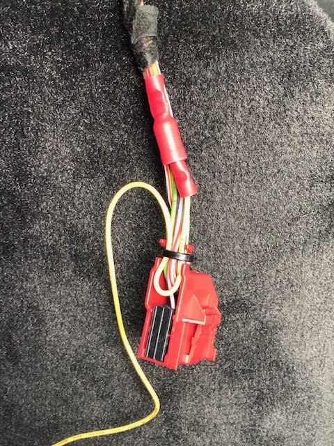
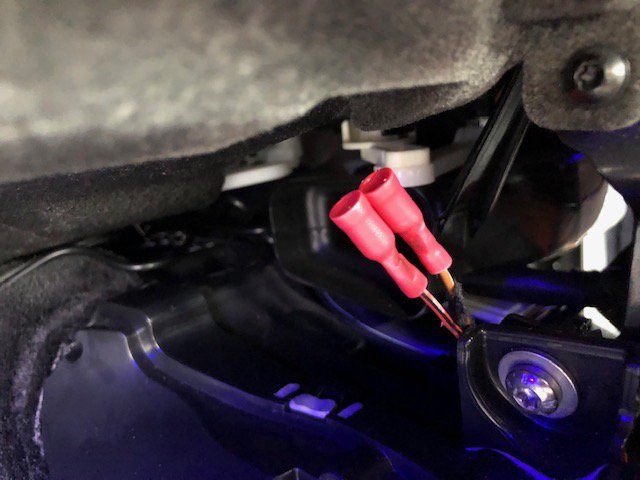
9. Next I cut off the plug to the accessory socket and attached female bullet connectors to the ends. Be careful here as the loom cable is not very long and you will need to get access to the cut ends to crimp on the female bullets. The RED/BLACK cable is permanent live.
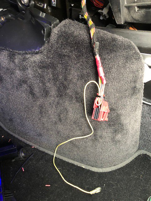
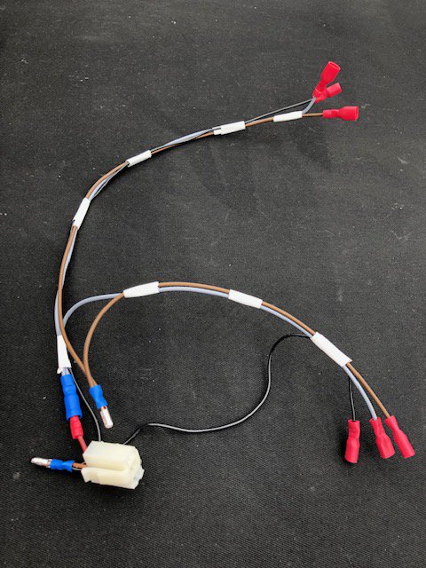
10. I now fashioned a wiring loom to connect everything up and installed this in place. I removed the relay to make connecting it up easier (which is why relay is dangling in footwell in one of the pictures).
11. Now it is a case of putting everything back together.
Put the side panel trims back in first. Again, can be a bit of a fiddle to get them lined up, but do not force anything, when they are lined up right they will slide in and clip in place. Secure them using the torx screws.
Put in the little carpeted piece on drivers side.
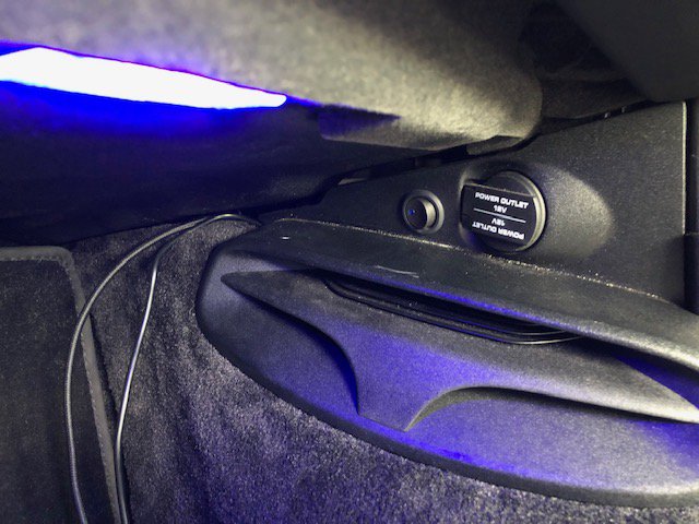
Put back the accessory socket panel. Be careful regarding placement of cables. On Cabrio, be careful not to end up with cables going into the air duct; move them to the right where the accessory socket and its plug go. Do not be rough, everything should go into place without force. Dont forget to clip in the vaned insert (Cabrio).
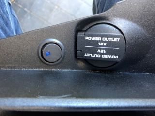
12. Job Done. When toggle switch is in the Off position, the accessories are powered when ignition is on. Can override this by flipping switch to on position.
However, I am not sure how many others have the issue of having several accessories plugged into the accessory socket - in my case, a charging adaptor for phone; a Road Angel and a dash cam. Whilst all are in standby when not in use, I do not unplug them as it's a bind to unplug/plug in the blessed multi-way socket I use for all these adaptors; it also means the wiring, normally neatly concealed has a habit of coming out of its hiding places. What I do find is that the combined drain of these various devices, albeit in standby, contributes to the draining of the battery when left for any period of time.
In an ideal world, the accessory socket(s) would be switched (ie turned on with ignition) and off when the ignition is off. Further, it would be helpful if the socket could then be turned on permanently should the need arise.
I considered a couple of options. One could run a switched live from the fuse box situated in the drivers footwell (from fuse row C) and use a SPDT switch to select between this and permanent 12V supply, wiring this to the accessory outlet. In the end I elected to use a relay to switch the existing 12V supply and avoid changing the loading on any of the existing fused circuits,
The relay is activated from a tap taken from an existing switched (Terminal 15) wire from behind the dash - I used the supply to the switch module for PASM, spoiler etc. as this is fairly straightforward to access. Given this is only used to activate the relay, the additional load is no more than around 120mA (relay coil impedance about 100 ohms).
This is the circuit diagram. PLEASE NOTE that you should check any components you use as they may differ. I used a micro relay with a built in flyback protection diode - if you use a similar relay, these must be connected the correct way round. I also used an illuminated switch so again, ensure the pins are connected correctly for the LED to illuminate when switch is on.
Relay:
Pin 30 - Permanent 12V
Pin 87 - Switched 12V Output
Pin 86 - Coil+
Pin 85 - Coil-
Switch
Pin 1 - 12V
Pin 2 - Accessory
Pin 3 - LED Ground
These are the installation steps I followed.
1. Remove the accessory socket panel from passenger footwell. My car is a convertible so its a bit different to coupe. On the convertible the screw is hidden behind the vaned plasix insert which you have to unclip first. Undo the screw and you can then unplug the accessory socket from the cable harness.
2. I drilled and filed out a 20mm hole ready to accept a toggle switch.
3. To get access to the cable harness for the PASM, Spolier, Sport Mode switch module, you have to remove the passenger and driver side trim panels. On the passenger side, remove 2 torx 20 screws. On the drivers side there is a little carpeted piece which is unscrewed first (the torx 25 screw is hidden in the carpet trim so poke around with finger to find it. Once this piece is removed, the trim can be undone (2 torx 20 screws). The side panel trims can now be removed by pulling/pushing forward. These side panel trims are a fiddle to remove as the front edges are retained by clips. Be gentle and patient when removing these.
4. Once removed the trims you have access to the clips that retain the switch module.
5. Depress these clips and the module can be withdrawn. There is also a little clip on the top of the switch module which has to be pushed down a bit to fully remove the module. You now have access to the plug to the switch module and can unplug it.
6. I next turned my attention to the relay. I fashioned a little bracket from a bit of bendy metal strip I had laying around. The relay is secured using a cable tie. I also put a bit of rubber strip on the bracket just to avoid squeeks etc.
7. My chosen position for the relay. I drilled a small hole in the plastic cage and secured using a self tapping screw. Note the cable tie securing the relay to the bracket. There are other options for installing the relay. Make sure your chosen location does not get in the way of the side panel or other bits.
7.
8. The next step is where we start to do more invasive surgery.
As a precaution I removed the fuses to the circuits I was doing surgery on. Fuse 8 on row A feeds the accessory socket and Fuse 8 on Row C feeds the button module.
The switched (Term 15) supply I am using is on pin 3 of the button module and is supplied via Red/Grey wire. Be really careful here as there are also Grey/Red wires. You need the RED/GREY on PIN 3. I removed the red case bit of the plug (cut the little cable tie) in order to make life a bit easier. I cut the RED/GREY and tapped the wire (using a bullet connector) adding a tap wire (yellow in pictures). I then put the plug back in the casing and re secured using a new cable tie. I looped the yellow wire through the cable tie to give a bit of strain relief to the bullet connector.
9. Next I cut off the plug to the accessory socket and attached female bullet connectors to the ends. Be careful here as the loom cable is not very long and you will need to get access to the cut ends to crimp on the female bullets. The RED/BLACK cable is permanent live.
10. I now fashioned a wiring loom to connect everything up and installed this in place. I removed the relay to make connecting it up easier (which is why relay is dangling in footwell in one of the pictures).
11. Now it is a case of putting everything back together.
Put the side panel trims back in first. Again, can be a bit of a fiddle to get them lined up, but do not force anything, when they are lined up right they will slide in and clip in place. Secure them using the torx screws.
Put in the little carpeted piece on drivers side.
Put back the accessory socket panel. Be careful regarding placement of cables. On Cabrio, be careful not to end up with cables going into the air duct; move them to the right where the accessory socket and its plug go. Do not be rough, everything should go into place without force. Dont forget to clip in the vaned insert (Cabrio).
12. Job Done. When toggle switch is in the Off position, the accessories are powered when ignition is on. Can override this by flipping switch to on position.

The following users liked this post:
cbracerx (06-09-2021)
