When you click on links to various merchants on this site and make a purchase, this can result in this site earning a commission. Affiliate programs and affiliations include, but are not limited to, the eBay Partner Network.
Disclaimer: This how to is not a plug and play solution. I do not have a glove box in my 996, so I decided to add a bluetooth chip to the headunit and have everything self contained within the housing. I wanted avoid having an external unit that I would other wise need to mount somewhere.
Power source (Can be 12V wall plug or 12V from vehicle)
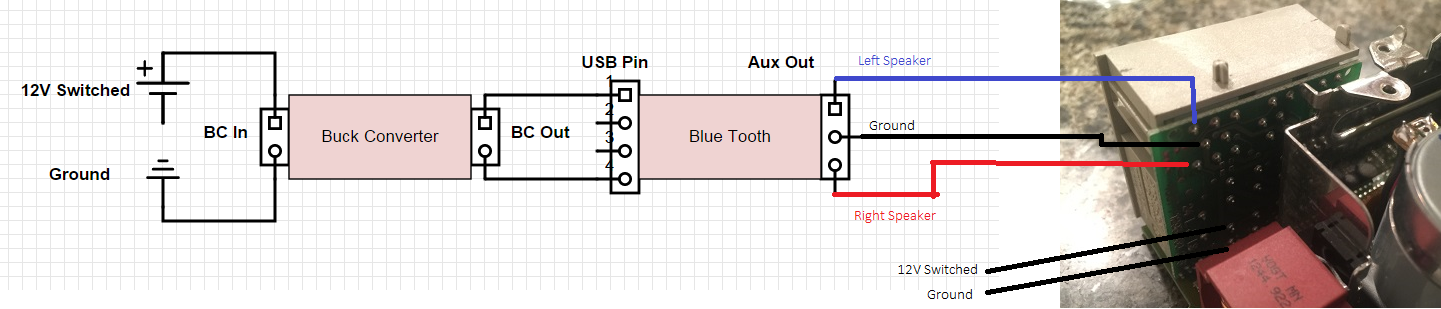
Premise: The idea here is to utilize the 12V switched power supply and ground supplied to the head unit. However, USB powered devices run on 5V, and if we plug the 12V strait to our bluetooth, bad things happen. This is what a buck converter is used for, dropping that supplied 12V down to 5V, without generating a negligible amount of heat. (There are other ways to do this, but not as efficiently as a buck converter i.e. voltage regulator) Once we supply our 5V to the bluetooth unit, assuming you purchased one with an aux out, all you need to do is solder three wires from the aux out to the aux in on the becker. So let's recap, 12v from the car goes to the buck converter, the bucker converter powers our bluetooth unit, and the bluetooth unit sends an audio signal to the aux in of the head unit.
The schematic shows which pins we will be soldering our little circuit to. Notice, the 12V switched and ground pins are not that easy to get to, but it's very possible to make a solid connection with a little patience.
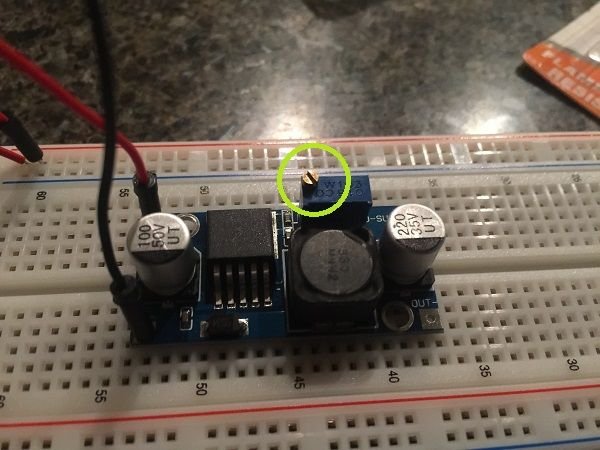
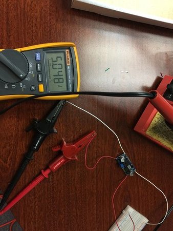
Before we go soldering our buck converter to this pin board, we need to calibrate it. Buck converters can be adjusted to output a certain voltage, I believe mines has a 40V max output. In order to calibrate it, we'll need to supply it with power, and measure the output voltage. I took a 12V power supply that plugs into the wall, chopped off the end and used a power strip to turn it on and off.
Here, you can see the adjustment screw that you will need to adjust.
Using your voltmeter, make sure you adjust the scew until you get a reading of 5V.
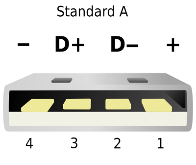
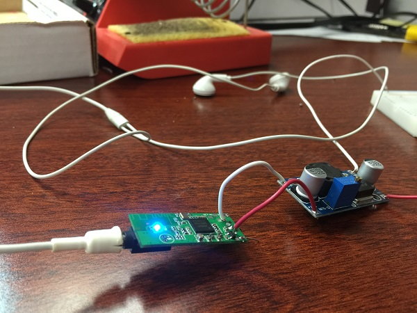
Once your buck converter has been set to 5V, you can go ahead and solder your output power and voltage to the input of the bluetooth. There are two main reasons we want a USB powered bluetooth unit. Firstly, the usb only supplies power, no data, so we do not need to worry about the middle two pins, only pin 1 and 4. Secondly, getting the "bluetooth signal" to an aux out has already been done for us. The only thing we need to do is desolder the male USB from the board. Make sure you take note of the location of pin 1 and four on your unit. Disregard pins 2 & 3.
Once you've desoldered the USB port, you can go ahead and solder your 5v lead from the buck converter to pin 1 and the negative to pin 4. Plug in a headset and make sure everything is in working order. Blue light is on and sound quality is good, so at this point you're ready to solder the circuit into the becker unit.
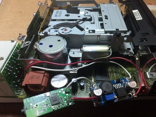
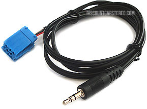
Dis-assembly and removal of the head unit is pretty strait forward. Locate the 12V source and ground mentioned in the schematic above and solder in your power source and ground. For the AUX out, you can do two things. Solder wires strait from the pins on the board to the head unit board, or use an aux cord and strip the end of the wire and solder that to the board. I recommend soldering jumpers strait from the board, but either way works.
I soldered the ground lead first, since that is the hardest to reach, followed by the 12V source. At this point, shrink wrap the buck converter and the bluetooth unit, then proceed to solder the AUX leads.
After shrink wrapping, I secured my circuit to the casset tape stand offs. You do not want your wires or leads to vibrate and wiggle around, as it could weaken the solder joint and eventually break off.
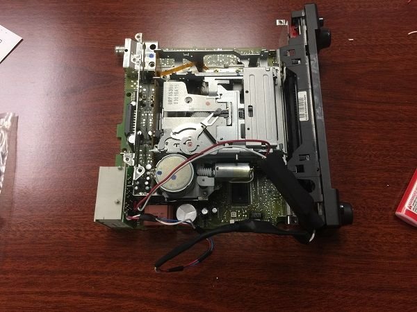
Before you place your becker back into the vehicle, do not plug in the wires that to go to the CD reader. Just keep them tucked in the back. All that's left to do before you can stream music via bluetooth is to just turn on AUX mode. I'm assuming you already know how to do that.
Final remarks:
I had originally purchased plastic screws, nuts, and washers to fasten the circuit down. I decided against this as it would make assembly and disassemble of the head unit a pain in the *** and drilling the circuit board was not an option.
I will be opening my head unit back up to put a ferrite ring around the aux lines, as there is a very faint hint of alternator whine when I have the volume cranked up.
Last edited by sweet victory; 01-19-2016 at 11:44 AM.
Question for the electronics gurus... If I want to keep the frunk-mounted CD changer, is there another option for getting the bluetooth signal into the head unit? Maybe a way of switching from Bluetooth to CD?
Question for the electronics gurus... If I want to keep the frunk-mounted CD changer, is there another option for getting the bluetooth signal into the head unit? Maybe a way of switching from Bluetooth to CD?
Yes. You can tap into the left and right signal and ground wires on the CD changer connection. Don't cut the ires just connect them to your bluetooth device as well.
Can't beleive people still use the CD changer! I've kept mines in there for the "oem-ness" since it would take a minute to have it up and running again.
Was contemplating on removing the casset player in the cdr220, since a hard drive would fit their perfectly. Hrmm...
Could you tell me how you located the speaker inputs for the head unit circuit board?
I have the fiber optic cdr 23 head unit and would like to add in this feature.
I looked up an installation manual for Becker's aux cord . Then to double check I was on the correct pin location, I used the continuity tool on my multimeter to ensure the node I was soldering to corresponded with where the becker aux speaker input would've gone.
 08-27-2015, 05:56 PM