
Crankshaft Position Sensor Diagnosis
 06-22-2014, 02:05 AM
#1
Instructor
Thread Starter
I posted in a separate thread most of the symptoms that I still have (see https://rennlist.com/forums/996-foru...placement.html).
It appears that I had two separate issues. First was a bad alternator, and that appears to be addressed (after two alternators).
But the remaining symptoms are still there: very jerky after the engine gets fully up to operating temp. It feels like the rev limiter kicks in but at rapidly lower RPMs. It first starts after 15-20 minutes of stop-and-go driving and I turn on the AC and rear window defroster to make it happen sooner. The RPM is at around 3k when it first starts. But within 2-3 minutes more it kicks in just starting from a stop, like 1k RPM and shudders throughout the range. Another couple of minutes and it's completely undrivable.
No problem at all when cold.
Durametric shows that the DME consistently throws P0336, "ref mark sensor", the crankshaft position sensor (CPS), when this happens. When it gets really bad it also throws various cylinder misfires (from both banks) and sometimes even the ABS/PSM warning lights go on. It's a whole engine phenomenon, not one bank or one cylinder.
So the logical culprit would appear to be the CPS. There are numerous reports on this forum and others about heat sensitivity of a failing CPS.
I spent the day today researching and measuring my CPS. I am not sure how to interpret the results and wonder if anybody here has gone through this, especially looking at the waveforms.
First, the wiring diagram shows 3 pins:
1. The signal
2. Ground
3. Shield (protect against electromagnetic interference)
At room temp the resistance between 1 and 2 should be between 800 and 1000 ohms according to Porsche diagnostic manual, and I measured 935. So that's OK. I also measured resistance between the harness pins and they were either 45k or 7k; no dead shorts and no opens, there are no specs here but I guess those are not obviously bad.
I heated up the CPS in a toaster oven (protected by foil) to around 190 F and it measured about 1.2k; a little higher as you'd expect but not an open circuit or short or something.
Then I measured the expected distance from the tip of the sensor when mounted in the engine case to the flywheel teeth using a depth gauge. As far as I can tell it ended up about 0.8 mm (30 mils) which seems rather small. One thing I tried was to add thin spacers to increase the distance; I'm currently running with spacers that roughly brought space to 1.5 mm (60 mils), and it is hard to know if it's doing better or not; in any case the difference is subtle.
More importantly I have some waveform images. First is an image of what the Porsche diagnostic manual says the waveform of the sensor pin 1 should look like.
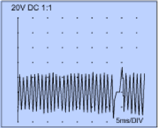
We see that there is one full cycle up and down for each tooth of the flywheel ring, and a gap where one tooth is missing. Wikipedia and other sites indicate that CPS units that produce waveforms like this are inductive sensors. A general car diagnosis web site I found had a very similar waveform. Both show the waveform about 6, 8, 10 V peak to peak. The DME unit detects crank position by finding the waveform's zero crossing and it knows where the missing tooth on the flywheel ring is by the gap.
But now here is the waveform from my CPS. I got this by pinching a very thin wire into pin 1 of the CPS connector and running that into an oscilloscope, with ground taken from the engine case nearby. Note:
Note that this photo unavoidably has a bright part of the scope scan where the camera shutter was open, and the rest of the waveform is shown dimly from the leftover phosphor glow. The picture shows slightly more than 2 full flywheel rotations.
So the question is, is my CPS bad? Does anyone know what these waveforms really look like in practice?
So I can imagine that if my CPS is producing a small fraction of the voltage it should be, heat, low voltage, or other issues may prevent the DME from reliably detecting the waveform's zero crossings.
It appears that I had two separate issues. First was a bad alternator, and that appears to be addressed (after two alternators).
But the remaining symptoms are still there: very jerky after the engine gets fully up to operating temp. It feels like the rev limiter kicks in but at rapidly lower RPMs. It first starts after 15-20 minutes of stop-and-go driving and I turn on the AC and rear window defroster to make it happen sooner. The RPM is at around 3k when it first starts. But within 2-3 minutes more it kicks in just starting from a stop, like 1k RPM and shudders throughout the range. Another couple of minutes and it's completely undrivable.
No problem at all when cold.
Durametric shows that the DME consistently throws P0336, "ref mark sensor", the crankshaft position sensor (CPS), when this happens. When it gets really bad it also throws various cylinder misfires (from both banks) and sometimes even the ABS/PSM warning lights go on. It's a whole engine phenomenon, not one bank or one cylinder.
So the logical culprit would appear to be the CPS. There are numerous reports on this forum and others about heat sensitivity of a failing CPS.
I spent the day today researching and measuring my CPS. I am not sure how to interpret the results and wonder if anybody here has gone through this, especially looking at the waveforms.
First, the wiring diagram shows 3 pins:
1. The signal
2. Ground
3. Shield (protect against electromagnetic interference)
At room temp the resistance between 1 and 2 should be between 800 and 1000 ohms according to Porsche diagnostic manual, and I measured 935. So that's OK. I also measured resistance between the harness pins and they were either 45k or 7k; no dead shorts and no opens, there are no specs here but I guess those are not obviously bad.
I heated up the CPS in a toaster oven (protected by foil) to around 190 F and it measured about 1.2k; a little higher as you'd expect but not an open circuit or short or something.
Then I measured the expected distance from the tip of the sensor when mounted in the engine case to the flywheel teeth using a depth gauge. As far as I can tell it ended up about 0.8 mm (30 mils) which seems rather small. One thing I tried was to add thin spacers to increase the distance; I'm currently running with spacers that roughly brought space to 1.5 mm (60 mils), and it is hard to know if it's doing better or not; in any case the difference is subtle.
More importantly I have some waveform images. First is an image of what the Porsche diagnostic manual says the waveform of the sensor pin 1 should look like.
We see that there is one full cycle up and down for each tooth of the flywheel ring, and a gap where one tooth is missing. Wikipedia and other sites indicate that CPS units that produce waveforms like this are inductive sensors. A general car diagnosis web site I found had a very similar waveform. Both show the waveform about 6, 8, 10 V peak to peak. The DME unit detects crank position by finding the waveform's zero crossing and it knows where the missing tooth on the flywheel ring is by the gap.
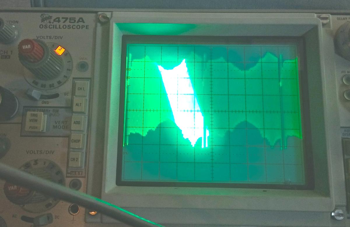
But now here is the waveform from my CPS. I got this by pinching a very thin wire into pin 1 of the CPS connector and running that into an oscilloscope, with ground taken from the engine case nearby. Note:
- Wide variation in voltage, more than a factor of 2
- Peak-to-peak voltage only 0.6 - 1.2 V! (Note the scope is at 0.2 V/div)
Note that this photo unavoidably has a bright part of the scope scan where the camera shutter was open, and the rest of the waveform is shown dimly from the leftover phosphor glow. The picture shows slightly more than 2 full flywheel rotations.
So the question is, is my CPS bad? Does anyone know what these waveforms really look like in practice?
So I can imagine that if my CPS is producing a small fraction of the voltage it should be, heat, low voltage, or other issues may prevent the DME from reliably detecting the waveform's zero crossings.
 06-22-2014, 03:02 AM
#2
Hi Mike, the sensor is an inductive sensor like you said and it has a magnet inside. It generates ac voltage between the 2 pins as the teeth of the flywheel approach and leave the sensor. The third pin provides a shield connected to the ground. The proper way to measure the sensor output signal therefore is to set the scope for ac coupling and measure the voltage generated between pin 1 and pin 2, and not pin1 and chassis of the car.
Also, be careful measuring the resistance of the harness side with the DME still connected as you are sending electricity to the DME.
The full diagnostic of code P0336 should call for removing the DME and check the continuity between pin 1 of sensor and pin 32 (plug III) of DME, then pin 2 of sensor and pin 46 (plug III) of the DME. Also check resistance between pins 1&3, then 2&3, of the sensor. They should read infinity. If those check out, replace the sensor.
06-22-2014, 03:34 AM
#3
Btw, I agree the sensor seems bad if it can only generate 0.6 to 1.2v peak-to-peak. Too bad my car is on the lift now and can't be started for a few days. I would have checked what mine looks like.
06-22-2014, 01:16 PM
#4
Instructor
Thread Starter
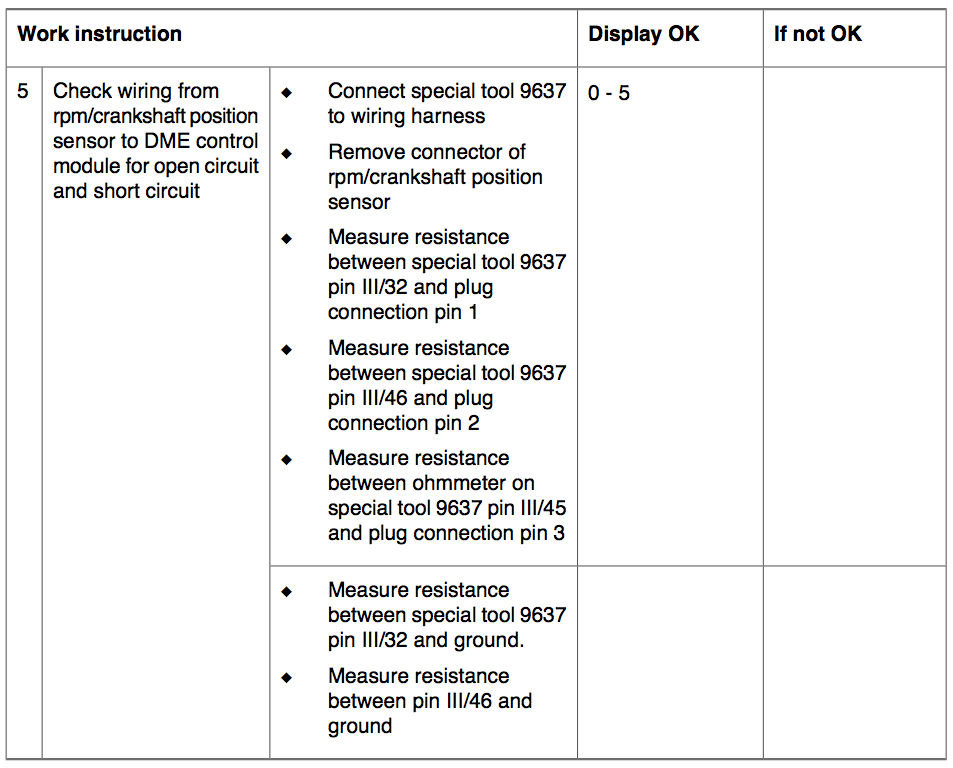
The full diagnostic of code P0336 should call for removing the DME and check the continuity between pin 1 of sensor and pin 32 (plug III) of DME, then pin 2 of sensor and pin 46 (plug III) of the DME. Also check resistance between pins 1&3, then 2&3, of the sensor. They should read infinity. If those check out, replace the sensor.
There are actually five continuities specified: III/32 to pin 1, III/45 to pin 3, III/46 to pin2, III/32 to ground, and III/46 to ground. All of these should be in the range 0 - 5 ohms. Note that the pin numbers are reversed from the sensor connector; I guess the harness is numbered the other way around??
Anyway if this is correct and pin 2 is actually ground (and the shield is grounded at the DME), then I got the full voltage measured.
Here's the page from the diagnostics manual:
 06-22-2014, 01:21 PM
#5
Race Director

If you suspect the CPS why not just replace it? While generally I do not like to throw parts at a symptom if the part is not very expensive or hard to get at sometimes it is quicker to just throw in the new part.
BTW, I am not convinced the sensor is at fault.
They generally work or they don't work.
The behavior still reminds me of an electrical problem, the electrical system -- battery, alternator, wiring -- is not able to provide the engine and the rest of the car with sufficient electrical power when the engine is running.
I know you have been through 2 alternators and I believe also replaced some very questionable wiring/cabling, but I still think the symptoms are electrical power related.
However, you are certainly free to suspect the CPS and continue your diagnosis with the CPS as suspect #1.
06-22-2014, 01:40 PM
#6
Instructor
Thread Starter
If you suspect the CPS why not just replace it? While generally I do not like to throw parts at a symptom if the part is not very expensive or hard to get at sometimes it is quicker to just throw in the new part.
BTW, I am not convinced the sensor is at fault.
They generally work or they don't work.
The behavior still reminds me of an electrical problem, the electrical system -- battery, alternator, wiring -- is not able to provide the engine and the rest of the car with sufficient electrical power when the engine is running.
I know you have been through 2 alternators and I believe also replaced some very questionable wiring/cabling, but I still think the symptoms are electrical power related.
However, you are certainly free to suspect the CPS and continue your diagnosis with the CPS as suspect #1.
BTW, I am not convinced the sensor is at fault.
They generally work or they don't work.
The behavior still reminds me of an electrical problem, the electrical system -- battery, alternator, wiring -- is not able to provide the engine and the rest of the car with sufficient electrical power when the engine is running.
I know you have been through 2 alternators and I believe also replaced some very questionable wiring/cabling, but I still think the symptoms are electrical power related.
However, you are certainly free to suspect the CPS and continue your diagnosis with the CPS as suspect #1.
Yes it is possible it is still an electrical power problem but I would be at a loss to figure out what it is. Belt slippage when hot? It's a new belt and supposedly the tensioner is an either-or failure, not by degree.
Maybe I should watch the 12V supply and see if there are glitches. I measured voltage drops all around the charging system -- but not under heavy load -- and saw all very low drops. Ground between alternator and battery was only 25 mV. Worst B+ drop was alternator to battery, 150 mV.
06-22-2014, 02:08 PM
#7
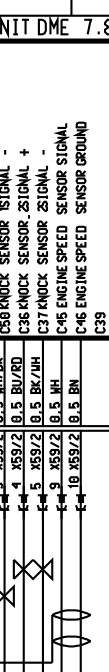
Ahsai, thanks. I should have done that but ended up doing the single-sided measurement because the wiring diagram shows DME pin III/46 labeled GND and using a brown wire, while III/45 is labeled SIGNAL (see image below). If the sensor produces AC (which it certainly should) then I would presume that what I measured was half the AC voltage, offset by some DC. However.....
Attachment 846205
OK I should do the full set of diagnosis steps. I've never taken the DME out before so it's a new thing.
There are actually five continuities specified: III/32 to pin 1, III/45 to pin 3, III/46 to pin2, III/32 to ground, and III/46 to ground. All of these should be in the range 0 - 5 ohms. Note that the pin numbers are reversed from the sensor connector; I guess the harness is numbered the other way around??
Anyway if this is correct and pin 2 is actually ground (and the shield is grounded at the DME), then I got the full voltage measured.
Here's the page from the diagnostics manual:
Attachment 846206
Removing the DME is very easy. You just need to remove plug III. There's a lever lock to unclip and remove in one motion. Just make sure you disconnect the battery and you should be fine.
I'm curious to see what you find.
Trending Topics
06-22-2014, 02:16 PM
#8
If you suspect the CPS why not just replace it? While generally I do not like to throw parts at a symptom if the part is not very expensive or hard to get at sometimes it is quicker to just throw in the new part.
BTW, I am not convinced the sensor is at fault.
They generally work or they don't work.
The behavior still reminds me of an electrical problem, the electrical system -- battery, alternator, wiring -- is not able to provide the engine and the rest of the car with sufficient electrical power when the engine is running.
I know you have been through 2 alternators and I believe also replaced some very questionable wiring/cabling, but I still think the symptoms are electrical power related.
However, you are certainly free to suspect the CPS and continue your diagnosis with the CPS as suspect #1.
BTW, I am not convinced the sensor is at fault.
They generally work or they don't work.
The behavior still reminds me of an electrical problem, the electrical system -- battery, alternator, wiring -- is not able to provide the engine and the rest of the car with sufficient electrical power when the engine is running.
I know you have been through 2 alternators and I believe also replaced some very questionable wiring/cabling, but I still think the symptoms are electrical power related.
However, you are certainly free to suspect the CPS and continue your diagnosis with the CPS as suspect #1.
I also agree that the drivability issues may or may not be related to this code.
Btw, Mike can you measure the B+ jump start terminal (since it's easy to access) and the ground chassis for the ac output of the alternator? It should be way less than 1v p-2-p.
06-22-2014, 03:42 PM
#9
Instructor
Thread Starter
OK, back from errands and have the rest of the day to work on this. Plan of attack:
1. Prep:
* Disconnect harness at DME and CPS, inspect, measure all possible resistances between 3 CPS wires and ground at DME
* Reconnect CPS, measure same resistances at DME with CPS in
* See if I can squeeze two wires in to CPS connectors at DME for scoping
2. Reconnect and run engine until hot and shows P0336
* Monitor AC voltage throughout (from cold to hot) at jump terminal, look for glitches
* Monitor CPS signal, hopefully at DME
* Let's see if I can trigger scope on B+ glitch and see if CPS signal looks odd
* Turn engine off, disconnect DME, measure CPS resistances with CPS connected
BTW is there any way to bump the throttle from outside the car? Durametric?
06-22-2014, 07:31 PM
#10
Instructor
Thread Starter
OK, pretty sure I have the smoking gun. It's the CPS.
I have the following measurements:
1) At the DME connector, with CPS in:
Pins III/45 - III/46: 932 ohms (resistance of CPS windings)
All other combinations of pins III/45, III/46, III/32, and ground are infinite
2) Between DME connector and CPS harness:
III/45 - 1, III/46 - 2, and III/32 - 3: 0.4 - 0.5 ohms
All other combinations are infinite
OK so there are no shorts, no opens, the harness appears fine, the connectors all look good, no burnt wires or insulation (I opened up the big wiring mess under the center of the rear between the DME and the relay panel to look). BTW I had to remove all the DME connectors because the shield goes to another connector, IV I guess.
I left in a couple of very small wires (wire wrap wires for those of you who remember) sticking out of pins III/45 and III/46 at the DME to hook up the scope. I hooked up the other scope input to the alternator as well as a DVM measuring AC as Ahsai suggested.
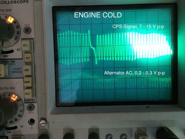
Engine is cold. I started up the car and looked at the scope. That's the first image. Everything looks great! Top trace is CPS at 5V/div: CPS is outputting between 7 and 15 V today (some discrepancy could definitely have been because I was measuring against ground yesterday)! Bottom trace is alternator output at jump point, in AC mode, 0.2 V/div. AC on the DVM starts at about 100 mV and when idle settles to 680 RPM, AC drops to 50-60 mV.
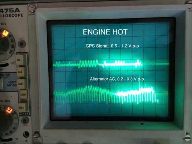
I turn on AC and rear defroster and let it warm up. Still looking good.... go inside for a quick chat with the spouse (ummm, no such thing, never quick). Come back out because the sound seems a little rougher. Oh my. The CPS signal has dropped down to 1/10 of what it was before. This is what I saw yesterday. See the second image. I am amazed the DME can make sense of this signal!
To confirm that I didn't just lose the signal somehow, I will let the engine cool an hour or two and look at the CPS signal again.
DC voltage at the jump point while idling ranged 12.2 - 12.9 depending on when (cold was higher) and how many accessories were on. It varied and rose and fell, was not constantly dropping.
I have the following measurements:
1) At the DME connector, with CPS in:
Pins III/45 - III/46: 932 ohms (resistance of CPS windings)
All other combinations of pins III/45, III/46, III/32, and ground are infinite
2) Between DME connector and CPS harness:
III/45 - 1, III/46 - 2, and III/32 - 3: 0.4 - 0.5 ohms
All other combinations are infinite
OK so there are no shorts, no opens, the harness appears fine, the connectors all look good, no burnt wires or insulation (I opened up the big wiring mess under the center of the rear between the DME and the relay panel to look). BTW I had to remove all the DME connectors because the shield goes to another connector, IV I guess.
I left in a couple of very small wires (wire wrap wires for those of you who remember) sticking out of pins III/45 and III/46 at the DME to hook up the scope. I hooked up the other scope input to the alternator as well as a DVM measuring AC as Ahsai suggested.
Engine is cold. I started up the car and looked at the scope. That's the first image. Everything looks great! Top trace is CPS at 5V/div: CPS is outputting between 7 and 15 V today (some discrepancy could definitely have been because I was measuring against ground yesterday)! Bottom trace is alternator output at jump point, in AC mode, 0.2 V/div. AC on the DVM starts at about 100 mV and when idle settles to 680 RPM, AC drops to 50-60 mV.
I turn on AC and rear defroster and let it warm up. Still looking good.... go inside for a quick chat with the spouse (ummm, no such thing, never quick). Come back out because the sound seems a little rougher. Oh my. The CPS signal has dropped down to 1/10 of what it was before. This is what I saw yesterday. See the second image. I am amazed the DME can make sense of this signal!
To confirm that I didn't just lose the signal somehow, I will let the engine cool an hour or two and look at the CPS signal again.
DC voltage at the jump point while idling ranged 12.2 - 12.9 depending on when (cold was higher) and how many accessories were on. It varied and rose and fell, was not constantly dropping.
The following users liked this post:
996.2 (07-20-2019)
06-22-2014, 08:47 PM
#11
 Excellent diagnostic with very satisfying results and findings
Would be great if you can leave those connections there and retest with the new CPS but I'm pretty sure you nailed it already.
06-22-2014, 09:28 PM
#13
Instructor
Thread Starter
Thanks guys for the help and guidance. Now maybe I can actually drive my car for real after shipping it off in January! Replacement CPS is arriving under "warranty".
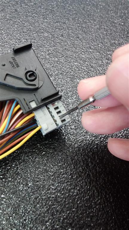
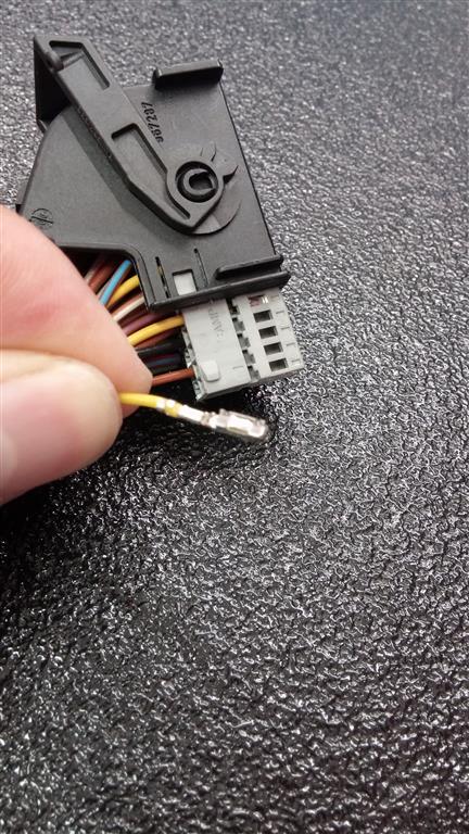
I actually thought about leaving the connections but they were really intended to be (very) temporary and not disturbed. Still, it wasn't that difficult to put them in. Did you know you can easily disassemble the DME connector III into separate 26-pin connectors and have easy access to the wires and female connector pieces?
I actually thought about leaving the connections but they were really intended to be (very) temporary and not disturbed. Still, it wasn't that difficult to put them in. Did you know you can easily disassemble the DME connector III into separate 26-pin connectors and have easy access to the wires and female connector pieces?
06-22-2014, 10:31 PM
#14
Yes those black and grey inserts that house the pins just push out after you pry the locking tabs on the outer housing gently. Once you remove the inserts, the pins can be removed by pressing down the small triangular part of the pin with the smallest eyeglass screwdriver. Press the triangular part and pull the wire gently then the pin will catch again at the second locking slit. You press the triangular part again to clear that. Super easy.
Last edited by Ahsai; 06-22-2014 at 11:01 PM.
06-22-2014, 11:22 PM
#15
Btw, you said your jumper terminal voltage varies from 12.2 to 12.9 at idle? That sounds a little low even after fully warmed up. The instrument cluster voltmeter is reading the same?