When you click on links to various merchants on this site and make a purchase, this can result in this site earning a commission. Affiliate programs and affiliations include, but are not limited to, the eBay Partner Network.
First time doing the process on a 01 911 C2.
Setup bank 1, rotated 360 then added cams to bank 2 and buttoned it all up. Rotating the crank, I notice the vario-cam solenoid hopping. Made a video at the link below to show the behavior.
How r u holding the cams in place while rotating the motor? I dont think u r suppose to spin it without them. The lifters will cause them to jump around expecially the intake one. There is no way to hold it on the far side. check the dots on the cams. U shulld be able to count 14 links to the next dot. I just did this last night for my variocam pads.
Thanks for chiming in.
Holding with the cam holder tool on the other end of each bank.
14 links? You have 3.4? There are only 7 (maybe 8) links between each colored link.
3 chain engine vs 5 chain engine? BTW, DeJeeper is referring to links between the dots on the cam gears, whereas the OP is referring to links between the colored links on the cam chains.
Mine is a 5 chain. I guess i mean 14 hollow areas that the gear tooth would go into. Zoom in u can see the dots on the gears and u can count the links or spaces. My old and new chains did not have the colored links.
Count the Rollers or Pins, like DeJeeper says, 14 is the Magic number. The colored links are only for initial installation, after a revolution they will not line back up except every now and then (mathematical equation).
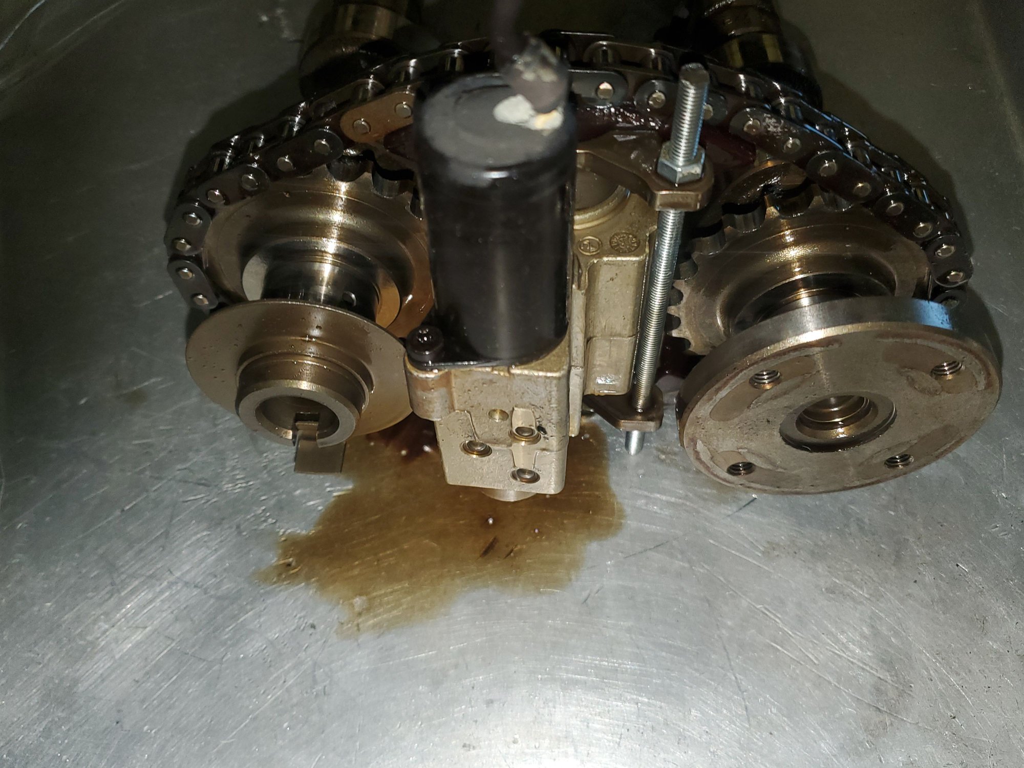
Also notice the relief on the intake cam in my pic. When put on the head it will point at the block for 4-6 and cover for 1-3. On the other side of the exhaust cam the slot will be 90* of that relief and should accept the cam locking tool.
You've got to support those cams in the middle before you snap them! The spring are putting a huge pressure on the cast iron camshafts and they are not mean to bend. The cam holder at the end is not enough if you are spinning the camshafts around. A small piece of hardwood with some long bolts (2 on each cam) will do the trick.
Thanks doug996inkc
I have that assembly and will put it on. Was not sure it was safe to rotate with that on as it's not the bearing in contact with the cam.
I can certainly put cam cover back on but want to see that everything is rotating correctly.

 01-30-2021, 10:51 PM