OEM Manual Rotary Switch to Turn on Cooling Fans
 10-24-2020, 10:44 PM
#1
Burning Brakes
Thread Starter
Rotary Switch to Manually Turn on the Cooling Fans Porsche 996/986

So the rotary switch has a fan symbol that lights up the same colour as the rest of the buttons in the car when the headlights are turned on. To turn on the low speed fans, rotate the dial up and the symbol lights up blue. Turn it down for the high speed (and the engine fan as well) and it turns red.
The automatic function of the fans is not affected by this at all. In fact, the indicator lights will turn on when the car switches the fans on, so you can tell when the high or low speeds are on, which is cool.
So the function of the rotary switch will be:
-when at rest and headlights/parking lights are not on, fans are not on and the indicator light is not on.
-when the dial is turned up, low speed fans are on and the indicator light illuminates blue.
-when the dial is turned down, the high speed fans are on along with the engine bay fan and the indicator light illuminates red.
-when the headlights/parking lights are on, the indicator lights orange.
We will need 1 RGB LED, 1 diode, 1 resistor of 500 ohms, 1 resistor of 1000 ohms, 1 resistor of 5000 ohm (this may be different depending on the LED you use)
Here is the wiring diagram that we will follow to make this work.

First you need the headlight level switch. It was available only on the 996.1 cars and is part number:
996 613 230 01
You need to disassemble it, as all the circuitry inside will be replaced, and the headlight symbol removed.


Remove the circuit board now, as it will be replaced with one we will make from scratch. Remove the LED as well and all wiring inside.
Now you need to make a new circuit board to replace the old one.
You need to visit an electronics store and get Ferric Chloride and copper clad board.


Cut a piece of board to match the size of the old circuit board. Cut it roughly with a saw and then use a file to get it down to exactly the shape and size you need. Peel off the protective film and then lightly sand off the bluish film off the board until you have only copper exposed.


Now you need to draw on the circuit onto the copper with a sharpie. I did it backwards, but it is soo much easier if you sand off the blue film and then draw the circuit.


The chip will now go into the Ferric Chloride. The liquid will eat away all of the copper except for the parts you drew in sharpie, as the liquid does not react with it, leaving the copper underneath protected. When you take it out of the Ferric Chloride, you will have your chip.
Clean off the sharpie with rubbing alcohol. Now you will drill 3 small holes in the bottom of the chip for wires to attach to.


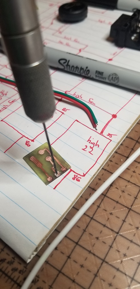
You will need to solder in bare solid wire into each of the holes. One contact will be for high speed, one for low speed and one for ground. Here you see the chip in place with the wires leading out of it.


Each wire will need to be soldered onto a contact in the switch that leads to a pin.

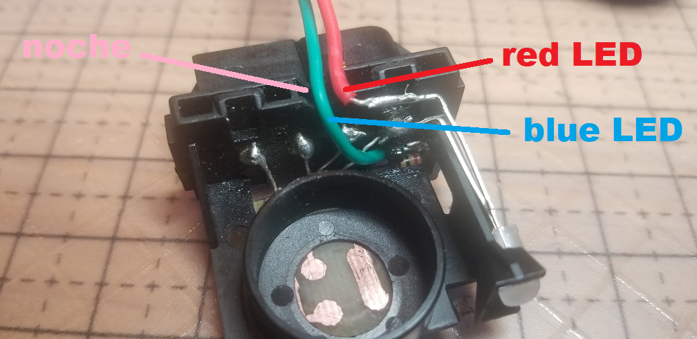
Now for the LED. You need a frosted 5mm tri colour RGB LED with a common cathode.

The ground for the LED will go to pin 4 in the switch - same as the grounds for the high and low speed for the fans. The lead for the green will go to the 3rd pin.

There is not enough pins for everything, so you will need to add more. I did this by putting a noche in the base of the switch to allow a couple wires to run out of the switch to another connector. I just picked up a male/female 2 pin connector from ebay like the one below.

You will need resistors for these LEDs. Green is much stronger than red, so I used a 500 ohm resistor in series for the red LED, and 5000 ohm resistor in series for the green LED. 1000for the blue. You will need to test the light intensity and how the colours mix to get you the orange you need using different strengths of resistors to match the rest of your buttons. There is not much room inside the switch, so I placed my resistors and the diode outside the switch, which you can see here.

Next is to make the fan symbol. Sand off the headlight symbol from the indicator piece. I had a tiny fan laser cut by a shop for me onto vinyl, which I then placed on the piece and painted black. Removed the vinyl, and now there is a perfect symbol of a fan that the LEDs will illuminate.

Place back in the switch and now put it all back together. Switch is done. Now to wire everything up to the switch.


The diode has to go where you see it in the diagram. It allows current only in one direction. Again, there is no room for it in the switch, so I have it in the wiring outside the switch. The diode will allow current to flow from the power supply for green LED to the red LED (this will make orange). You may need to test different resistor values to get the right colour of orange.

Now to make it all work. We will need four 12v relays. I installed all 4 relays in the relay tray above the fuse box to make it look as OEM as possible. But they could go anywhere. You will need 4 relay plug with the metal connectors if you do what I did. Part number is 928 610 511 00.
You need to locate the 2 low speed fan relays and the 2 high speed. The low speed relays are numbers 19 and 21, while the high speed relays are 20 and 22.
Disconnect the battery in the car.
First remove the fuse box panel. It is held on by 4 screws. You can then just pull it out. The relay box is above it. It is best to remove the relay box. It is held in place with a single nut, and clipped in on the opposite end.


Flip the relay tray around so you have access to the back. I removed plugs that were in my way.

Now use the wiring diagram from earlier to make the wiring connections you need. The proper routing and connections of the new wiring is all there in the diagram. The relays labeled as normally open or normally closed are the new relays you are adding. The purpose of these relays is to turn on and off the appropriate LED colour to indicate whether high or low is on, and to turn off the orange (if headlights are switched on) when fans are in operation.
If you want the engine bay fan to also turn on with the high speed fans, then you will need to run a wire splitting off from the wire runs from pin 85 from relay 22 all the way to the back behind the rear passenger. There is another relay box there. I removed the rear quarter interior panel to help with running the wire as well as the bonnet/engine cover release panel trim. But you don’t have to, just tuck the wire in.
Remove the carpet in the back to expose the relay box. It is on the right and is held in place with a nut in the centre and 2 screws on the right. You can see the wire I ran from the front.

Flip it over and find relay number 8. You want to tap into pin 85 of that relay.

Put it all back together. Now wire up the switch.
The wire from pin 85 from relay 22 goes to pin 1 of your plug for the switch.
The wire from pin 85 from relay 21 goes to pin 2.
The wire from pin 87a from the normally closed low speed relay (see diagram) goes to pin 3.
The wire from pin 87 from the normally open low speed relay (see diagram) goes to the connector you added to the switch - green wire
The wire from pin 87 from the normally open high speed relay (see diagram) goes to the connector you added to the switch - red wire
From the switch, we have a ground wire. This can go to any ground point in the dash. I found a spot close to where the switch goes and grounded it there.
There is one last wire, and this is to get power to the red/green LED when the headlights are on. You can wire this to any switch in the car that illuminates. I took power for this from the intermittent wiper in the dash for power.
Now with everything wired up, this should work.
With the car on, but no headlights and the switch is at rest, there should be nothing. When the headlights are turned on, you should have the fan symbol light up in orange. Turn on the high speed fans, and you should have the engine fan and the 2 front fans on and the symbol should be red. On low speed, only the 2 front fans will be on at low speed and the symbol should light up in blue.
The car will still turn on the fans automatically, and when it does, the fan symbol will also light up to let you know the car has turned on the fans at either high or low.


So the rotary switch has a fan symbol that lights up the same colour as the rest of the buttons in the car when the headlights are turned on. To turn on the low speed fans, rotate the dial up and the symbol lights up blue. Turn it down for the high speed (and the engine fan as well) and it turns red.
The automatic function of the fans is not affected by this at all. In fact, the indicator lights will turn on when the car switches the fans on, so you can tell when the high or low speeds are on, which is cool.
So the function of the rotary switch will be:
-when at rest and headlights/parking lights are not on, fans are not on and the indicator light is not on.
-when the dial is turned up, low speed fans are on and the indicator light illuminates blue.
-when the dial is turned down, the high speed fans are on along with the engine bay fan and the indicator light illuminates red.
-when the headlights/parking lights are on, the indicator lights orange.
We will need 1 RGB LED, 1 diode, 1 resistor of 500 ohms, 1 resistor of 1000 ohms, 1 resistor of 5000 ohm (this may be different depending on the LED you use)
Here is the wiring diagram that we will follow to make this work.
First you need the headlight level switch. It was available only on the 996.1 cars and is part number:
996 613 230 01
You need to disassemble it, as all the circuitry inside will be replaced, and the headlight symbol removed.
Remove the circuit board now, as it will be replaced with one we will make from scratch. Remove the LED as well and all wiring inside.
Now you need to make a new circuit board to replace the old one.
You need to visit an electronics store and get Ferric Chloride and copper clad board.
Cut a piece of board to match the size of the old circuit board. Cut it roughly with a saw and then use a file to get it down to exactly the shape and size you need. Peel off the protective film and then lightly sand off the bluish film off the board until you have only copper exposed.
Now you need to draw on the circuit onto the copper with a sharpie. I did it backwards, but it is soo much easier if you sand off the blue film and then draw the circuit.
The chip will now go into the Ferric Chloride. The liquid will eat away all of the copper except for the parts you drew in sharpie, as the liquid does not react with it, leaving the copper underneath protected. When you take it out of the Ferric Chloride, you will have your chip.
Clean off the sharpie with rubbing alcohol. Now you will drill 3 small holes in the bottom of the chip for wires to attach to.
You will need to solder in bare solid wire into each of the holes. One contact will be for high speed, one for low speed and one for ground. Here you see the chip in place with the wires leading out of it.
Each wire will need to be soldered onto a contact in the switch that leads to a pin.
Now for the LED. You need a frosted 5mm tri colour RGB LED with a common cathode.
The ground for the LED will go to pin 4 in the switch - same as the grounds for the high and low speed for the fans. The lead for the green will go to the 3rd pin.
There is not enough pins for everything, so you will need to add more. I did this by putting a noche in the base of the switch to allow a couple wires to run out of the switch to another connector. I just picked up a male/female 2 pin connector from ebay like the one below.
You will need resistors for these LEDs. Green is much stronger than red, so I used a 500 ohm resistor in series for the red LED, and 5000 ohm resistor in series for the green LED. 1000for the blue. You will need to test the light intensity and how the colours mix to get you the orange you need using different strengths of resistors to match the rest of your buttons. There is not much room inside the switch, so I placed my resistors and the diode outside the switch, which you can see here.
Next is to make the fan symbol. Sand off the headlight symbol from the indicator piece. I had a tiny fan laser cut by a shop for me onto vinyl, which I then placed on the piece and painted black. Removed the vinyl, and now there is a perfect symbol of a fan that the LEDs will illuminate.
Place back in the switch and now put it all back together. Switch is done. Now to wire everything up to the switch.
The diode has to go where you see it in the diagram. It allows current only in one direction. Again, there is no room for it in the switch, so I have it in the wiring outside the switch. The diode will allow current to flow from the power supply for green LED to the red LED (this will make orange). You may need to test different resistor values to get the right colour of orange.
Now to make it all work. We will need four 12v relays. I installed all 4 relays in the relay tray above the fuse box to make it look as OEM as possible. But they could go anywhere. You will need 4 relay plug with the metal connectors if you do what I did. Part number is 928 610 511 00.
You need to locate the 2 low speed fan relays and the 2 high speed. The low speed relays are numbers 19 and 21, while the high speed relays are 20 and 22.
Disconnect the battery in the car.
First remove the fuse box panel. It is held on by 4 screws. You can then just pull it out. The relay box is above it. It is best to remove the relay box. It is held in place with a single nut, and clipped in on the opposite end.
Flip the relay tray around so you have access to the back. I removed plugs that were in my way.
Now use the wiring diagram from earlier to make the wiring connections you need. The proper routing and connections of the new wiring is all there in the diagram. The relays labeled as normally open or normally closed are the new relays you are adding. The purpose of these relays is to turn on and off the appropriate LED colour to indicate whether high or low is on, and to turn off the orange (if headlights are switched on) when fans are in operation.
If you want the engine bay fan to also turn on with the high speed fans, then you will need to run a wire splitting off from the wire runs from pin 85 from relay 22 all the way to the back behind the rear passenger. There is another relay box there. I removed the rear quarter interior panel to help with running the wire as well as the bonnet/engine cover release panel trim. But you don’t have to, just tuck the wire in.
Remove the carpet in the back to expose the relay box. It is on the right and is held in place with a nut in the centre and 2 screws on the right. You can see the wire I ran from the front.
Flip it over and find relay number 8. You want to tap into pin 85 of that relay.
Put it all back together. Now wire up the switch.
The wire from pin 85 from relay 22 goes to pin 1 of your plug for the switch.
The wire from pin 85 from relay 21 goes to pin 2.
The wire from pin 87a from the normally closed low speed relay (see diagram) goes to pin 3.
The wire from pin 87 from the normally open low speed relay (see diagram) goes to the connector you added to the switch - green wire
The wire from pin 87 from the normally open high speed relay (see diagram) goes to the connector you added to the switch - red wire
From the switch, we have a ground wire. This can go to any ground point in the dash. I found a spot close to where the switch goes and grounded it there.
There is one last wire, and this is to get power to the red/green LED when the headlights are on. You can wire this to any switch in the car that illuminates. I took power for this from the intermittent wiper in the dash for power.
Now with everything wired up, this should work.
With the car on, but no headlights and the switch is at rest, there should be nothing. When the headlights are turned on, you should have the fan symbol light up in orange. Turn on the high speed fans, and you should have the engine fan and the 2 front fans on and the symbol should be red. On low speed, only the 2 front fans will be on at low speed and the symbol should light up in blue.
The car will still turn on the fans automatically, and when it does, the fan symbol will also light up to let you know the car has turned on the fans at either high or low.
Last edited by jim010; 10-24-2020 at 10:51 PM.

The following 12 users liked this post by jim010:
circuit.heart (01-06-2024),
Csabix (01-05-2024),
damage98MO (05-27-2022),
golock911 (10-26-2020),
James_03C4S (10-25-2020),
and 7 others liked this post.
10-25-2020, 06:12 AM
#2
Great idea. Excellent execution and thank you for the detailed how-to!
10-25-2020, 10:11 AM
#3
Even though I am not planning on doing this, I felt like I wanted to try it anyway. Fascinated and I learned a lot. This is the stuff that makes this forum absolute gold....thanks for sharing!
10-25-2020, 11:38 AM
#4
Racer
That's a pretty impressive project. Well executed and detailed description. Well done.


Trending Topics
10-25-2020, 08:50 PM
#8
Instructor
Pretty cool. How does the ECM control the fans? If the Porsche ECM just grounds the fan relays to activate the fans then perhaps you could just find that grounding wire to the relay and have your switch ground it. That's what I did on another vehicle I owned but I'm not sure how the Porsche ECM like to control the fans and relays.
10-25-2020, 10:15 PM
#9
Burning Brakes
Thread Starter
Thanks guys.
I hope someone might be inspired to try this themselves.
James, if you check the wiring diagram I provided in the post, you will see the switch takes the wires from the ground side of the relay to turn the fans on. All the complicated wiring is to make the indicator LEDs work. A much less complcated option wiring wise would be to use an Arduino module, but I am not familiar with programming those.
Last edited by jim010; 10-25-2020 at 10:24 PM.
The following users liked this post:
James_03C4S (10-26-2020)
10-26-2020, 02:24 AM
#10
RL Community Team
Rennlist Member
Rennlist Member
Wow, I may have to try this.
I‘ve thought about adding a couple of switches to my batwing, but I prefer this.
Very clean look!
I‘ve thought about adding a couple of switches to my batwing, but I prefer this.
Very clean look!
10-26-2020, 10:43 AM
#11
Rennlist Member
I'll add another WOW! Mighty impressive - a massive amount of work for what will/may be perceived by many as "of questionable value" or "downright unnecessary". The fact that you (and your wife - she must be a saint,or as crazy as you) committed to the idea and followed through with it is a real testament to perseverance! 
10-26-2020, 11:00 AM
#13
Burning Brakes
Thread Starter
I'll add another WOW! Mighty impressive - a massive amount of work for what will/may be perceived by many as "of questionable value" or "downright unnecessary". The fact that you (and your wife - she must be a saint,or as crazy as you) committed to the idea and followed through with it is a real testament to perseverance!
It no longer became about 'do we need this', but turned into 'can we figure this out'. It was a challenge, and we picked up alot of new skills.
It was fun to solve this challenge, and it looks cool in the car. I like that the indicator turns on whether the fans are on manually, or whether the car turns them on.
I will say this - I have a new appreciation for the designers of switches and buttons ...
The following 2 users liked this post by jim010:
damage98MO (05-27-2022),
dporto (10-26-2020)
10-26-2020, 12:01 PM
#14
Just curious, is that switch the same size as the the ones in the console?
10-26-2020, 12:05 PM
#15
Burning Brakes
Thread Starter