When you click on links to various merchants on this site and make a purchase, this can result in this site earning a commission. Affiliate programs and affiliations include, but are not limited to, the eBay Partner Network.
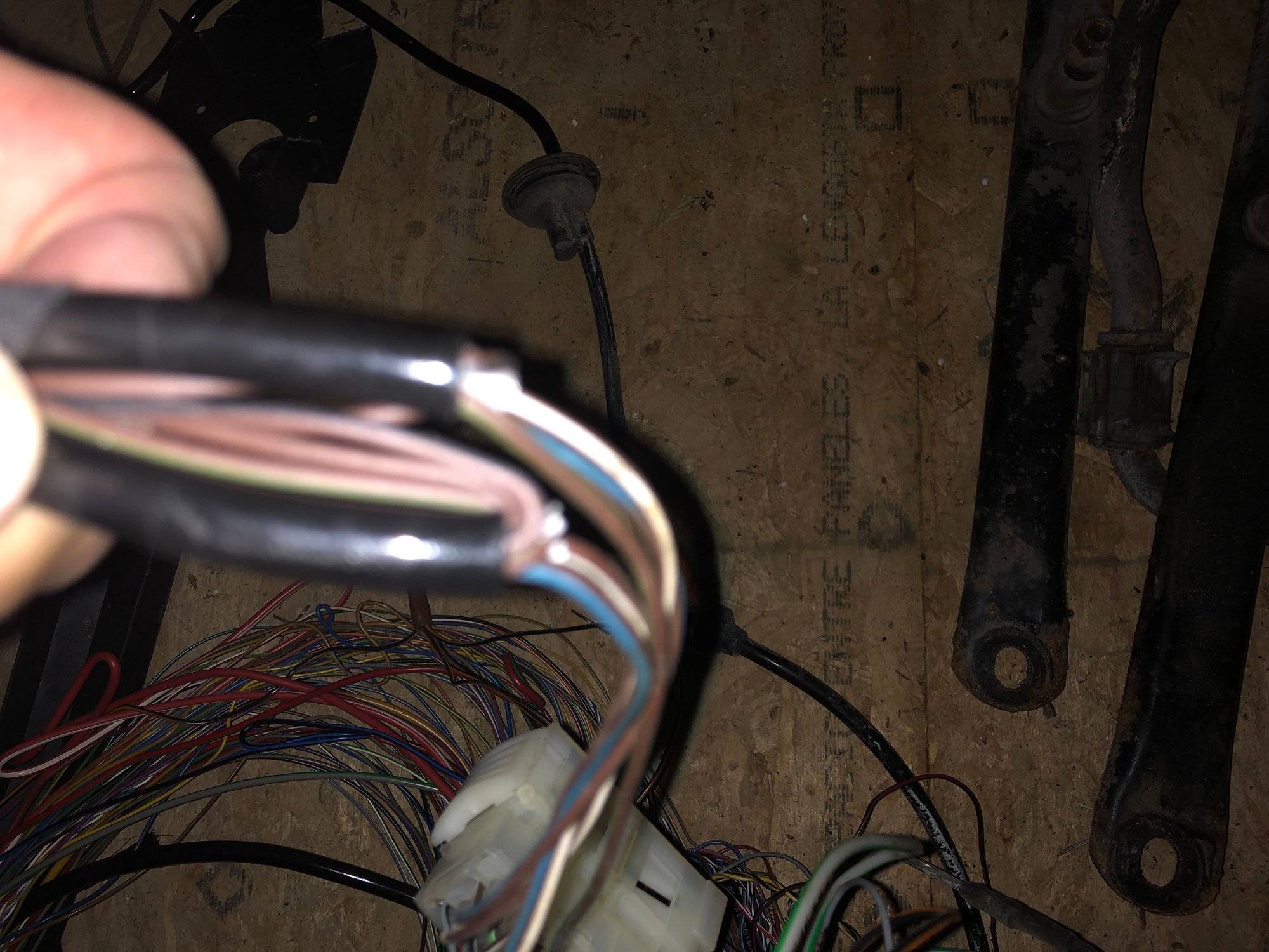
A week ago my brake pad warning light went off so I picked up F/R Textar pads and four new pad wear sensors. Everything was going fine until I popped open the metal locking mechanism that secures the ABS/brake pad wear indicator plugs and started gently pulling out the old BP sensor connection on the Right-Rear. I noticed some black plastic bits on the ground directly under the axle so I grabbed a LED headlamp and peered over the rotor for a better look. The connector housing was literally destroyed. The metal retaining clip was basically holding 20 cracked pieces together.
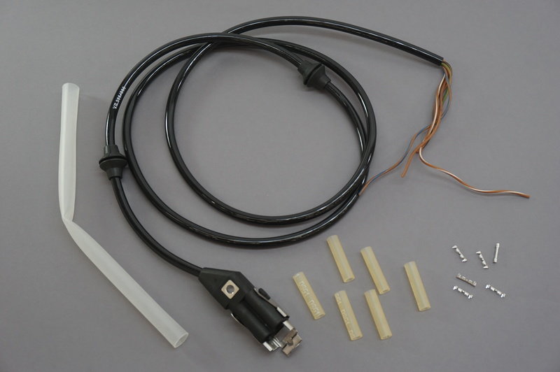
I did some digging and found an OEM ABS Wiring Harness Repair Kit (Part# 996-612-954-01-OEM) that should arrive tomorrow.
I can't seem to find much online re: installation instructions so I am guessing I'm going to need to break out a soldering iron, heat shrink wrap, etc.
Does anyone have any experience with this kit and have any installation advice to offer?
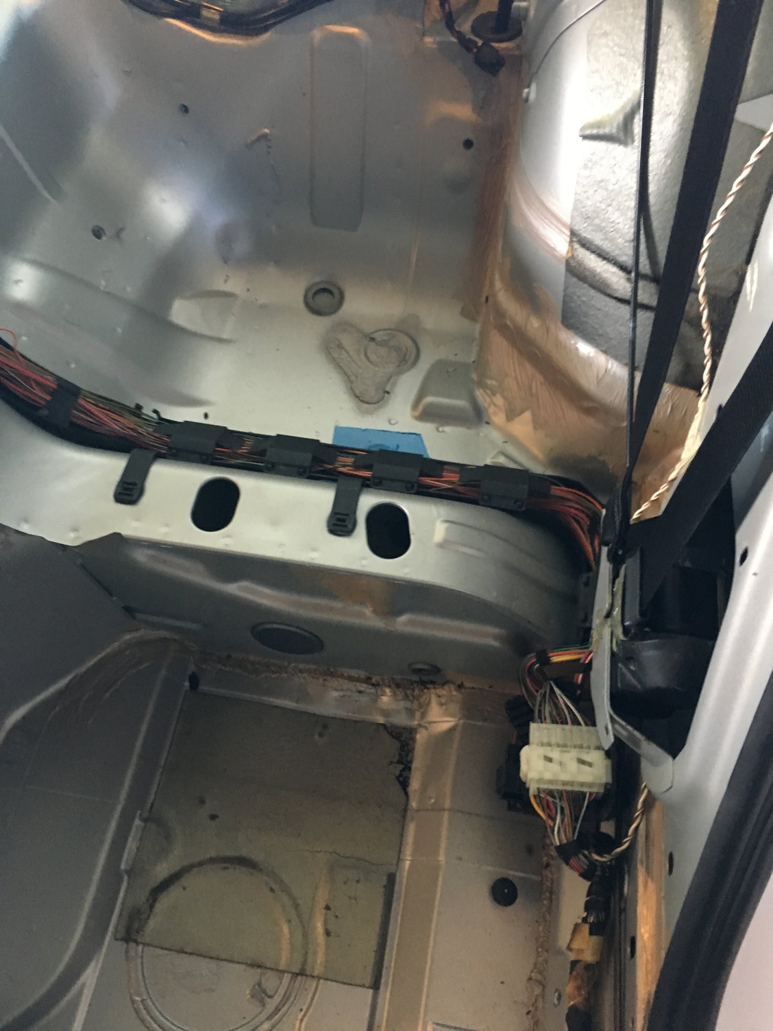
It has been a couple of years since I had the full interior out, but as I recall, the rear connectors require you to feed it up into the area under the seats. I think the larger of those grommets goest through the floor. You may end up with a pretty big project to remove trim, seats, carpets, etc.
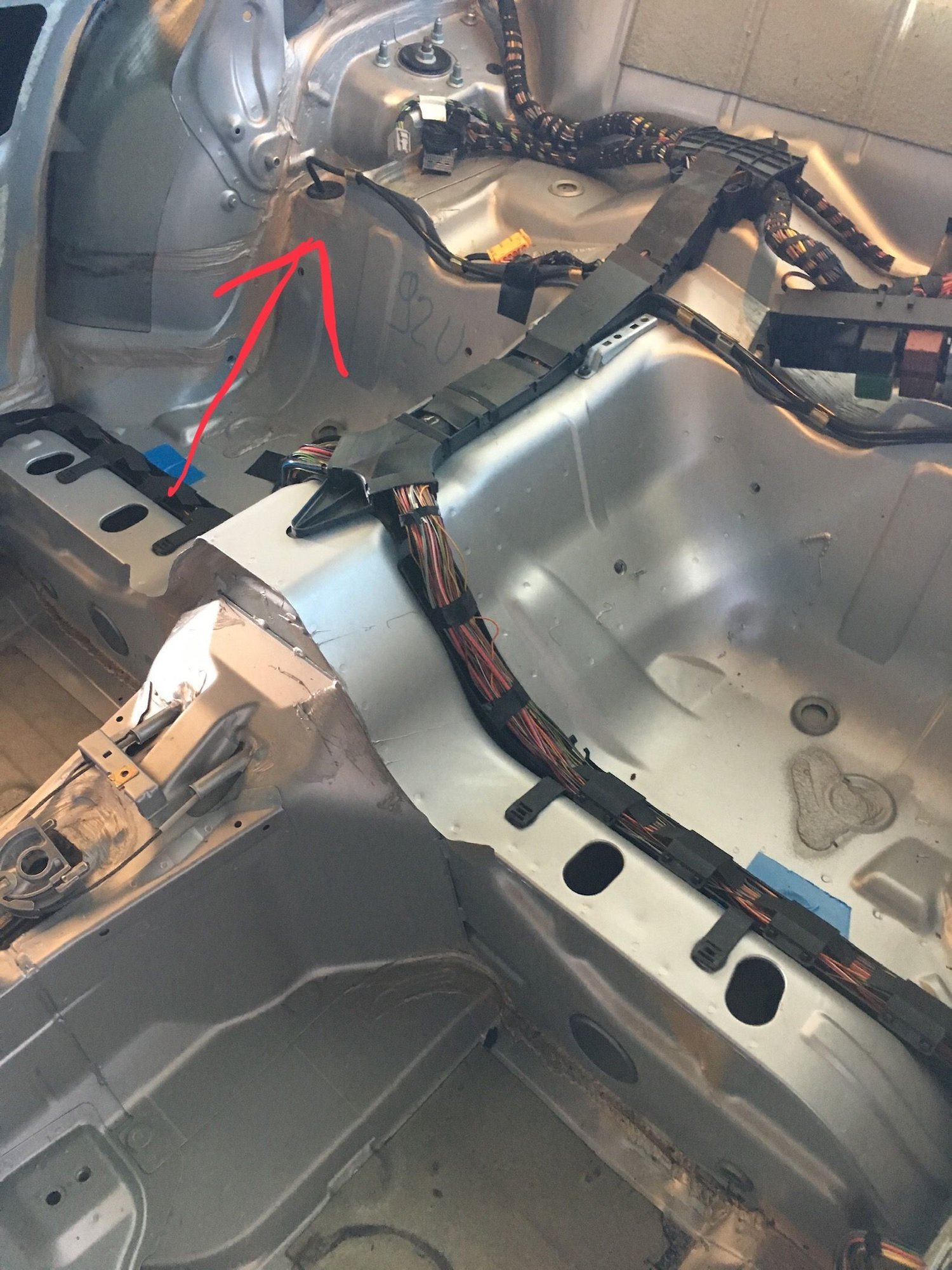
if you look in the uppermost right of this picture, I think that is where it pokes through. I had this all stripped out when I replaced my wiring harness.
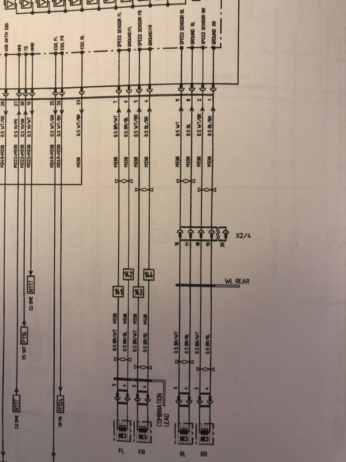
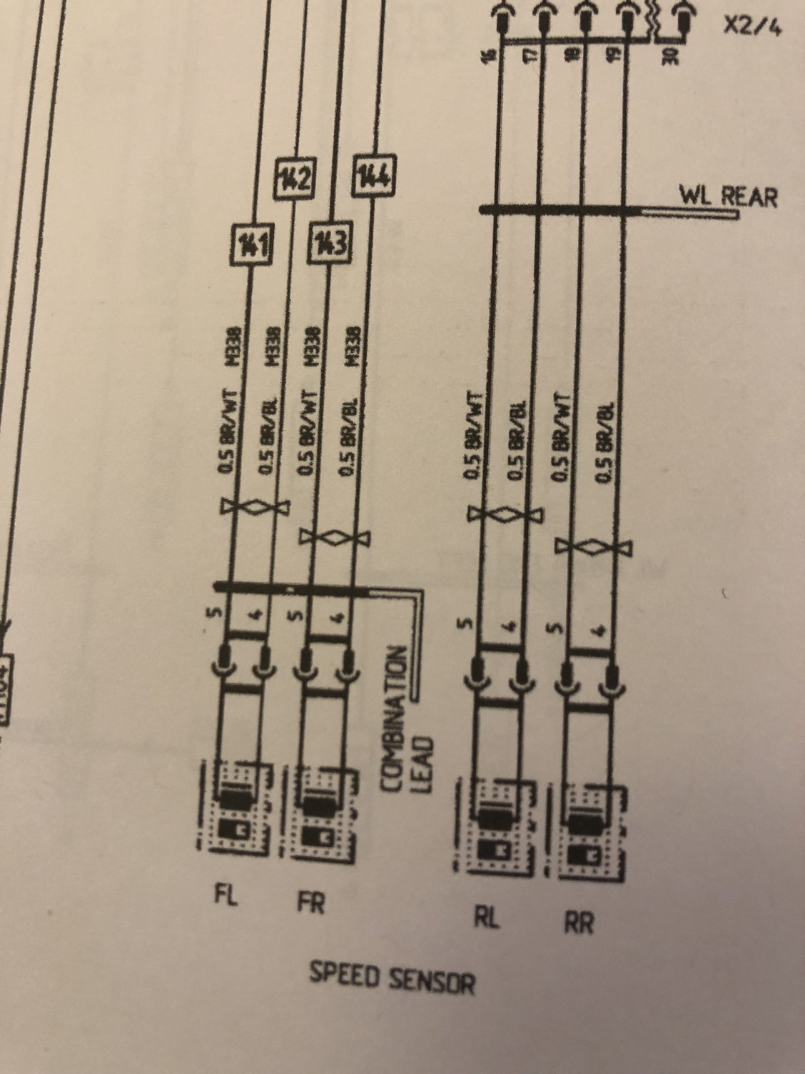
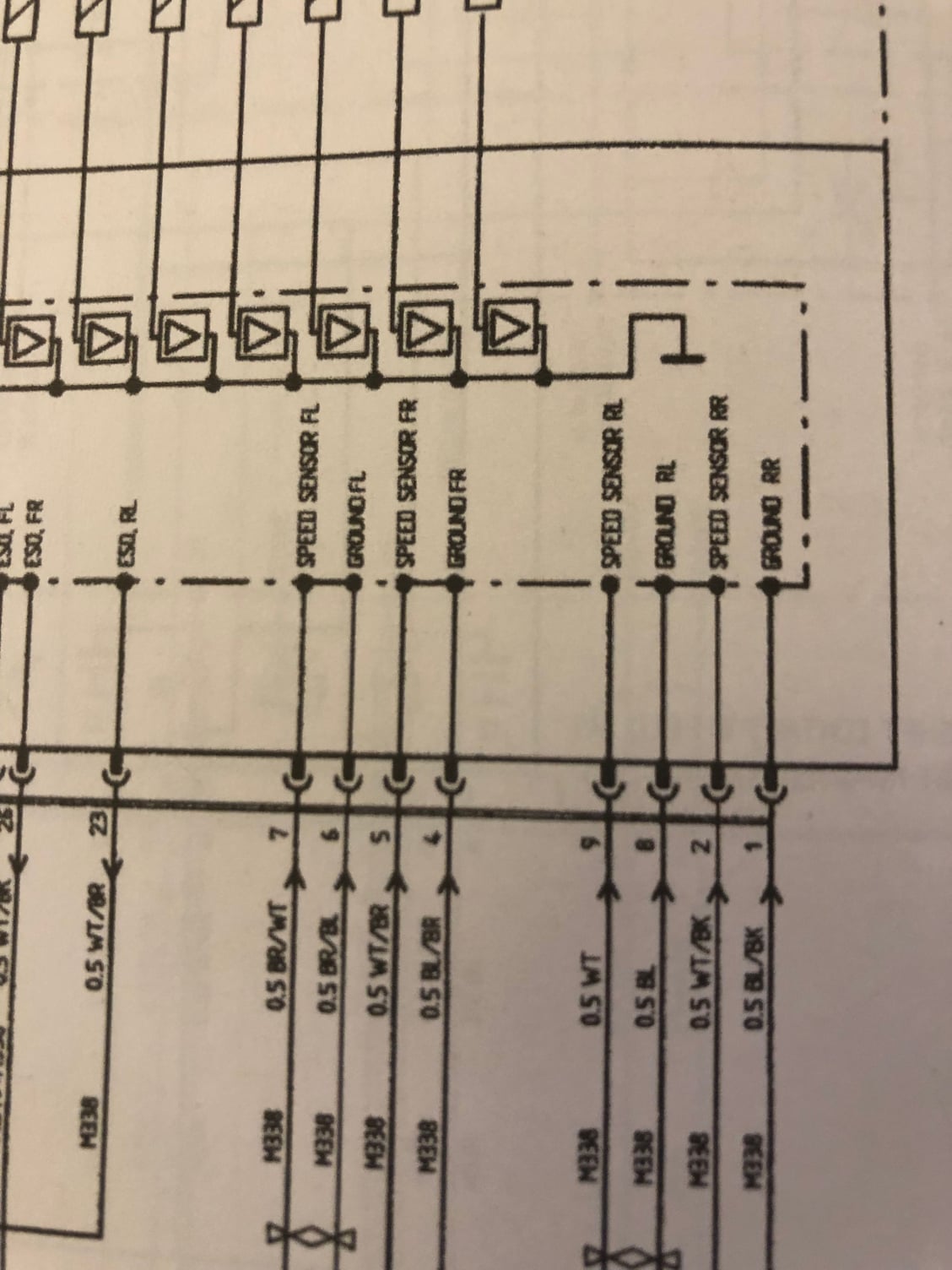
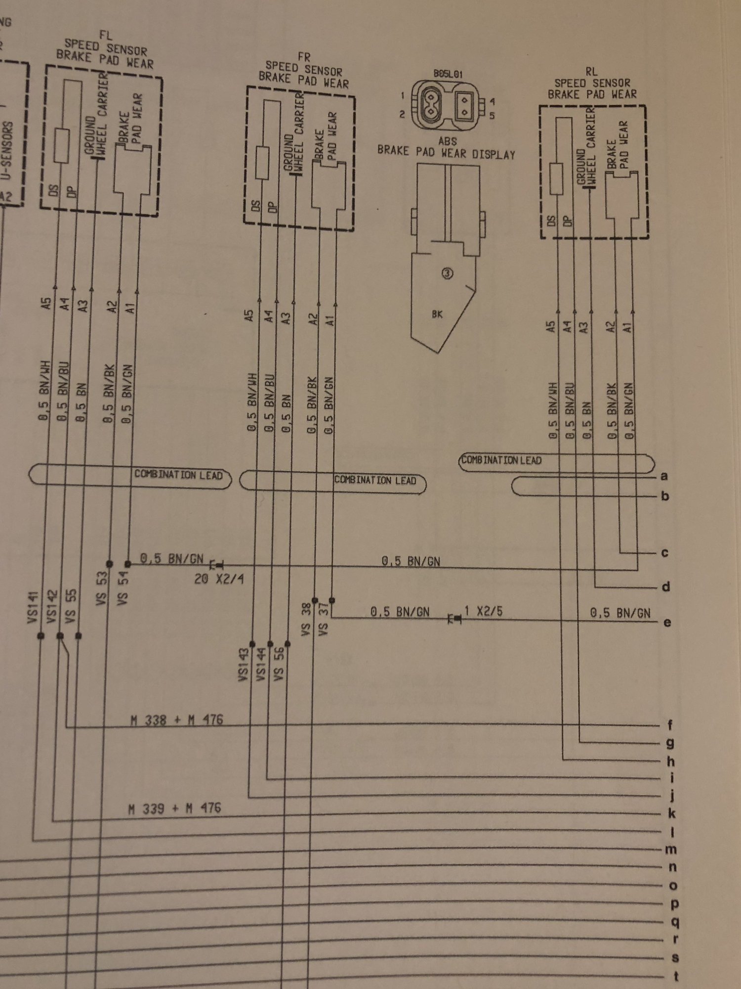
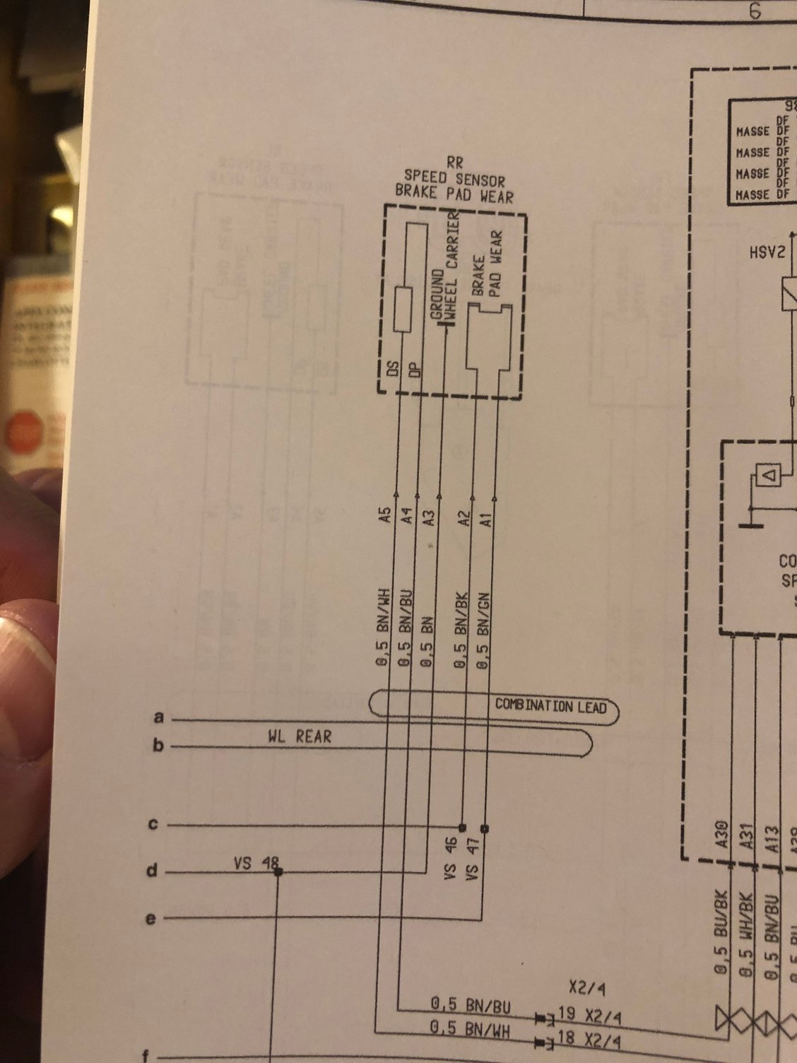
Not sure what year your are dealing with, but here is the relevant bit of the wiring diagram for a 99.
It has been a couple of years since I had the full interior out, but as I recall, the rear connectors require you to feed it up into the area under the seats. I think the larger of those grommets goest through the floor. You may end up with a pretty big project to remove trim, seats, carpets, etc.
if you look in the uppermost right of this picture, I think that is where it pokes through. I had this all stripped out when I replaced my wiring harness.
Not sure what year your are dealing with, but here is the relevant bit of the wiring diagram for a 99.
Thanks for the info!
By looking at the product pics, I was thinking it was a splice kit. Now it is looking like a multi-day process.
Does anyone with "rip the rear interior out" experience have any tips on what i'll need to take the back seats and carpeting out? I'd like to to purchase any tools I might be missing before I dive into the project this afternoon.
Relevant tools that I already own:
- Full socket/wrench set
- Plastic trim removal kit (I own two of these)
- Torx drivers/bits
- Triple square bits
- Allen bits
- Varior screwdrivers
- Misc auto-specific electrical connectors/fittings/fuses
- Electrical tools (Multimeter, dykes, pliers, strippers, crimpers, heat shrink wrap, heat gun, silicone bonding tape, electrical tape)
- RTV, silicone, dielectric grease
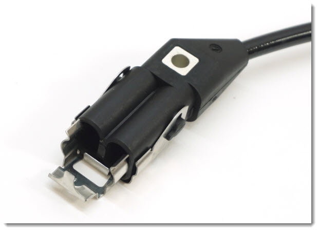
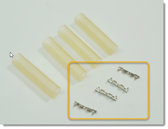
There is one connector type (included with the wiring harness repair kit I ordered) that I am unsure of. Is there a speciality tool to use with the following?
There are only a few fasteners (seatbelt, metal tray for relays, ground points, seat back latches).
Speaker grilles may be either Phillips or torx (I've seen both)
A bone tool (trim tool) is useful for reinstalling the side trim (rubber window gasket).
A lot of it is removing trim (w/plastic clips) and carpets.
You may need an allen wrench for the seat back bolts.
I seem to recall a triple square somewhere, but I don't remember where. Maybe the seat back bolts?
You've already heard feedback on a depinning tool, and the crimper was already called out. I have a radio shack crimper from forever ago that I use on pins like that. I use a heat gun for heat shrink.
Oh brother! I think you have your work cut out for you...
Just for grins I went and took a good look at where those wheel speed sensors terminate on my spare wiring harness (doesn't everybody have one, lol).
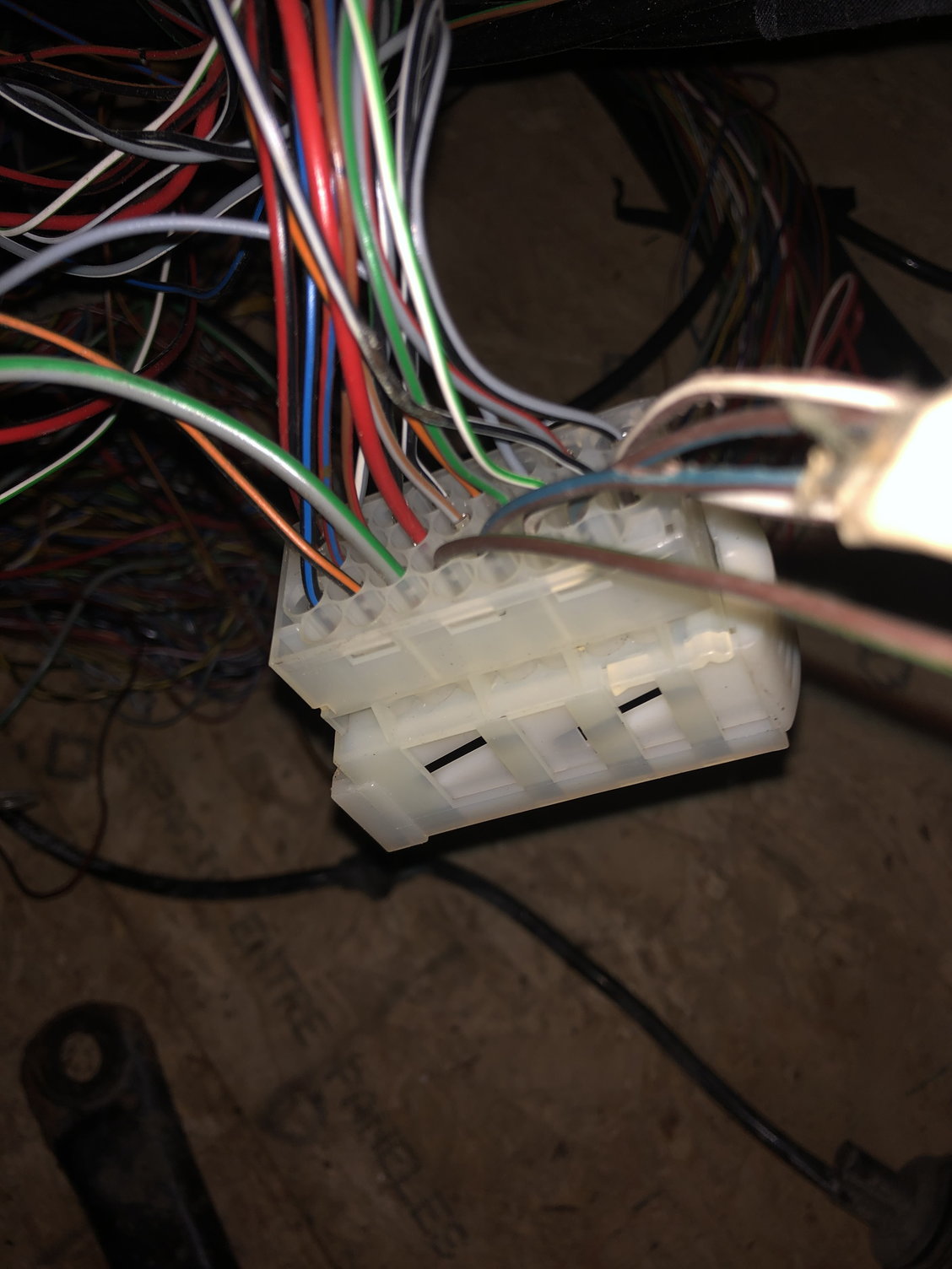
That harness goes from the wheel area, under the pan, up through the floor, across to the plastic loom cover over the transmission hump, then down to a white connector, which if memory serves is connected down at the side of the sill, near the bottom of the seatbelt area.
Where it comes through on the passenger side (mirror image driver side):
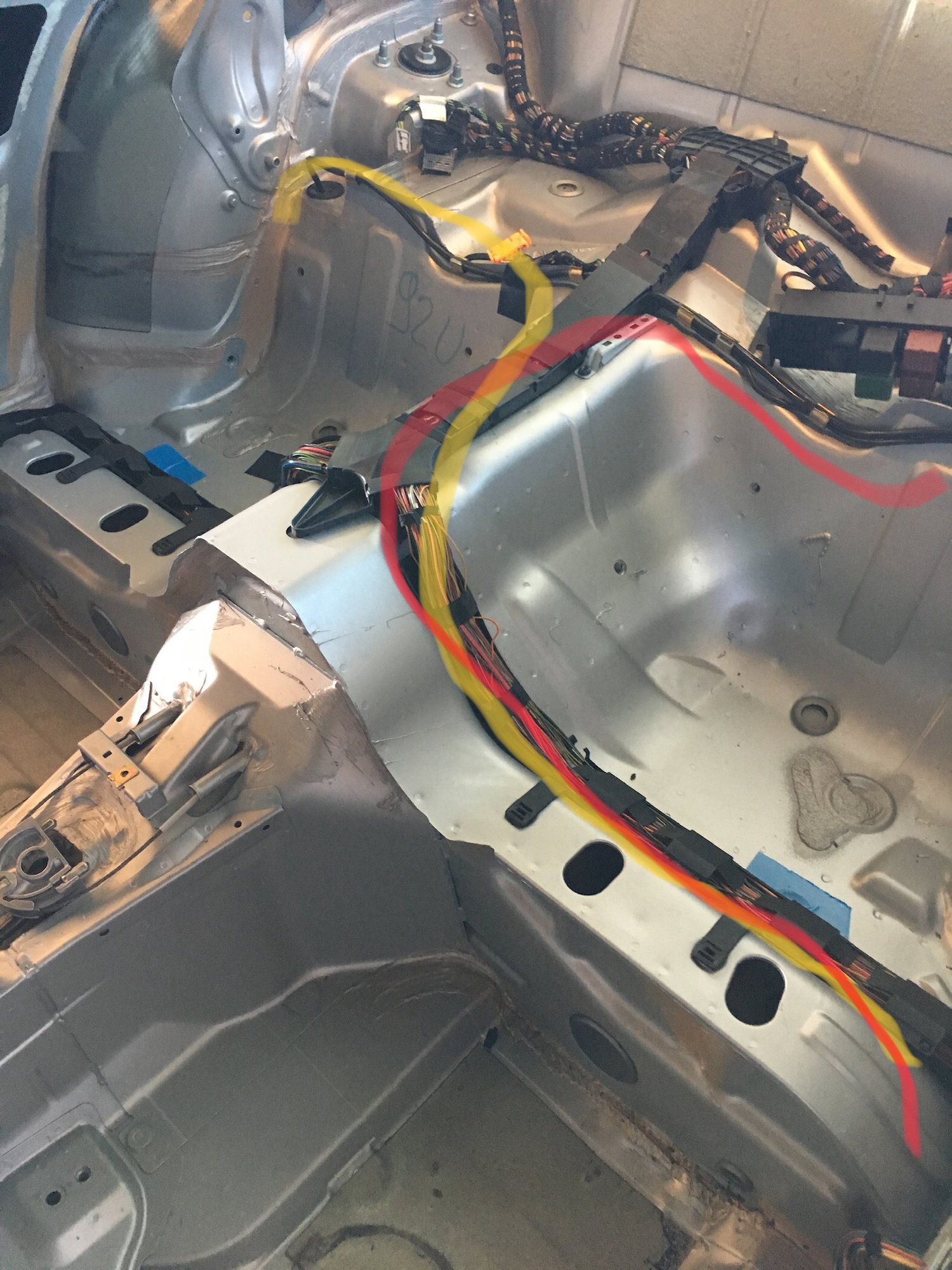
Path it follows on driver side (red) and passenger side (orange):
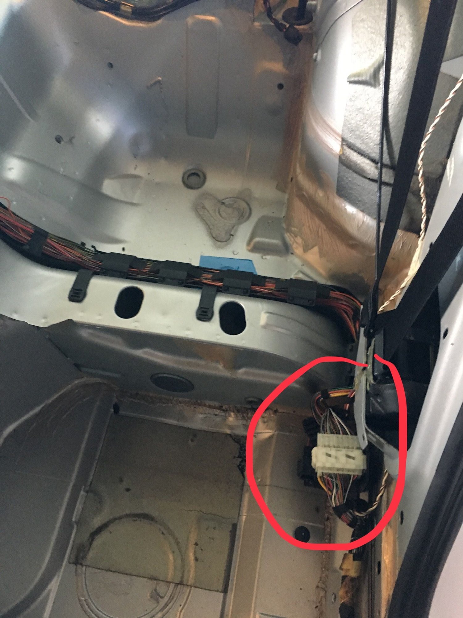
Please see the picture I posted above in post #2. The white connector is the one on the lower right of the picture.
If so, you're looking at front seats out too. Sill protector out. Main carpet out, or at least peeled back.
Here are some snapshots (sorry, not a good photo environment in the attic of my shop).
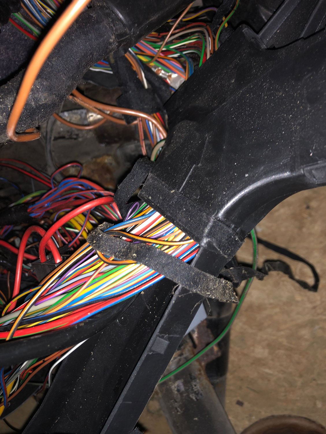
This is where the wheel speed sensor (shiny black larger sheathing at the left) harnesses enter the black plastic loom protector. Not a huge deal, but you'll have to get to it (remove carpet under rear seat) and open it up to surgically replace the sensor loom:
This is where the shiny black sheathing of that harness ends just prior to the wires going into the connector (next photo):
The two wheel speed sensor harnesses terminate in this white connector (I think these are the ones you'll depin and repin). The wheel speed sensor wires are the ones at the right in this photo:
I didn't trace the remaining wires to their termination, but they appear to do a 180 and loop back toward the plastic loom protector. If you need me to, I could chase them down.
So what is the argument against cutting the run about 6 inches outside of the wheel well and then splicing the wires (heat shrink wrapping the individual wires and then heat shrink wrapping the "bundle")? Would the splices induce any resistance to the circuit that could throw the ABS/brake pad wear indicators off?
Is this a viable solution other than not being "technically" correct?
If we analyze the product image and do some reverse engineering/sleuthing, couldn't it be inferred that Porsche wants the installer to cut and splice the cable run (vs. making your way all the way back to the white pin connector)?
My reasoning is as follows:
- The repair kit does not come with all wire ends terminated with a pin.
- The repair kit comes with crimp-type splice connectors.
- The repair kit comes with heat shrink tubing.
I have used this kit to repair all four corners of my �98 996. The heat here just kills those connectors! I went the splice method as I didn�t want to mess with re-pinning the connectors. The rear was a total PITA as you have to pull the carpet and rear seats. Pulling the front seats makes it easier but it is not mandatory.
 08-19-2019, 09:47 AM