When you click on links to various merchants on this site and make a purchase, this can result in this site earning a commission. Affiliate programs and affiliations include, but are not limited to, the eBay Partner Network.
Spoiler control in-dash Switch (& how to make custom switches)
Greetings,
I got my 996 in June and decided to do as much as I could do on it as a DIYer as it's really a geek car. I read a considerable amount of wonderful info here so I though I would share some of the work I've done on my car. Most of it has been done before, in different flavors, but he's my take on the spoiler in-dash control.
What I've done so far on my car since mid-june :
- garage door opener (in dash) mod
- moved HVAC controls down and freed a 2 DIN space to install a pioneer AVIC 910ZDAB with custom splash screen
- added USB extension for the head unit (android auto) and a 2 slot charging USB under the HVAC (I don't have heated seats, free space there, no switch)
- Removed the 6 CD charger in the trunk, freed the space to install a permanent trickle charger there
- Dimming footwell lights using the switched / dimming +12V from the dome panel and trunk/engine rectangular lights
- Replaced all filament bulbs by warm white LEDs (aliexpress)
- Added a backup camera + reverse gear activation (=> head unit)
- Change the turn signal light to 4 stalks. I don't have EGAS but I though maybe I'll find someone crazy enough to add the cruise control later. I wanted to wire the OBC (which was already activated)
- Removed instrument cluster, wired OBC control + spoiler position / activity wires
- Added the hand free microphone provided with the head unit in the instrument cluster stock position / grill
- Hacked a tiptro wheel to provide volume and seek control of the head unit
- Replaced the fuel tank cap and carrera logo with brushed alu model
Now to the topic : spoiler control. As pointed in several tutorial, you have essentially 2 or 3 options.
- use one of the 2 way switches with proper spoiler up/down logo on it (but no indicator)
- buy a custom indicator (or switch + indicator) from a german modder on ebay https://www.ebay.com/itm/Spoiler-swi...sid=m570.l1313
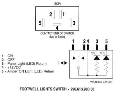
I mis ordered the indicator (solo, no switch) as I got confused by the pictures in the description. The indicator is a modded / drilled blank clip that is used to fill non used switch space on the dash. The electronic is simple but well designed and clever, the 2 information from the instrument cluster (spoiler up info + spoiler moving info via the motor relays return gnd) are merged together using a regular LED and a blinking LED, providing the proper truth table:
- relays enable the blinking LED circuit
- which is OR-ed with the spoiler up info (and it goes solid lit when up)
I didn't want to send it back to get a switch version, as it's much more expensive and I already had a footwell lighting switch which I decided to use. Also, while the electronics is nice on what I got, the blank cap is just covered with a white sticker : you can see the thickness of it, there's no backlight when you turn you headlights, etc, and I found this a bit lame.
The indicator part is sort of separated from the spoiler switch part, so it could be easier, but there are complications :
- Those switch with indicators are NOT wired with the same logic as the spoiler switche
- The lights have a common with the switch (while switches like the window switches have 2 pins dedicated to the backlight)
Those switches expect to be fed with positive logic, ie injecting +12V to the common, including the back light and the indicator. Closing the circuits returns to ground, for the switch or for the leds. The problem is that the spoiler control uses a negative logic to talk to the electronics : the common is a ground which pulls down some inputs to trigger either spoiler up or down. From the switch diagram above, we understand that feeding a ground on pin 4 will never get the indicators / leds on as they are wired in reverse.
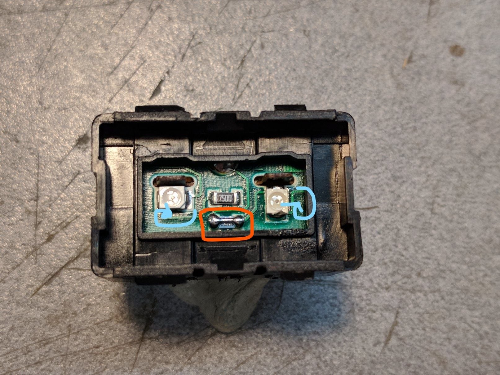
STEP 1 (BLUE): Reverse the LEDS.
The switch cover snaps off easily. Remove the anti dust tape, save it for later, it has enough tack to be put back in place afterwards
with a fine tip soldering iron, add a bit of solder on the leds tabs (to create heat mass when heated up) then heat both sides and flip the LED orientation / polarity.
STEP 2 (ORANGE) : bypass the current limiting resistor of the indicator (use a small piece of rigid wire, like a resistor leg). !t was needed in my case as the indicator electronics from the ebay seller is already coming with a resistor
STEP 3 : now your leds can be fed in positive logic, ie a positive voltage to light them up. I grabbed the brown wire from my indicator electronics and hooked it to pin 5 of the switch
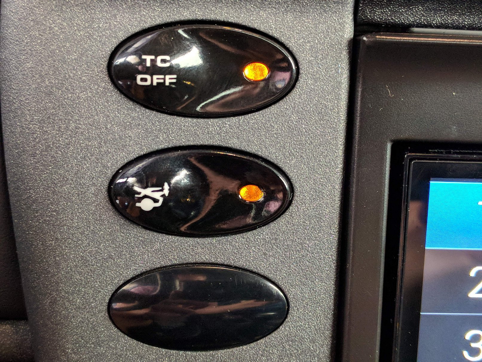
STEP 4 : back light. You CAN'T use the back light wire from a switch with indicator, as you just reverse the logic / polarity of your led. I had one of those just above my spoiler control selected location, the Traction Control switch. Below, luckily, I had the wiper speed ****, which is wired the right polarity, ie a positive voltage comes when you turn your head lights on. It was the grey/brown wire in my case (+ red dash). This goes to pin 3 of the switch
TO BE NOTED : the provided indicator electronics has actually 2 wires to the LED. The ground return goes thru the blinking LED (hidden in heatshrink) to provide blinking when the spoiler moves. As we use the spoiler control GND as a return, this has to go. Instead, with a brighter solid indicator when the spoiler moves, then it goes back to normally lit / solid once in position (and off when not extended). The bright side (pun intended) is that we get the backlight when you turn your lights on, and it looks great.
BUT WAIT.... you used a footwell light switch, it doesn't match the spoiler control logo, how LAME !
PART II : HOW TO to make custom switches / repurpose an existing switch
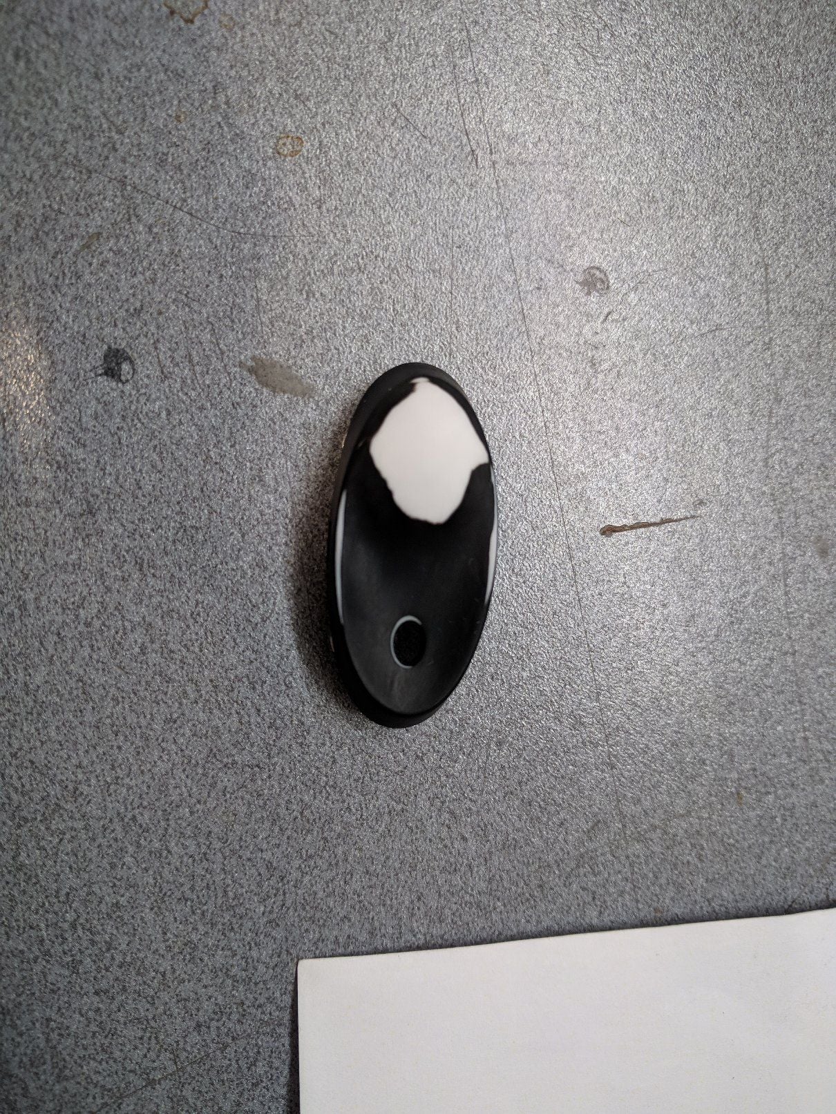
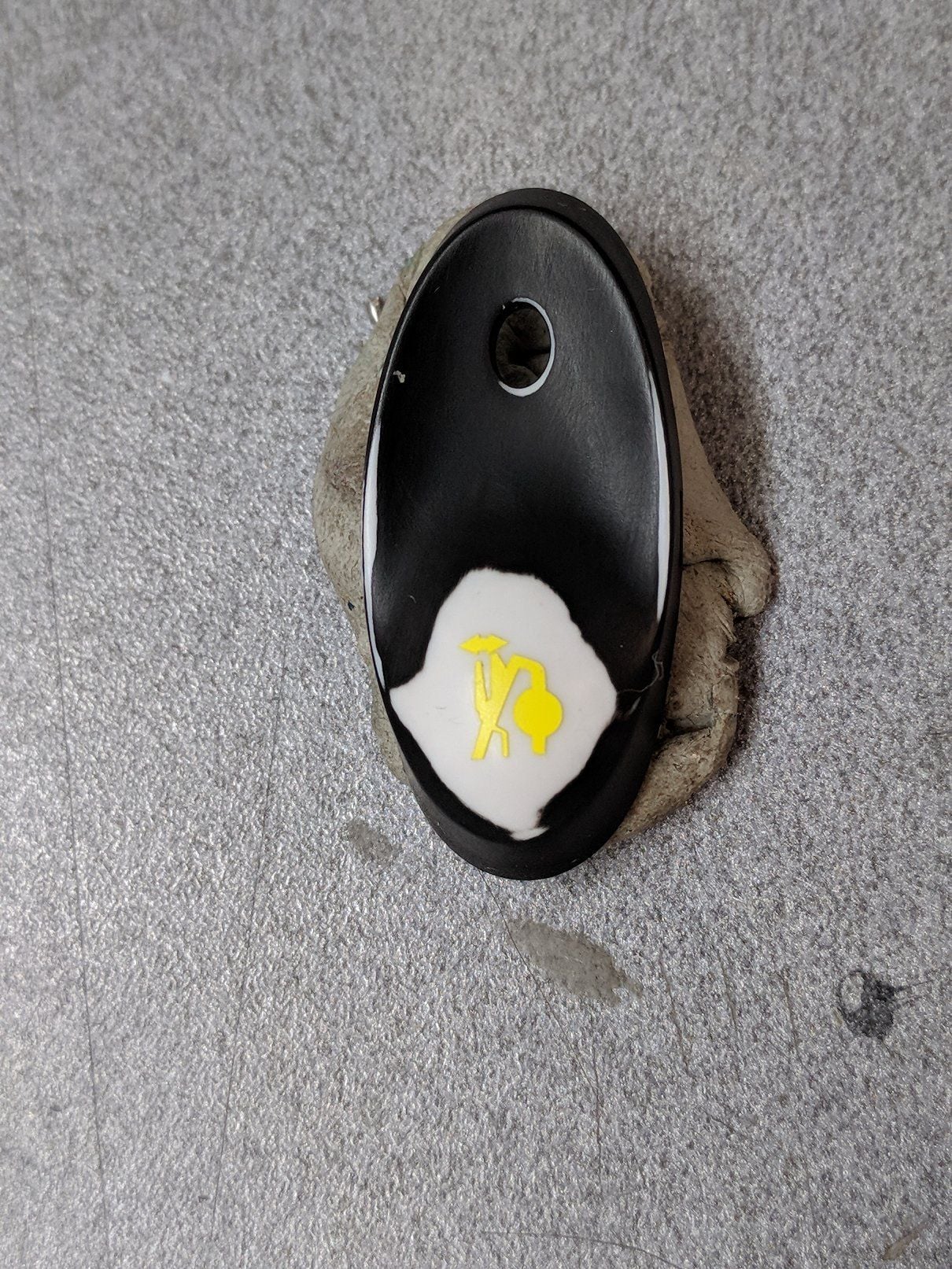
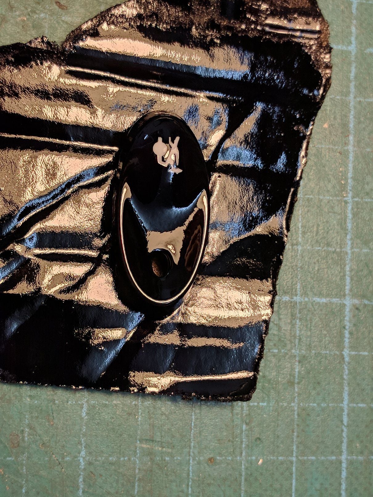
The switch cap is translucent white covered by black paint, except where you want the logo to appear (and the back light shine thru). I just wet sanded mine with 1200 grit automotive paper.
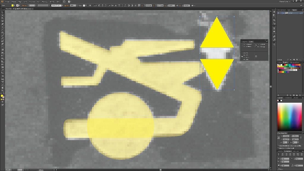
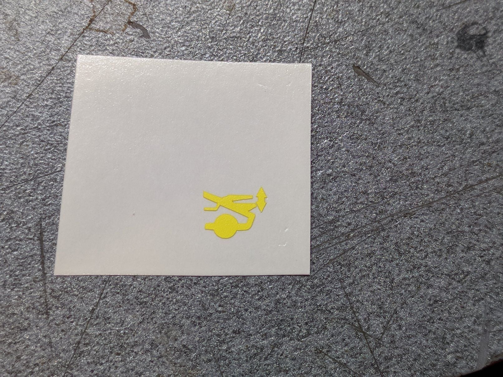
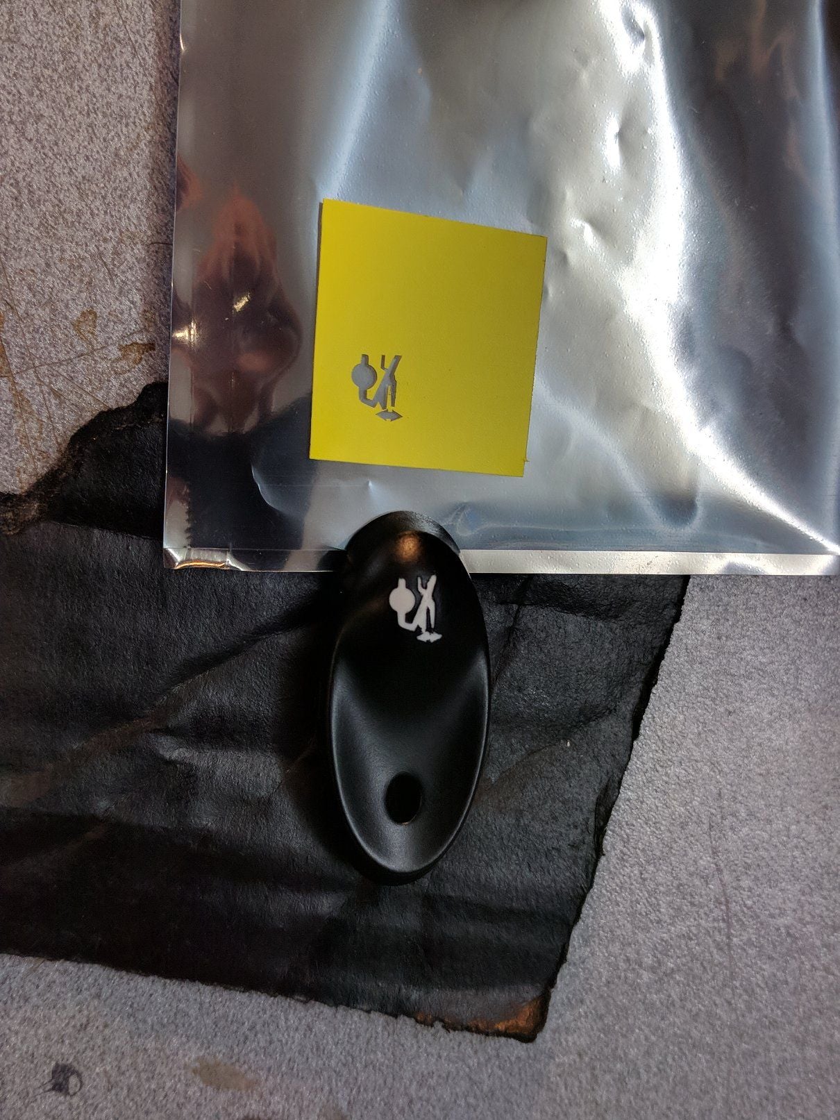
Then I created the spoiler logo using the small sticker I got with my kit, quick scan and Illustrator to the rescue
The I cut the shape with my vinyl cutter (cameo) and left over ritrama film. Carefully peeled off and placed with transfer tape (clear, to see where I place it)
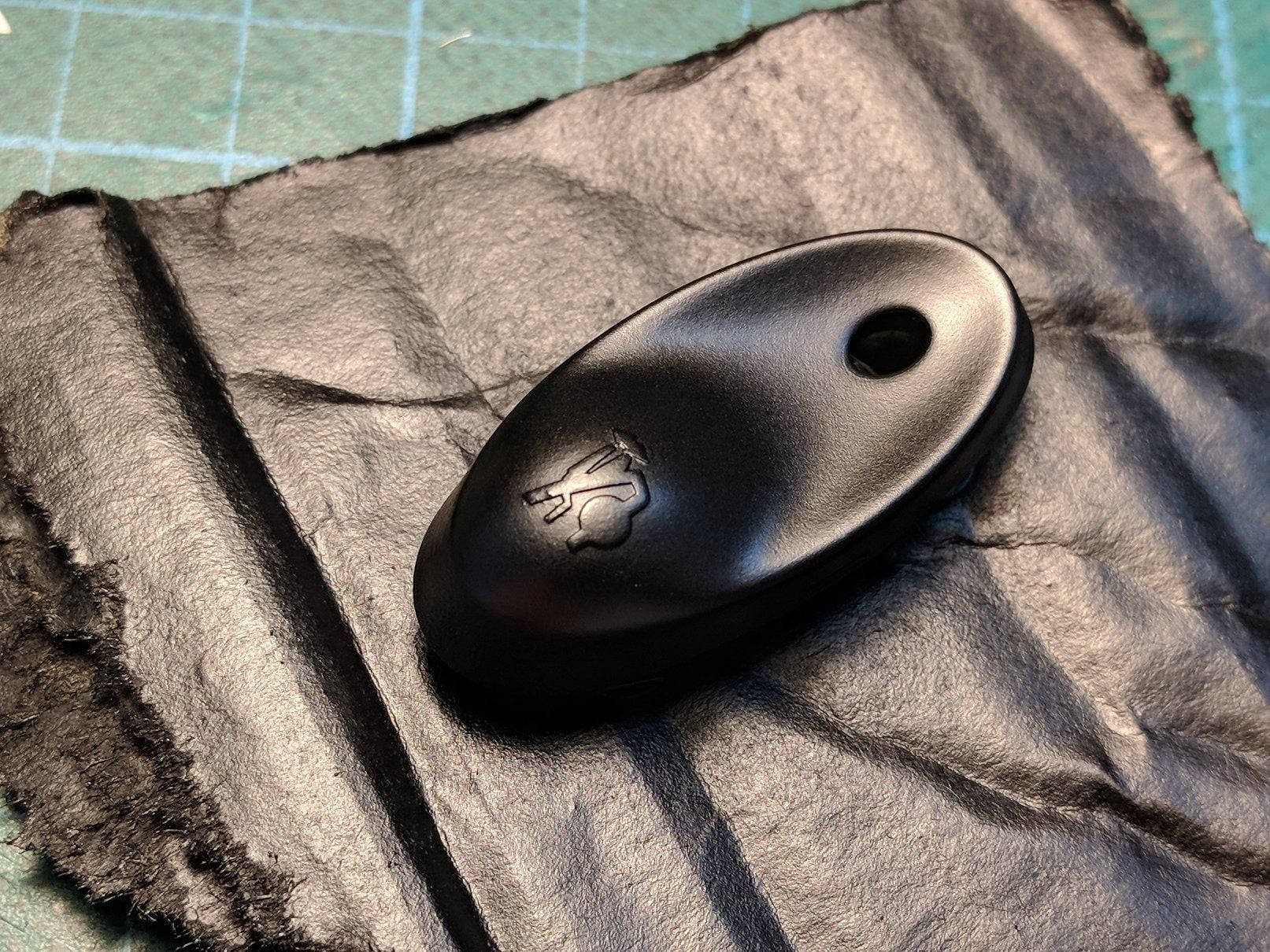
Then 2 coats of plastic paint (flat black)
And finally 2 coats of clear. ET VOILA (because I'm french after all)
final pics installed in the car tomorrow, it's still curing. Hopefully you'll enjoy that small tutorial. I will share my tiptronic wheel retrofit (head unit remote control) work in another post.
not exactly, that switch above is the "regular" hack but lack of an indicator which was the plus of the german kit (ebay). I do have a small aerokit on my spoiler so I can see if it's up or down, but many people don't, so knowing the state of the spoiler was important, hence this variant of the hack.
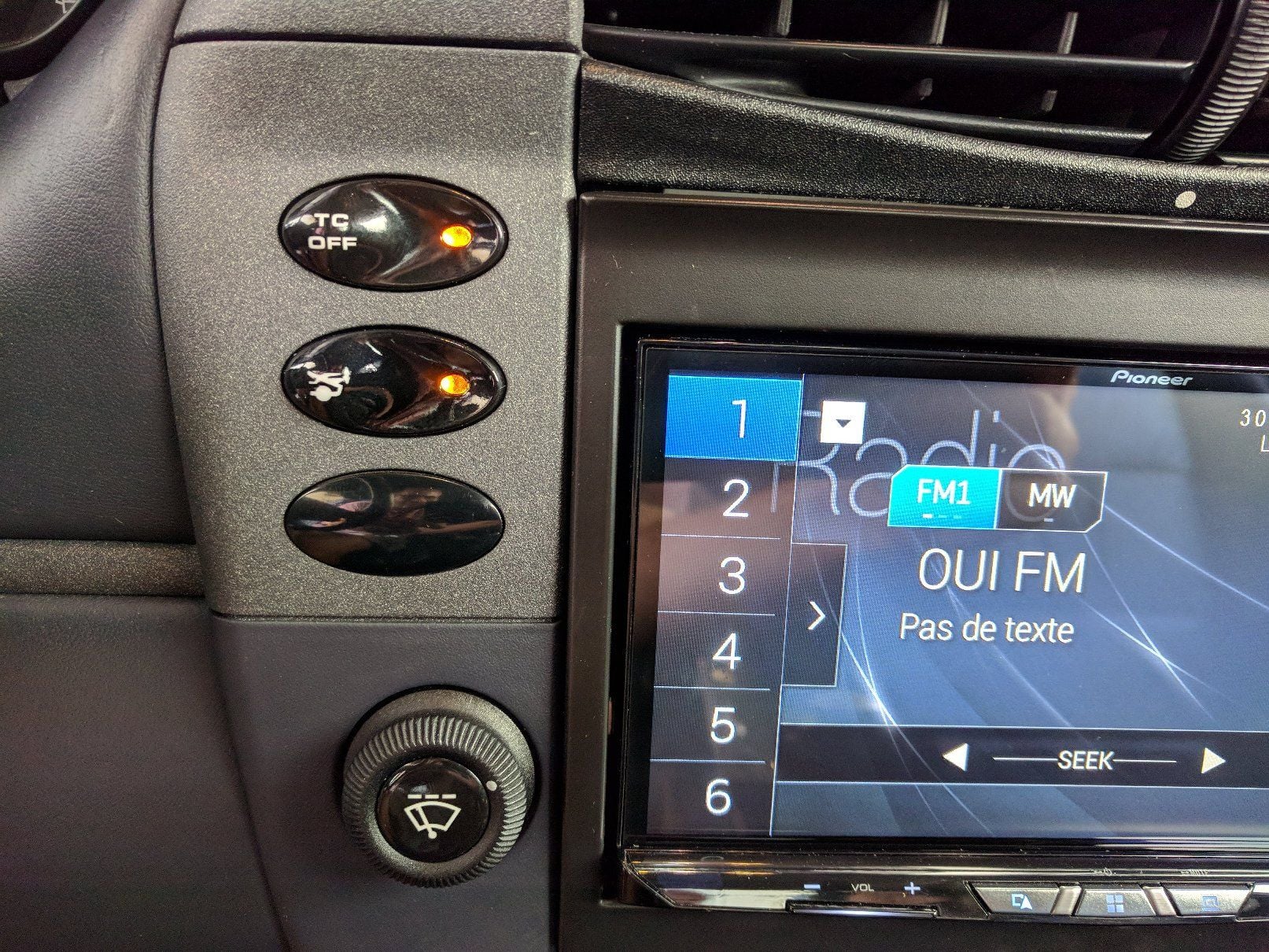
Here's the final result once installed. It really looks legit to me :-)
 07-29-2018, 04:16 PM