When you click on links to various merchants on this site and make a purchase, this can result in this site earning a commission. Affiliate programs and affiliations include, but are not limited to, the eBay Partner Network.
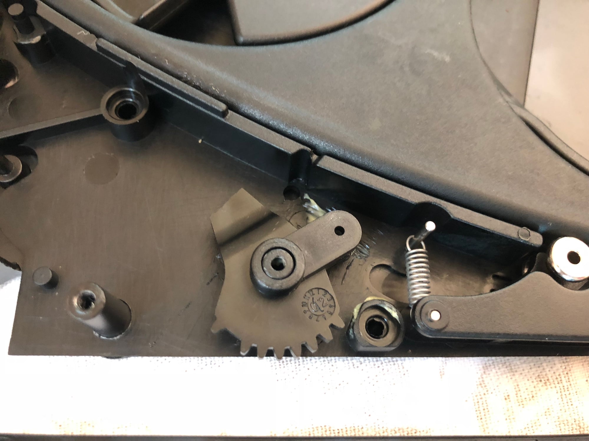
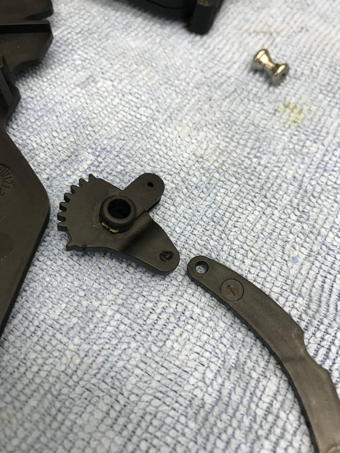
The arm coming off the plastic gear that slides the cup holder's face to the side when opening/closing broke. I decided to take it apart to see if it would be possible to 3d print a replacement, rather than purchasing a new cup holder. Unfortunately, the other half of the part is missing (my hope was that it would be connected to whatever actuates it). So - I'm going to take a long shot and see if anyone here happens to have a picture of what this piece looks like whole, and what it connects to. Even a rough description would help me out considerably.
Thanks in advance!
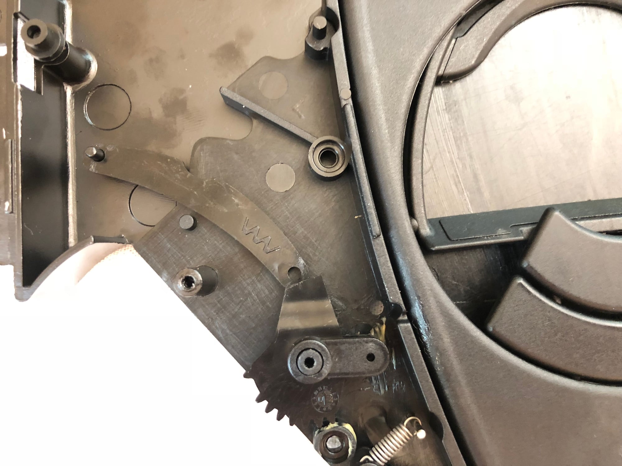
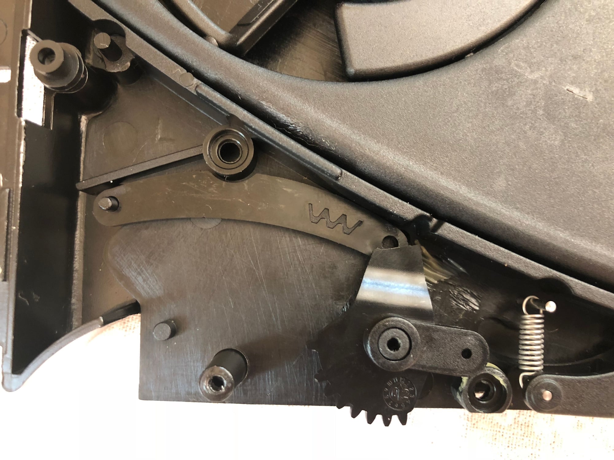
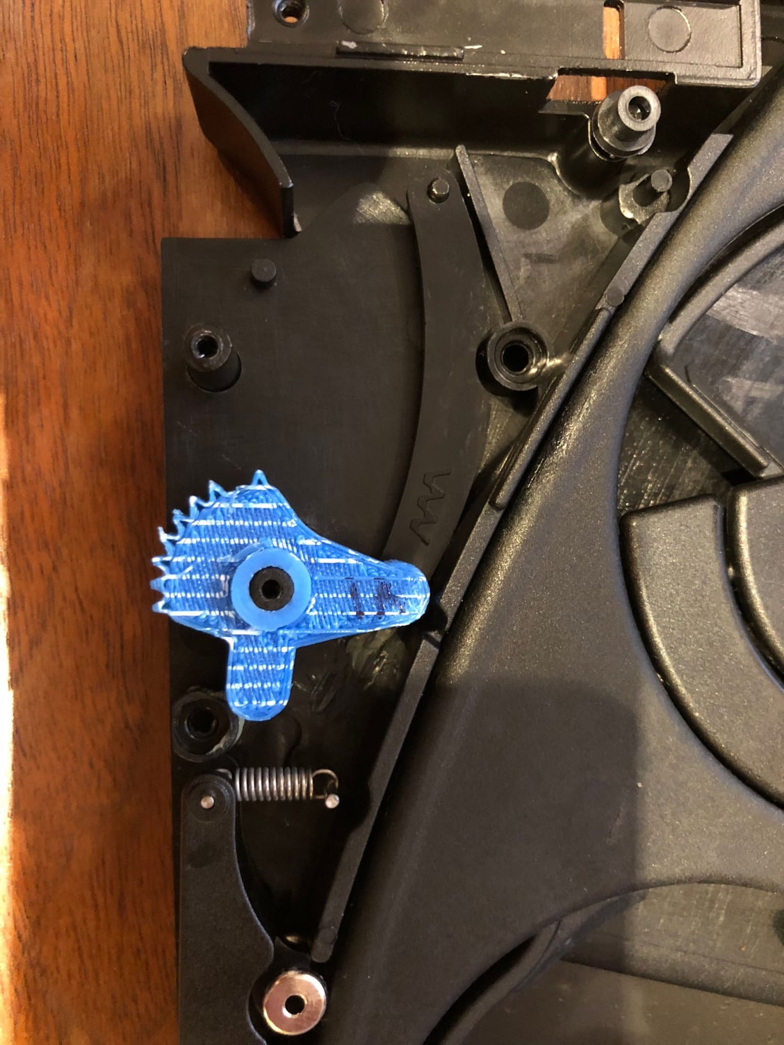
Here is the part in question, followed by a full shot of it in place:
I have the same problem, I haven't taken mine apart to see what the issue is. if I have the same problem and still have the broken parts in the mechanism I'll happily mail them to you and hopefully if you can print a replacement part I'd like to purchase one. As you I looked and they are pretty expensive to replace even with used parts.
I haven't looked into it but are they relatively simple to remove?
I'd definitely be up for making you a replacement if you can send me the entire piece (even if its broken) to measure. I can't say for certain if A) I'll be able to accurately model it (I'm pretty confident I can though) or B) the materials available for 3d printing will be strong enough to hold up to the abuse the piece takes. But, I'm willing to give it a shot.
That being said, getting the cup holder out isn't the hardest thing to do - but its not the easiest either. You have to remove the horseshoe trim piece (there are 4 retaining spots - 2 on each side) - you basically have to pry it off using a trim removal tool. I found this to be almost impossible to do without scuffing the plastic surface. I used painters tape on the dash around it, and that protected the dash - but I got a scuff on the 'soft touch' of the trim. I then disconnected the switches to get it out of the way.
Once the horseshoe is off, you have to remove the center air vents - this was actually not too hard. There are two tabs, one directly centered above each vent. Using a plastic trim removal tool you can slide it between the dash and the vent and see them, then depress them and pull the vents straight towards you.
Next you need to remove the frame that everything was mounted to (including the stereo). There are 4 screws holding it in place. The cup holder comes out on the frame and there are two tabs holding it in place. It slides out the back when the tabs are depressed.
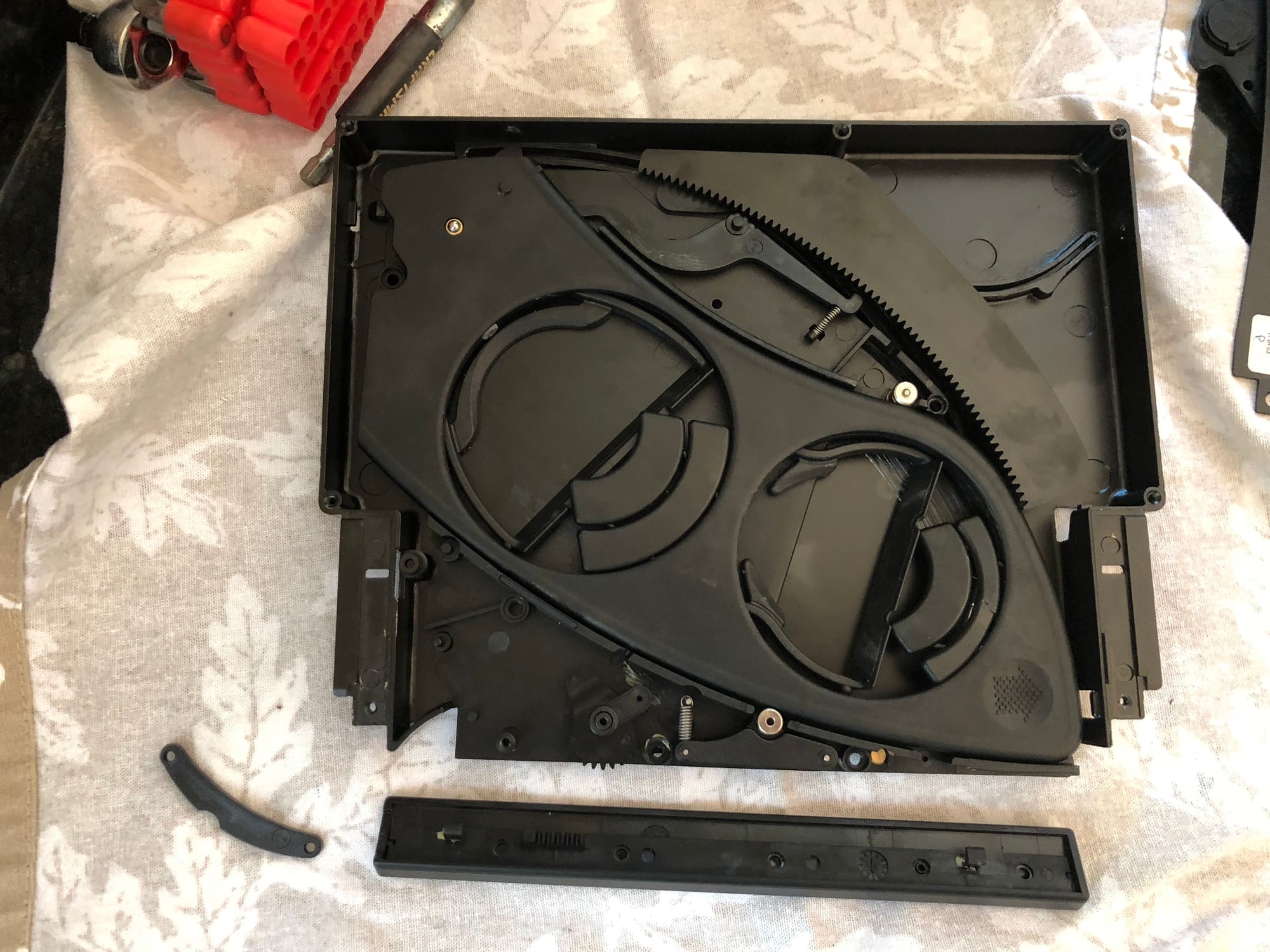
Actually taking the cup holder apart is pretty straight forward, but go slow and take lots of pictures. This thing is ridiculously over engineered. There are no less than 10 springs, along with ball bearings, and a ton of other pieces. I may count up all the pieces just for fun.
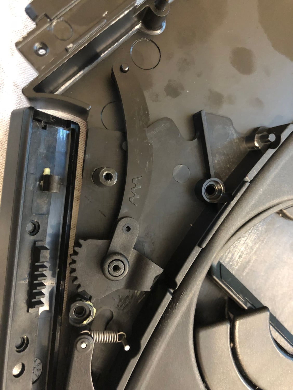
I've been scratching my head on this one trying to understand what is missing and how it fit together. Here are pictures of it assembled the only way that I've been able to come up with - but I suspect the broken gear piece of upside down as it doesn't mesh up with the sliding faceplate properly. Other than that, it makes perfect sense. So, I don't think I've actually made any progress yet.
Thanks for posting Gunar - your second set of pictures confirmed my suspicion about the gear orientation.
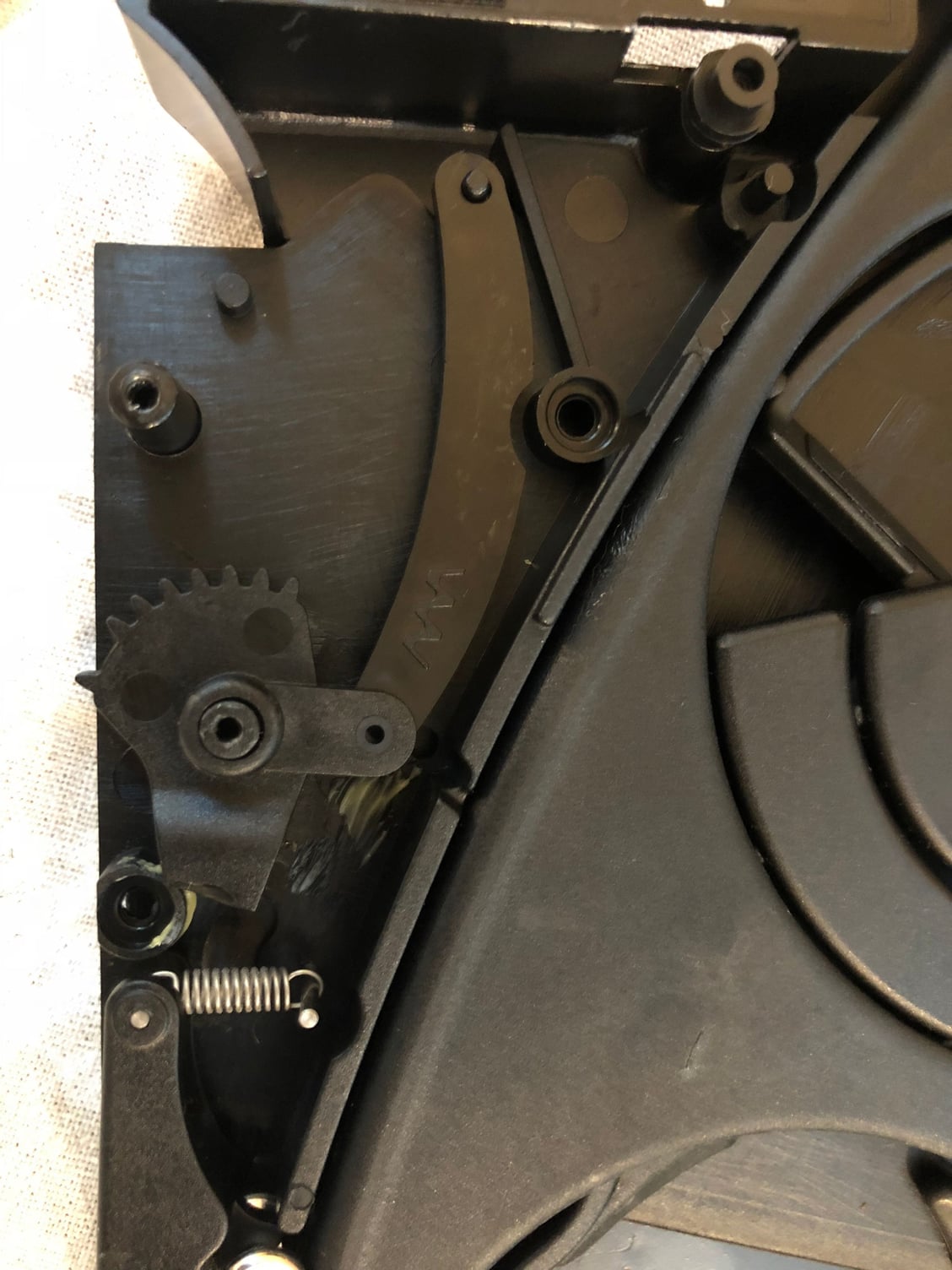
Based on that, this is my latest attempt at figuring out the configuration. I'm a bit concerned with the clearances in the 'closed' position - but other than that everything looks like it could possibly work. At this point I'm going to start working on a prototype part to test it out. If anyone has assembled this and remembers how these parts went together, and can let me know if I'm on the right track I would appreciate it!
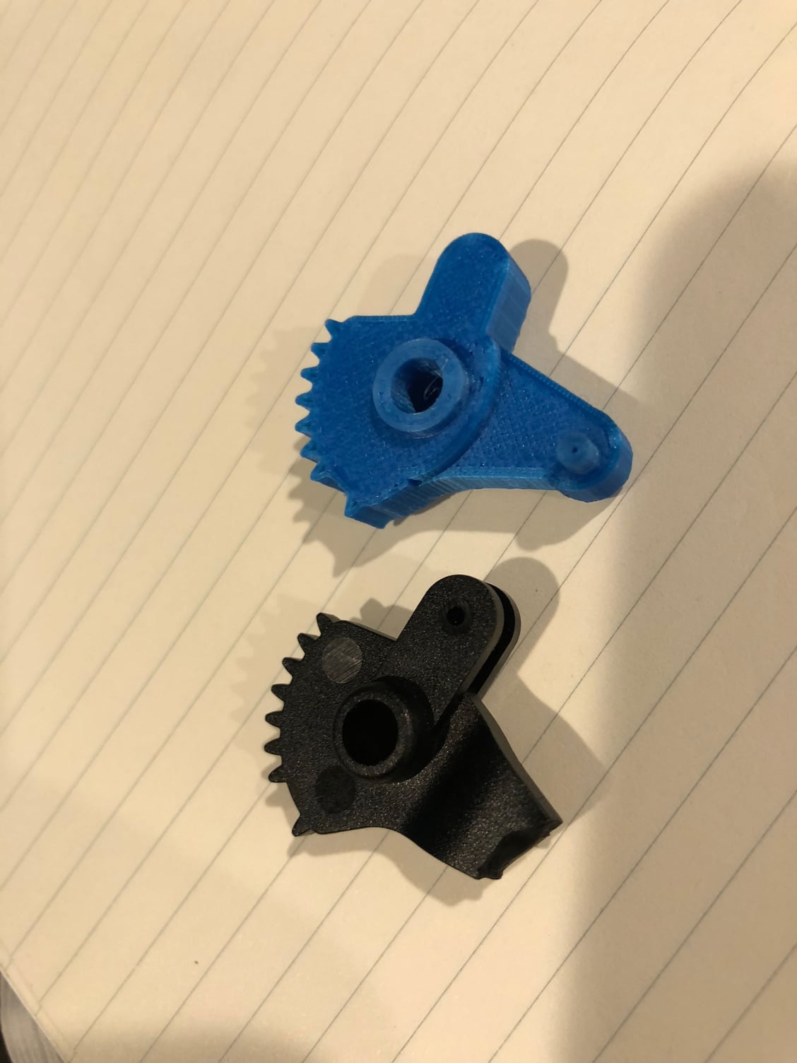
I did my best to workout what was missing from my gear, and then took a stab at re-creating the part - and the missing section, in Fusion 360. Printed version 1 and was stoked to find that not only did it fit (nearly perfectly) but it actually worked exactly like it should. I also thickened up the design (especially in the area where the original broke) because there are no clearance issues requiring it to be that thin. So, I'm pretty thrilled, because this was the project I used to justify the purchase of the 3d printer to my wife - and up until now I wasn't convinced it would be possible to accurately model this part and print a replica that functions. It turns out, it is possible and it wasn't as difficult as I expected.
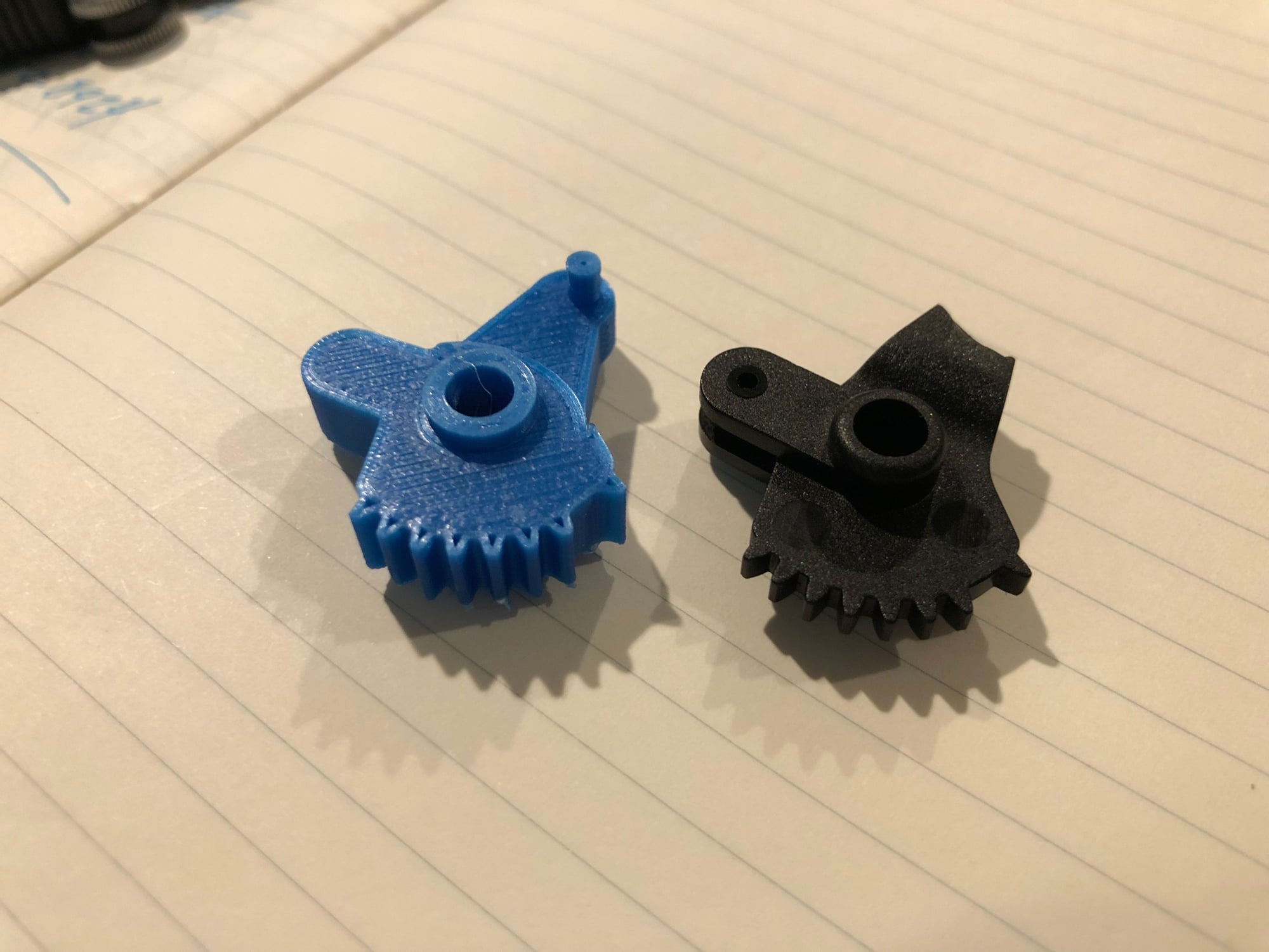
Below are pics of the pieces side by side, as well as what it looks like in place (both open and closed). I'm going to tweak a couple little things, and also try to get the teeth to infill solid - although I think they're plenty strong as is. This prototype was printed in PLA, which has a lower melting point and may not fair well in a hot car during the summer, so once I get the tweaks finished and verify success I'm going to print one in PETG.
One of the little flaps that push down when you put a cup into the cup holder is cracked, so next up is to print a replacement one of those as well. When I'm finished up, I'm going to make a quick tutorial about how to remove the cup holder, and how to disassemble it and put it back together.
So the pin on my gear broke, a little different to yours.
I�m going to try and epoxy in a small rod to fix it.
Anyone know what the other tab on the gear is for? I don�t think it�s used for anything, so what�s it there for?
Thanks for posting. This is the first pic I�ve seen of that part in its entirety. It�s nice to confirm that I got it right. I have no idea what the other side is for. It�s almost like a pin was supposed to go in there and have a spring hooked to it but I see no real reason for it. It kind of acts as a stop/bumper to prevent the mechanism from turning past its end point.
Epoxy and a metal rod or screw seem like a good solution. If you�re interested in a 3D printed replacement send me a PM. Im going to put mine back together next week and so some real world stress testing to confirm it holds up - but I expect it to.
 07-09-2018, 12:04 PM