When you click on links to various merchants on this site and make a purchase, this can result in this site earning a commission. Affiliate programs and affiliations include, but are not limited to, the eBay Partner Network.
I'm not forgetting anything but I have failed to explain it clearly.
You can do a very simple test. Read the oil temp using Durametric (with the gauge disconnected) then quickly connect the gauge and check Durametric reading again. It should read LOWER oil temp now.
.I did do a test with a DVOM connected to the DME signal wire, With the key on cold engine the DVOM was reading 2.5xx volts, then connecting and disconnecting the gauge had no effect in the voltage, so I assume it has no effect on the DME since this is exactly what the DME sees. I will do it with Durametric just to confirm.
.I did do a test with a DVOM connected to the DME signal wire, With the key on cold engine the DVOM was reading 2.5xx volts, then connecting and disconnecting the gauge had no effect in the voltage, so I assume it has no effect on the DME since this is exactly what the DME sees. I will do it with Durametric just to confirm.
If the voltage is the same, Durametric will return the same reading so probably no need to recheck using Durametric. Um, I don't really understand the circuit then. Was the gauge powered when you did the above measurement?
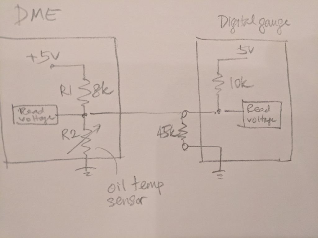
The reason I said the 8k is parallel with the 10k is because each is connected to a separate 5v power. The circuit will then be equivalent to both resistors connected together to a SINGLE 5v source so they are essentially in parallel. Is the circuit something like below?
If the voltage is the same, Durametric will return the same reading so probably no need to recheck using Durametric. Um, I don't really understand the circuit then. Was the gauge powered when you did the above measurement?
The reason I said the 8k is parallel with the 10k is because each is connected to a separate 5v power. The circuit will then be equivalent to both resistors connected together to a SINGLE 5v source so they are essentially in parallel. Is the circuit something like below?
Yes, this is the basic layout of the circuit, with all the other electronics behind that..lol. What are you thinking? And yes the Gauge was powered on when checked.
I cannot explain it then. Based on the above, the voltage reading should be different with and without the gauge connected (higher when gauge is connected). The reason is very simple. V = IR, the voltage measured = (current thru R2) x R2
Without the gauge, there is only one current path, from the DME 5v thru the 8k resistor. With the gauge connected, there is an additional current path from the digital meter 5v feeding through the 10k resistor so the current through R2 will become HIGHER so the voltage measured should also be higher.
I think the explanation is that the R2( Factory NTC) will allow more current to flow, without a change in voltage, but will change voltage as per temperature regardless of current.
Last edited by Porschetech3; 01-10-2018 at 03:14 AM.
I think the explanation is that the R2( Factory NTC) will allow more current to flow, without a change in voltage, but will change voltage as per temperature regardless of current.
The factory sensor is just an ntc type thermistor (basically temperature sensitive resistor) so it has to follow ohm's law V= I x R. For a given R, when the current increases, the voltage will also increase.
The factory sensor is just an ntc type thermistor (basically temperature sensitive resistor) so it has to follow ohm's law V= I x R. For a given R, when the current increases, the voltage will also increase.
Yes I agree with all above, but in this instance all 3 V I R are all moving targets. On your example : For a given R, when the current increases, the voltage will also increase. is true, but how do you increase the current? You can't if you have a fixed R and a regulated V.
Edit: The current through R2 will not be HIGHER, it will be LOWER, adding resisters in any circuit whether parallel or in series will LOWER current and or voltage.
From what I see in the circuit, we have a moving voltage , a moving current, and a moving resistance (with temperature)
Go back and read my water hose analogy, but instead of useing a garden sprayer at the end of the hoses, use a pressure regulating devise that regulates pressure as per temperature, regardless of flow.
I respect your computer/electronics savvy and want you to agree with me, I am beginning to doubt myself even though I have done tests and thought this out, my head is starting to spin thinking through moving scenarios. lol
Last edited by Porschetech3; 01-10-2018 at 03:15 AM.
Thanks for entertaining my thoughts. Keep in mind the stock oil temp sensor spec is a graph of temperature vs resistance so the sensor is just a passive resistor and it does not regulate voltage. It's strictly a passive component.
*IF* the circuit is truly like the above, I guarantee the voltage measured will be different if the gauge is connected for a given temp (R2).
Btw, even the 45k resistor will lower the sensor resistance because it's connected parallel to the sensor. So it should also affect the voltage measured.
Thanks for entertaining my thoughts. Keep in mind the stock oil temp sensor spec is a graph of temperature vs resistance so the sensor is just a passive resistor and it does not regulate voltage. It's strictly a passive component.
Well I guess we will have to disagree for now. I understand how a thermistor works. In this instance it does it does not regulate voltage . but can change voltage per temperature, as is not effected by current change(because the current change is always lower ie more resistance)
Originally Posted by Ahsia
*IF* the circuit is truly like the above, I guarantee the voltage measured will be different if the gauge is connected for a given temp (R2).
The circuit is like above, I had edited by previous post and you may not have seen it, but adding resistors in parallel increases current, (but not through the NTC rather through the internal resistor and is not measured)) but in series reduces current/
Originally Posted by Ahsia
Btw, even the 45k resistor will lower the sensor resistance because it's connected parallel to the sensor. So it should also affect the voltage measured.
The 45k resistor increases the total resistance the Digital meter sees (10k and 45k in parrellel=8.1k) plus NTC 16k at 25C.....but the meter takes it reading between the 10k and 45k resistors and it DOES affect its voltage reading on purpose to have a similar voltage drop as the meter expects a NTC resistance of 10k at 25C (B3950) but gets a resistance of 16k at 25C.
The DME sees a total resistance of 8k plus 16k (NTC) at 25C but takes its reading between the 10k and 16k resistors. The 45k resistor that is on the other circuit merely causes a little more current to flow through the 8k internal resistor.(with no change in voltage)
Last edited by Porschetech3; 01-10-2018 at 05:17 AM.
OKAY !!! I have figured out the reason I have been having a hard time explaing WHY my simple circuit works, and HOW it works. Think of it in terms of ELECTRON FLOW ( instead of CONVENTIONAL CURRENT which is incorrect)
The electrons actually flow from negative to positive. So the electrons are flowing from the negative battery post through ground wiring to NTC then splits into two circuits, 1 going to DME and the other going to Digital Meter. The electrons travel up the wire to the DME. The DME is measuring a voltage drop here (Positive voltage)before the 8k internal resistor. Electrons pass through the 8k resistor and into the regulator which keeps voltage in this area at 5v by allowing more or less current to flow out and to the positive battery post. This is why the other circuit has no effect on the performance of this circuit.
ON the Digital meter circuit electrons travel the same path through the NTC but split off and travel up the wire toward the Digital meter, along the way it picks up a few more negative electrons from the 45k resistor. The Digital meter is measuring the POSITIVE voltage drop as the negative electrons enter and go through the 10k internal resistor. electrons then flow out into the 5v regualtor that also (just like the one in the DME) keeps 5v by allowing more or less flow out to the positive battery post.
The small amount of electrons that are coming through the 45k resistor cannot flow toward the DME because the main flow in that area is headed toward the Digital meter.
Both circuits are designed so that they can handle full flow of current without damage. You can ground the sensor wire to ground causing full electron flow and full voltage drop to zero and the circuits will not be damaged, the regulator will just open up the flow more and still maintain 5v in the area after the internal resistor.
Given a network of interconnected resistors, regardless of complexity, all the current and voltage can be computed using just the ohm's law and Kirchhoff’s Current Law. If you go through the computations, you will know what I mean.
A good test would be pick a few oil temp points, take some oil temp reading using Durametric, with and without the gauge connected. If connecting the gauge doesn't change the Durametric reading, then your setup is working (even though I can never explain why based on the circuit above).
Given a network of interconnected resistors, regardless of complexity, all the current and voltage can be computed using just the ohm's law and Kirchhoff�s Current Law. If you go through the computations, you will know what I mean.<br /><br />A good test would be pick a few oil temp points, take some oil temp reading using Durametric, with and without the gauge connected. If connecting the gauge doesn't change the Durametric reading, then your setup is working (even though I can never explain why based on the circuit
I redrew the diagram in a more complete loop and tried to do some calculations on amperage. Looks like the amperage is very low in the tenths of a milliamp. I'll try to do more calculations to prove it works and also more in car tests. Thanks for your input
Last edited by Porschetech3; 01-10-2018 at 05:08 PM.
Well Ahsai, you were right !!! I took a test drive and the Temp meter effected my Digital in dash volt (temp) meter by 0.03v at 45F and up to 0.10v at 160F. That's is the reason I said I respected your computer/electronics savvy...lol.. I just kept making myself believe that would would work like my DVM........
Well Ahsai, you were right !!! I took a test drive and the Temp meter effected my Digital in dash volt (temp) meter by 0.03v at 45F and up to 0.10v at 160F. That's is the reason I said I respected your computer/electronics savvy...lol.. I just kept making myself believe that would would work like my DVM........
Glad to hear you confirmed my suspicion. I expected even larger deviation but it's hard to say without knowing the gauge's internal resistance (usually those cheap gauges have relatively low internal resistance, which is bad for measurement). This is one of the challenges of tapping the signal and feed it to an external gauge. You could easily change the signal itself if the external gauge has low impedance. A regular digital multimeter is ok as it has 10MOhm resistance so it won't change the signal. Arduino is also ok because it has very high impedance on its analog input pins.
If you can remove the 10k resistor in your gauge and the 45k resistor, the gauge may affect the signal less. You may be able to use the calibration function of the gauge to compensate for any temp reading difference (between Durametric and the gauge).
AhsiaI I removed the internal 10k resistor from the DTM and the reading is no longer stable or accurate. I'm just gonna stick with my little indash DVM and cheet sheet. The DVM has a resistance of 0.35Mohms so it has no effect on the signal.
While researching all types of Digital Temp gauges I found ALL have a high impedance, even higher than this cheap one, all that use the VDO sensor have a 900 ohm internal resister so they are even worse than the 10k that is in the cheap one.I think its safe to say there is not a Digital one anywhere, only choice would be to build one with the Arduino like what you did with your anologe gauge.
Tomcat those P3 gauges are sweet but their calaloge doesn't show a universal one or one to fit Porsche except Cayenne. Did they have something other than what was listed? Aslo the ones that plug into OBDII do not show oil temp. on our cars the oil temp is only displayed through a Porsche specific protocol that only PIWIS , Durametric and ICARsoft uses as far as I know.
You can get a whole array of guages on your phone with bluetooth and a Torque app. I have all mine on the phone and just mount the phone into the phone holder and have a full set of guages I can choose, except oil temperature..lol

 01-10-2018, 12:31 AM