
Homegrown rear adj. control arms
 12-10-2013, 01:20 PM
#1
Rennlist Member
Thread Starter
Join Date: Nov 2010
Location: Central California
Posts: 3,484
Likes: 0
Received 13 Likes
on
12 Posts
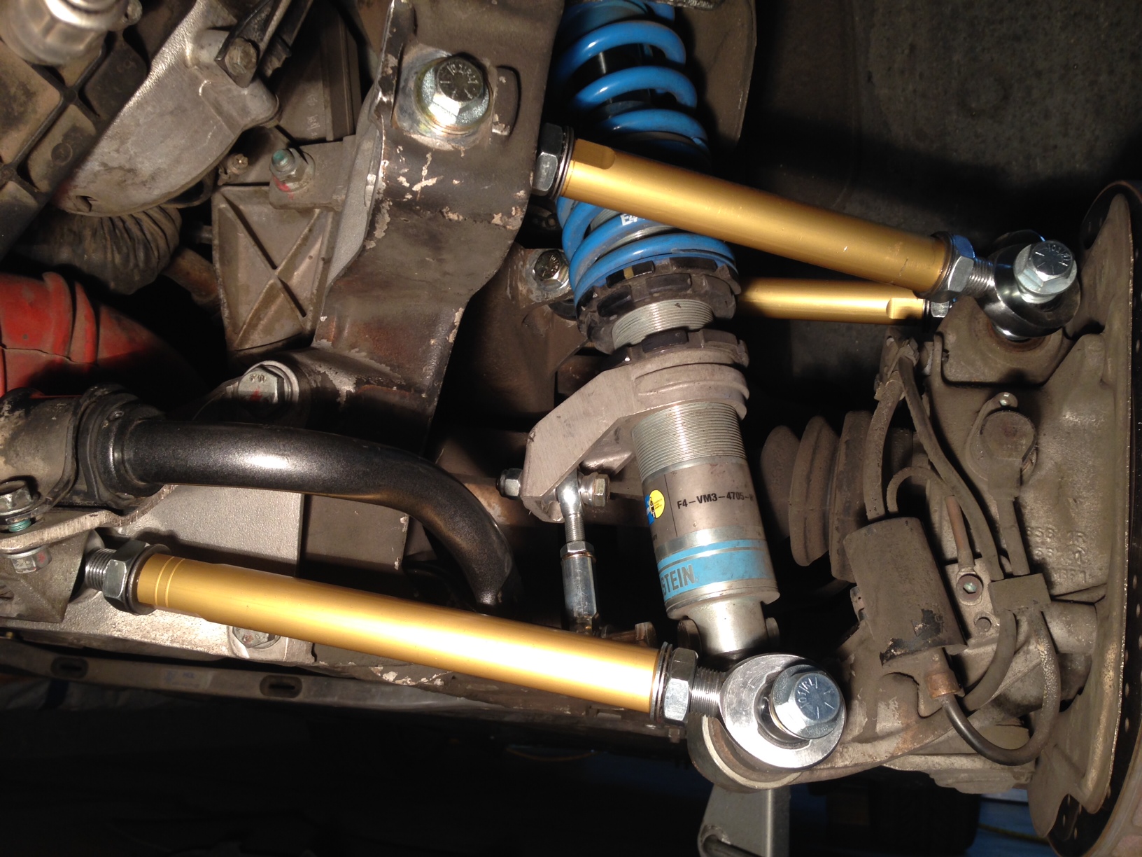
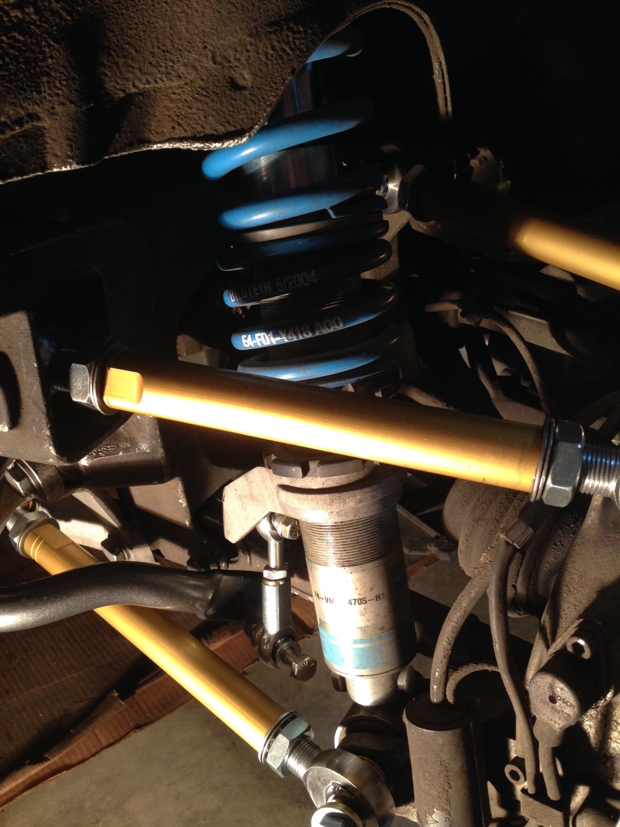
Wanted to do this for some time but couldn't afford or justify the cost to buy one of the kits available. I was able to source all of the components needed from a few different places. All said and done, the out the door cost was under $400 bucks for all 6 arms. Fitment is just about done and just need to make the eccentric locks. I'll keep you posted. I know, I know.... I'm not concerned with NVH. 
[ATTACH]785795[/ATTACH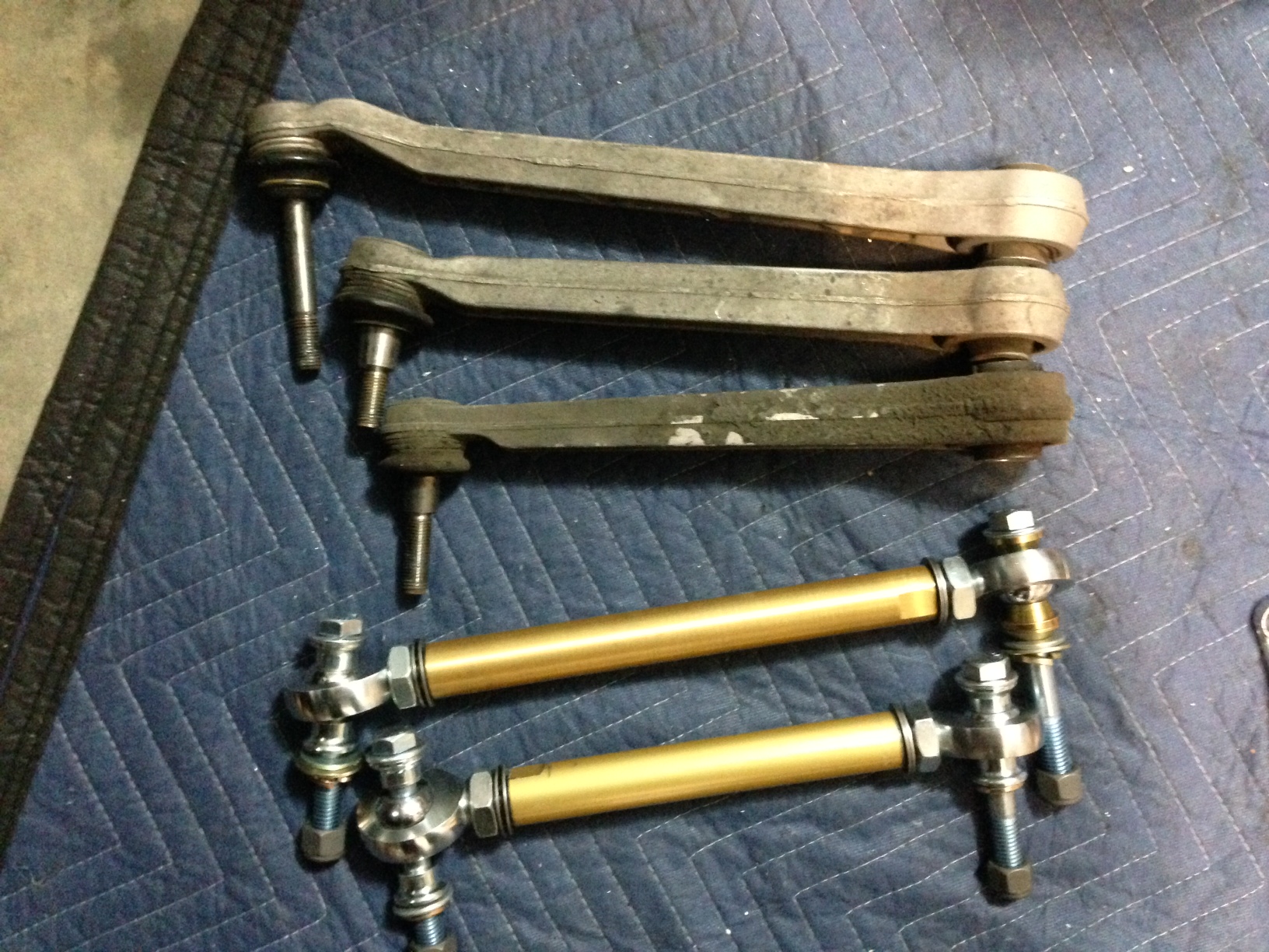
[ATTACH]785795[/ATTACH
 12-10-2013, 11:10 PM
#3
Rennlist Member
Great job!
I always thought the ones available from the usual suspects could be recreated with a little research. I've wondered though weather we know what forces are involved and how well the components are tested cf stock components. The stock components look strong, my aluminum links are thinner and don't look as robust as stock. A friend of mine had a aftermarket control link break at the track, he was lucky and didn't have any significant damage. The vendor and shop claimed bad batch and replaced everything for free on both sides but I still wonder if theses upgrades in general are up the task/engineered properly?
I always thought the ones available from the usual suspects could be recreated with a little research. I've wondered though weather we know what forces are involved and how well the components are tested cf stock components. The stock components look strong, my aluminum links are thinner and don't look as robust as stock. A friend of mine had a aftermarket control link break at the track, he was lucky and didn't have any significant damage. The vendor and shop claimed bad batch and replaced everything for free on both sides but I still wonder if theses upgrades in general are up the task/engineered properly?
12-11-2013, 12:11 AM
#4
Rennlist Member
Thread Starter
Join Date: Nov 2010
Location: Central California
Posts: 3,484
Likes: 0
Received 13 Likes
on
12 Posts
I was concerned about their integrity also. I found the available kits were 5/8" tubes and 1/2 rod ends. I went with 1" O.D. X 3/4" I.D. 6061-T6 aluminum tubes and 3/4" X 1/2" bore chromoly steel rod ends. 1/2" grade 8 hardware all the way around. The stock units have 12mm & 14mm bolts. I over bought parts. I wanted to be sure I had an assortment of spacers, washers and bolts so I could get the correct fitment the first time. Was scared of being stuck needing to go get it, or worse having to order it. Upon disassembly I found the mounts for the stock arms were nominal and believe my control arms are way over-sized. The front camber mount is pretty light. If you're interested in tackling this PM me and I can probably guide you to the places I used ( about 4-5 different sources).
12-11-2013, 12:19 AM
#5
Rennlist Member
Thread Starter
Join Date: Nov 2010
Location: Central California
Posts: 3,484
Likes: 0
Received 13 Likes
on
12 Posts
I had initially bought 1" I.D DOM steel tubing and have the weld in bungs to fab the arms up. Once I saw how little strength was in the mounting points I went with the aluminum tubes. If I see any sign of stress or possible failure, I'll use the DOM steel tubing and get another alignment. I'll keep you guys posted.
12-11-2013, 03:37 AM
#6
Rennlist Member
Sounds good, from the pics, your components do look pretty beefy. I have tarret and ebs parts, the tarret control arm ( the one by the sway bar) is the smallest dia and the others are larger, with the top rear one that comes closest to the spring largest. On my friends 997.2 gt3 rs, it was one of the bolts at the control arm that broke (can't remember which brand it was, but I understand they were all recalled and replaced as there were a few more that broke and his was we believe the index case). I visually check all my parts every time I take the wheel off (which is quite often!).
Trending Topics
12-11-2013, 10:08 PM
#8
Instructor
I don't want this to turn into an engineering review but here is some simple math for suspension links.
First off the weakest spot is "usually" the root of the rodend's thread. The best choice of material should always yield as opposed to breaking ( an obvious note ). A good steel rodend has a static load around 20,000 lbs. Now in simple rounded out terms. Your car weighs 4000lbs. You are cornering at 1G and you are doing it on one rear wheel. Lets say that wheel only has one link supporting it. The load will be 4000 lbs on the joint. In very simple math taking no other factors or events into account you have a 5 times safety factor. When you figure you have at least three wheels doing the work as well as multiple links sharing a portion of the loads at the corners, the loads are even lower.
Using quality rodends in the 13mm... 1/2" plus range is good for more than just piece of mind. The larger bearings have more surface area which gives them a greater life when used in street environments. Information to calculate the tubes, steel or aluminum are only a google search away.
Rick
The following users liked this post:
Coleman (01-03-2021)
12-12-2013, 02:08 AM
#9
Addict
Lifetime Rennlist
Member
Lifetime Rennlist
Member
I would have thought that consideration for other factors that are more dynamic also need to be considered, like impacts and shock loading - you do not want to hit a pothole at speed, and as the impulse travels through the suspension, peak past the yield or break strength of any of the components. I am not a mech though (but am a PE), so I am sure someone knows the math...
Cheers,
Mike
Cheers,
Mike
12-12-2013, 02:28 AM
#10
Rennlist Member
Thread Starter
Join Date: Nov 2010
Location: Central California
Posts: 3,484
Likes: 0
Received 13 Likes
on
12 Posts
Thanks Rick for the added peace of mind. I knew I was going overboard with the components, but like I stated before I didn't want to F everything up by installing lesser parts. In regards to potholes Mike. From what I seen in "the field" the usual yielding is in the form of a bent and/or destroyed rim with a blown out tire. I have seen cars "endo" from hitting larger holes at nominal speeds (35-45 mph). As soon as I get the locks finished I will load the final pics of the install.
Duece , my step son asked me if he could set up the instagram post. I don't do all that or FB and he was enthused about it so I let him have at it. Take care
Duece , my step son asked me if he could set up the instagram post. I don't do all that or FB and he was enthused about it so I let him have at it. Take care
12-12-2013, 02:40 AM
#11
Addict
Lifetime Rennlist
Member
Lifetime Rennlist
Member
cheers,
Mike
12-12-2013, 12:44 PM
#12
Rennlist Member
Thread Starter
Join Date: Nov 2010
Location: Central California
Posts: 3,484
Likes: 0
Received 13 Likes
on
12 Posts
You're right Mike about hoping the susp. bits could handle the force that would damage a rim. Alot of todays vehicles are engineered to have sacrificial components up front and in the rear (crumple zones) so the integrity of the pass. compartment is maintained. Body and paint shops love this. Not sure about insurance companies. They probably do so they can break it off in your a$$ when you file a claim. Sorry, 4got to curb my poor attitude :-)
 12-12-2013, 01:25 PM
#14
Rennlist Member
Thread Starter
Join Date: Nov 2010
Location: Central California
Posts: 3,484
Likes: 0
Received 13 Likes
on
12 Posts
Some have asked which parts I used and where they were aquired. No affiliation to any of the companies I bought from
Rod ends: QA1 3/4"X 1/2" bore RH # XMR8-12. LH # XML8-12
Tubes from Speedwaymotors. 4- 8"X1"O.D.X3/4"I.D. 2-9"X1"O.D.X3/4"I.D. Their part #'s are 91034134-8GS =8" & 91034134-9GS =9". They are on clearance so I can't be sure they'll still have them at $6.99 each. They're made by M&W aluminum products mwalum.com
Had to cut 1/2" off of each end to get 2 of them to 7" tubes. 8" is the shortest 1" tubes available. Don't cut 1" off of one end! The heim joint may not thread in all of the way :-( ooops. Good thing I bought extras. I then searched for 1/2" steel cone spacers and bought a few different types, thickness and brands because I couldn't find the assortment at just one place. Wanted some options on fitment so it would work the first time. The locks are 2"X2"x1/4" square stainless steel plate washers that are "really fun" to cut down to 2"X1.5" and trim so they fit correctly. The top portion of the eccentric lock is rounded and a square top won't work. Again, overkill on 1/4" thick. I probably would've been more than fine going with 3/4"O.D. X 5/8"I.D. tubes and then use the 5/8"X1/2" rod ends/heim joints. On the top 2 arms you'll need to fab a cone shaped insert for the 2 holes on the rear hub. The stock arms are tapered on the bolt from the ball joint. McMaster-Carr also have a very large assortment of EVERYTHING you would need regarding fittings. They're heim joints were a bit pricey. Hope this helps
Last edited by OverBoosted28; 12-12-2013 at 02:28 PM.
12-12-2013, 04:51 PM
#15
Rennlist Member
The 20,000 lb static load must also just be for inline forces and I would think there must be some other forces too. As I mentioned previously my friend's 'brand name' link failed/broke.