When you click on links to various merchants on this site and make a purchase, this can result in this site earning a commission. Affiliate programs and affiliations include, but are not limited to, the eBay Partner Network.
Okay, it's confirmed - the issue is with the VSS circuit of the speedometer. I jacked the car up to allow the rear wheels to spin and hooked up the scope. There is a perfectly beautiful input signal on pin 4 and no output on pin 2.
I couldn't find much info on repairing the circuit, only on replacing the odometer gear. Any advice here is highlyappreciated.
Good test! Lift the wire off Speedo PIN 2 and measure PIN 2 on the speedo again. It's possible the speedo's ok but there's a short to gnd on the pin 2 "A" bus. It does go to a lot of devices. You could also lift the connector off the speedo and ring resistance from Pin 2 to gnd looking into the mating cable.
Good test! Lift the wire off Speedo PIN 2 and measure PIN 2 on the speedo again. It's possible the speedo's ok but there's a short to gnd on the pin 2 "A" bus. It does go to a lot of devices. You could also lift the connector off the speedo and ring resistance from Pin 2 to gnd looking into the mating cable.
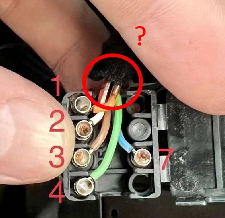
You are a genius! I just checked resistance between these pins and found that the pins 2 (VSS output), 3 (ground) and 7 (light bulbs) are all connected/shorted. This is with the ignition off and the speedometer, tachometer and clock unplugged I checked the connector itself, it looks fine.
I guess the next steps are to study the wiring diagram and start unplugging every device connected to pin 2. Any other suggestions?
OK, 2 and 3 are shorted looking into the cable plug. The signal on 2 goes to a lot of places in the car. Try the easy one first -the OBC connector right next to it. Unplug it and with the 5 pin connector plugged back in, see if you get a signal on speedo 2.
OK, 2 and 3 are shorted looking into the cable plug. The signal on 2 goes to a lot of places in the car. Try the easy one first -the OBC connector right next to it. Unplug it and with the 5 pin connector plugged back in, see if you get a signal on speedo 2.
I already tried that. Unplugging the OBC connector (the one on the back of the tachometer) didn't help. I also completely unplugged the clock and the speedo. The pins 2 and 3 are still shorted. Having a really hard time understanding the wiring diagram :-( Please give me more ideas about what to unplug and where to look for it.
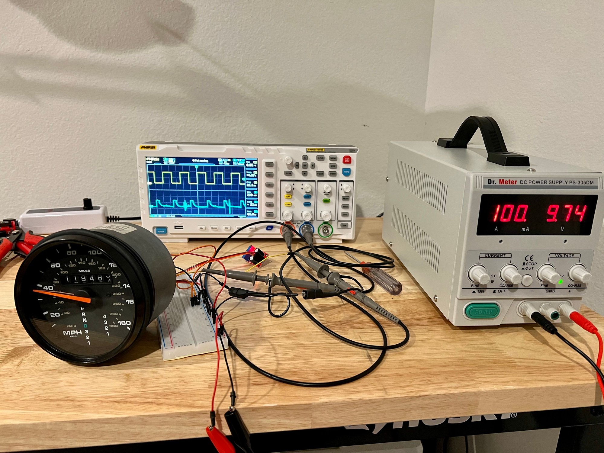
Building a bench test harness for the speedometer in parallel. It seems simple enough to do just for fun and see the desired output (I could do it in the car by disconnecting pin 2, as you suggested, but it requires having the car on jack stands which is a bit of a hassle in my garage).
Indeed. If it were me....and before tearing into things, I'd want to first satisfy myself that the the speedo is able to put a signal out on Pin 2 with nothing attached to it. Plug everything together, lift the wire on speedo 2, get the wheels moving, and look at speedo 2. I keep coming back to how this all started - you disconnected the gauges then put them back together. Given that, it's unlikely (not impossible) that a short developed somewhere in the bowels of the car. It's an easy test, and could save you a lot of work.
Indeed. If it were me....and before tearing into things, I'd want to first satisfy myself that the the speedo is able to put a signal out on Pin 2 with nothing attached to it. Plug everything together, lift the wire on speedo 2, get the wheels moving, and look at speedo 2. I keep coming back to how this all started - you disconnected the gauges then put them back together. Given that, it's unlikely (not impossible) that a short developed somewhere in the bowels of the car. It's an easy test, and could save you a lot of work.
Fair enough. It�s easier than trying everything else and is a good sanity check. Will do.
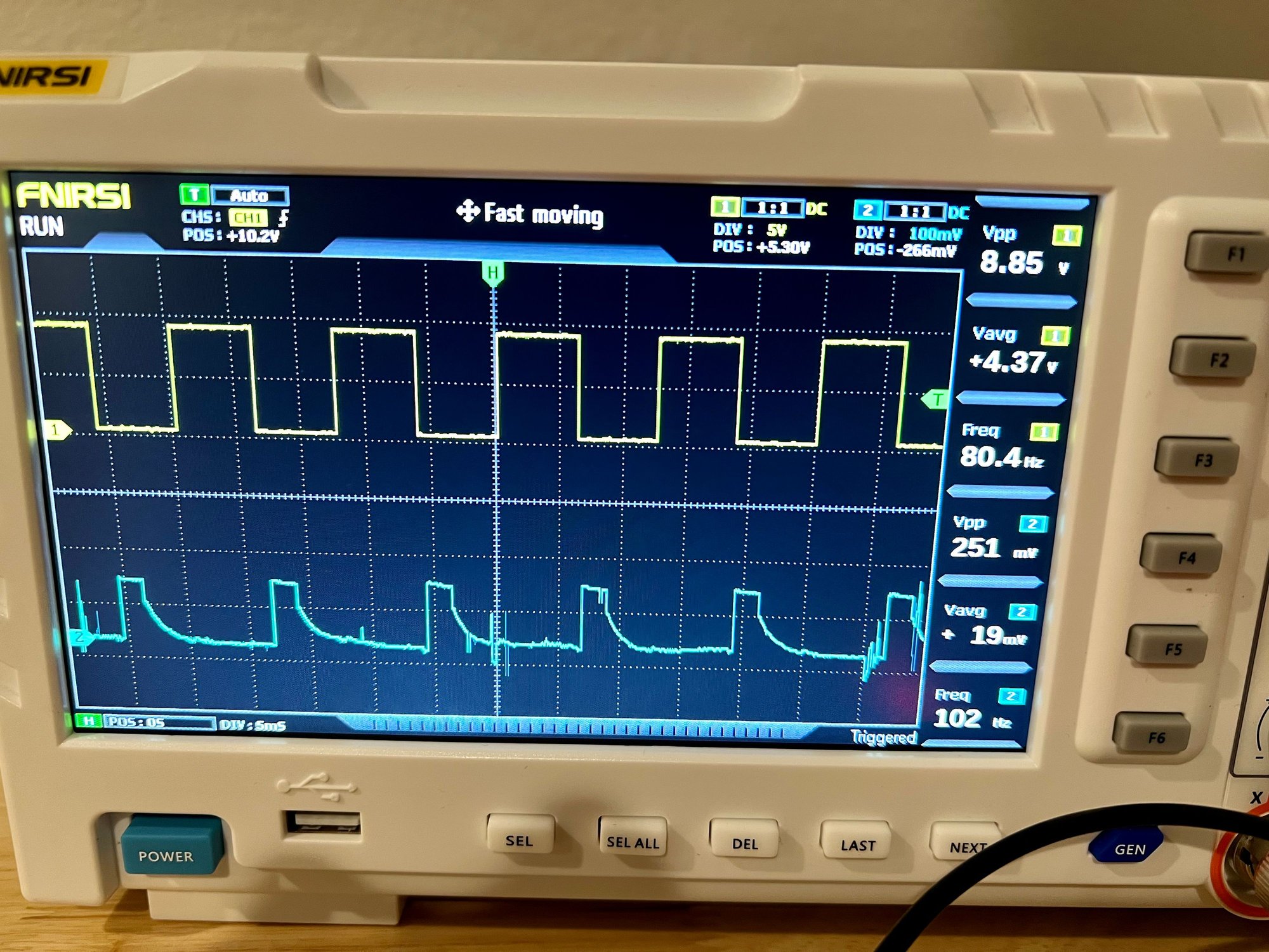
Channel 1 (yellow line) on the scope is the square wave input signal on the pin 4 generated by NE555. The speedo correctly recognizes it as ~40mph. The output from pin 2 is this strange thing observed on the channel 2 (blue line). Is this what it is supposed to look like?
You will probably not have a reliable function of the speedometer with a 9V supply.
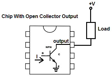
As far as I remember is the vehicle speed pulse an open-collector output. Try to tie the output to +12V with a 10k resistor. The pulse shall be a 12V p-p signal.
Cheers,
Tore
You will probably not have a reliable function of the speedometer with a 9V supply.
As far as I remember is the vehicle speed pulse an open-collector output. Try to tie the output to +12V with a 10k resistor. The pulse shall be a 12V p-p signal.
Cheers,
Tore
I tried to replicate the input signal I recorded in the car. Changed the power supply to 12V and 12VPP signal. Same picture.
Do you mean I should supply +12V to pin 2 through a 10k resistor? Like this?
Yes, as far as I remember is the VSS output terminated with a resistor to +12V in the units that receives this signal. Using the speedo outside the car will therefore need this termination.
I'll have to locate my notes on this, but i think the VSS output is in phase with the ABS input, but with different pulse length.
Cheers,
Tore
Thank you! It worked! The output looks like PWM. The duty cycle changes proportionally to the vehicle speed.
It seems my speedometer is fine after all. Has to be a short somewhere else.
Good! I was actually suggesting to test it in the car with everything connected and just lifting the wire off pin 2, but this works. Thanks for jumping in Tore. Now the search begins.
Quick question: is that bare wire? Maybe peel the tape back a bit and have a better look?


 I checked the connector itself, it looks fine.