When you click on links to various merchants on this site and make a purchase, this can result in this site earning a commission. Affiliate programs and affiliations include, but are not limited to, the eBay Partner Network.
DIY: Removal of Intake Manifold (96+) and SAI pump fix (Pic intensive)
Hey all, I just wanted to share my DIY that I spent the last three days on. Before I begin, I wanted to give a huge shout out to fellow RL member @swmic . He really took the time to walk me through each step as well as field numerous phone calls from me throughout the weekend. Huge thanks to you sir!
Background: This all started when I bought my 98 c2s earlier this summer. I was tracing down the CEL codes P0410 and P1411, which is indicative of an issue with the SAI system. I�ll create another thread about my experience with troubleshooting it but long story short, there are only a handful of things that can go wrong that will throw this code. For me, I believe the culprit was my SAI pump b/c I could see that the coating on the wires have deteriorated. So I tried last weekend to pull the SAI pump without taking off the intake manifold but unfortunately, it is not possible.
So for the next week, I scoured RL for tricks on how to do this trying to figure out what was involved and what the risks were. My MO is to visualize every step and if there�s a step that I don�t think I could do, I�d take it to the shop. Btw, I got a quote from a local shop that I trust and they quoted me $400 to take out the pump, fix the wiring and re-install. Personally this seemed to be a very fair price but I wanted the feeling of �finally� fixing this SAI issue that I�ve been chasing for months.
So after hours and hours of research (and some sleepless nights), I took Friday off and went to work.
Here are the general steps. I tried to take as many pics of �importance� that I could but obviously proceed at your own risk!
Disconnect the battery
Take out Airbox and MAF sensor (Passenger side). There are countless threads on this so not going to go into detail.
Take off blower motor (driver side). Also countless threads on this so not going to go into detail.
ENGINE DROP
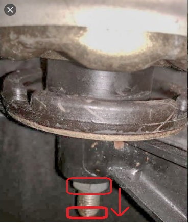
Drop motor by loosening/undoing the two motor mount bolts. So for this step, I was concerned about dropping it too much and damaging something that I would majorly regret. Some folks totally took the nut off the motor mount and very slowly dropped it 3-4�. However, I felt comfortable only dropping the engine with the nut still attached to the bolt of the motor mount so I was only able to get ~1.5� drop. I was very concerned that this would not be enough but thankfully, it was sufficient! Would dropping it more help make it easier�absolutely! But I just wanted to do the minimum just to be overly cautious.
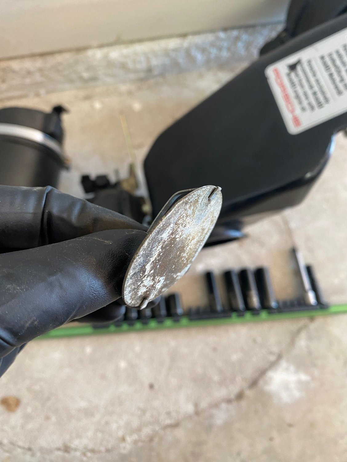
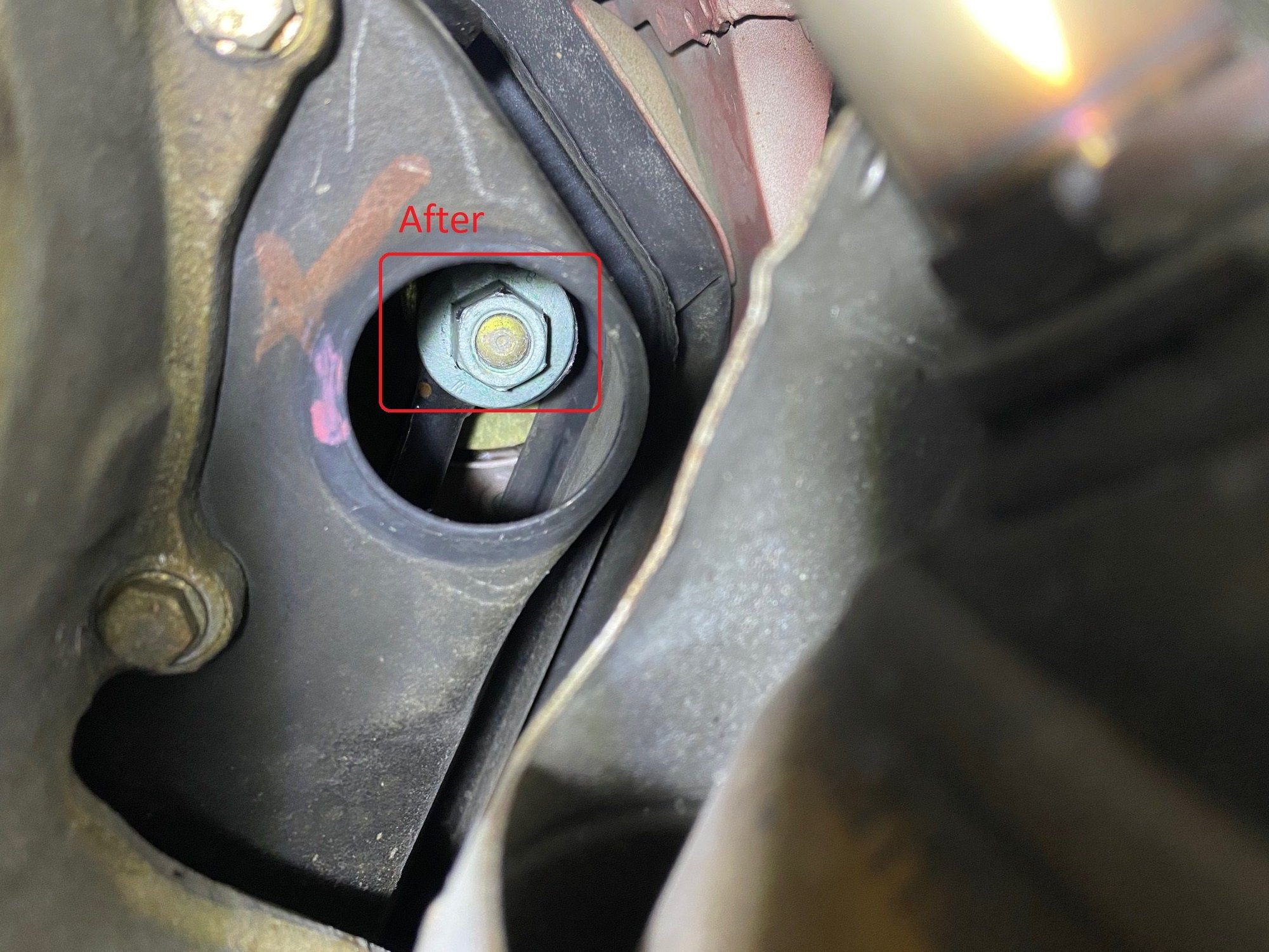
When you get underneath the car, you may see this circular plug. You will need to remove it to get access to the motor mount. The plug has two metal bars. Push that in toward the center of the circle and it should pop off.
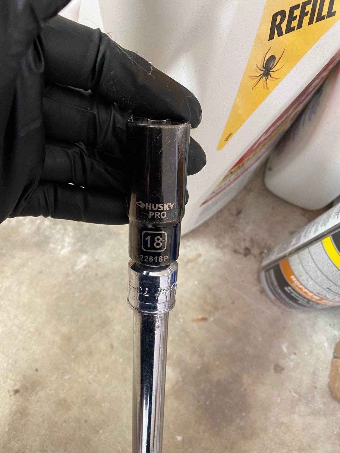
Use an 18mm socket to loosen the bolt.
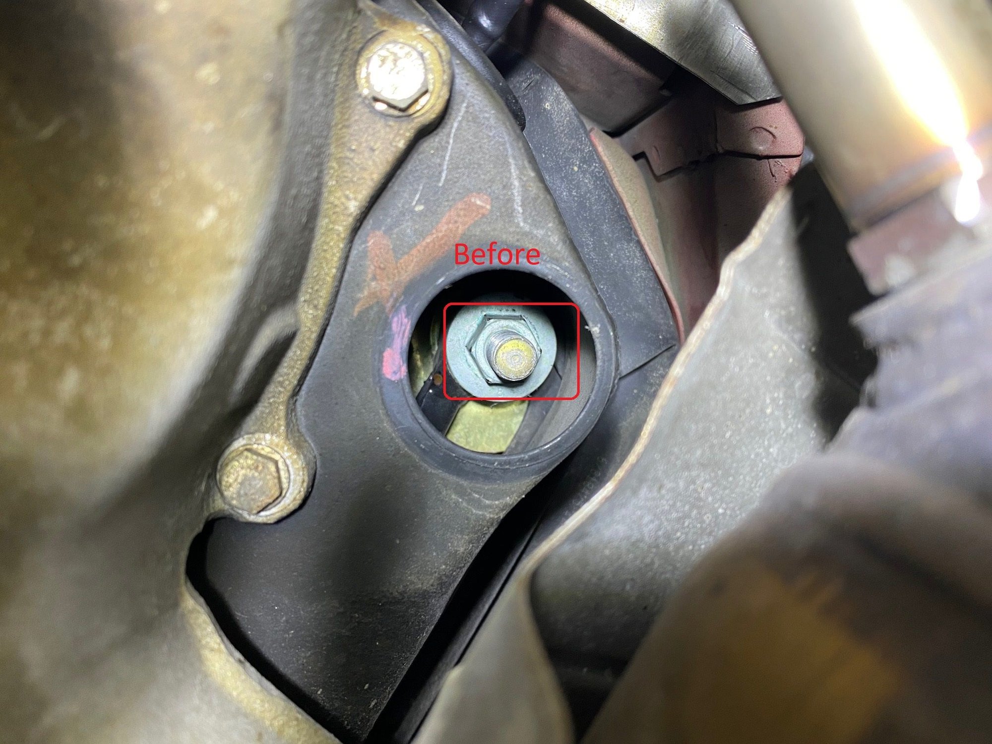
Here are before and after pics of the bolt on the motor mount.
Also, it�s worth noting that I had a jack underneath the engine.
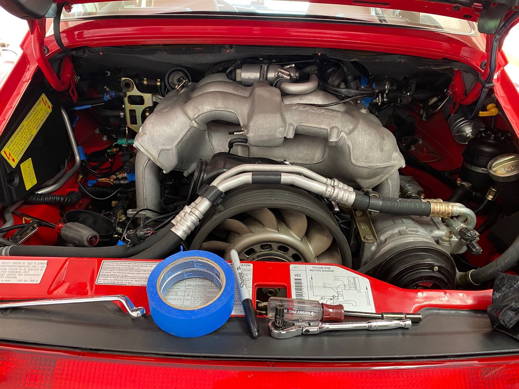
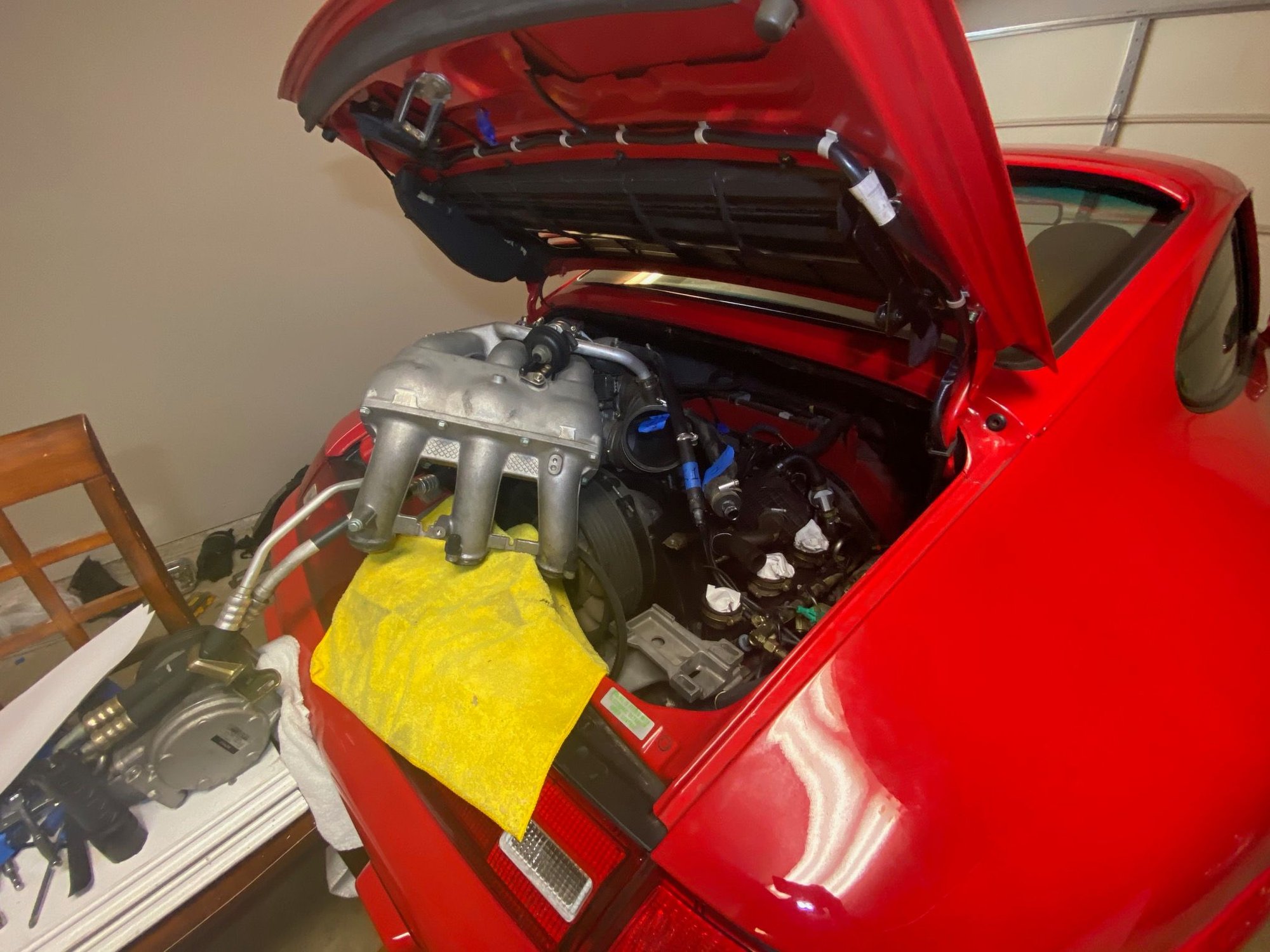
Now that you�re taken out the airbox, blower motor and dropped the engine 1.5�, it should look something like this.
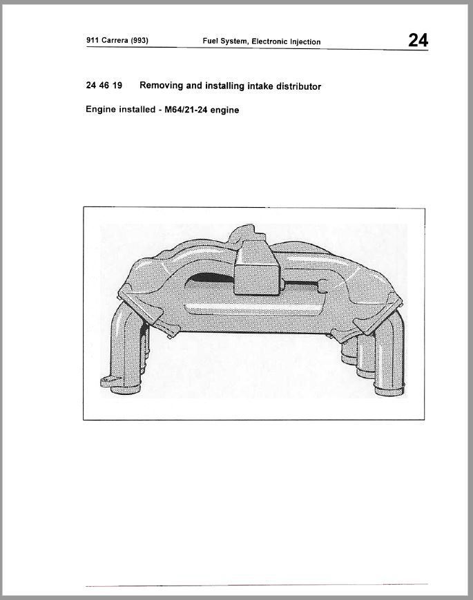
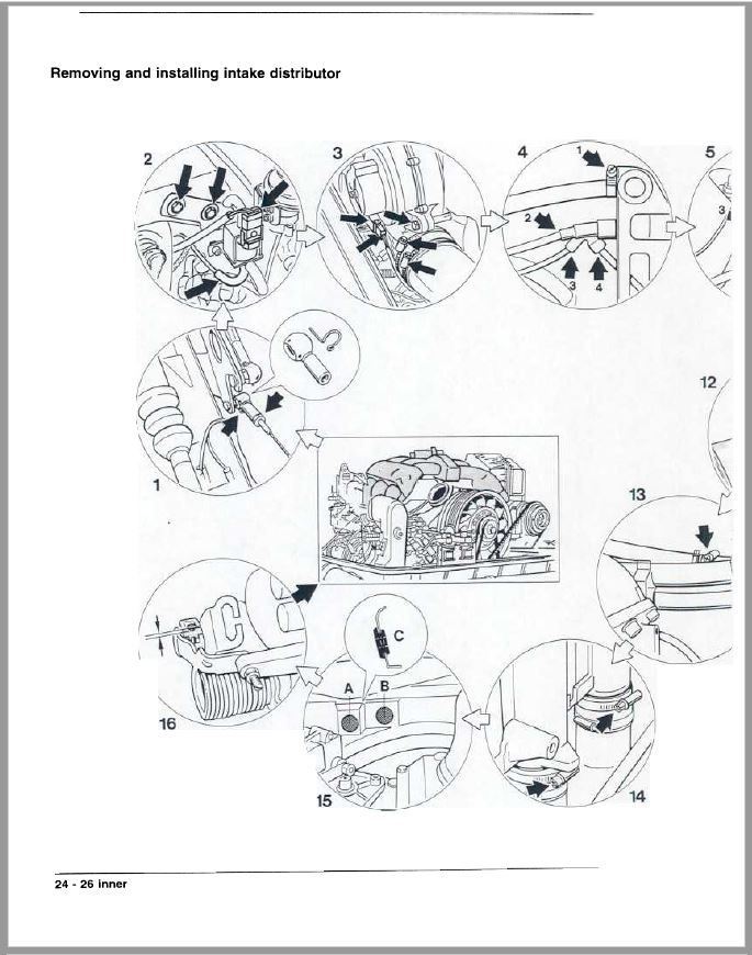
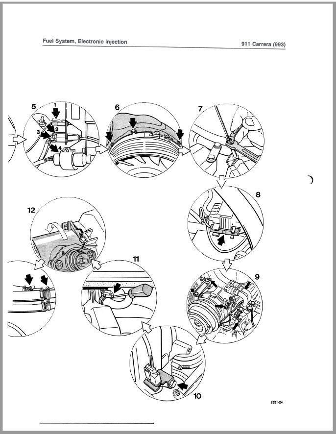
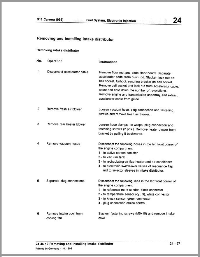
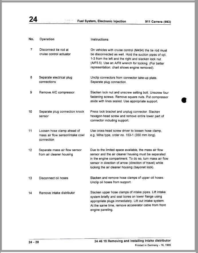
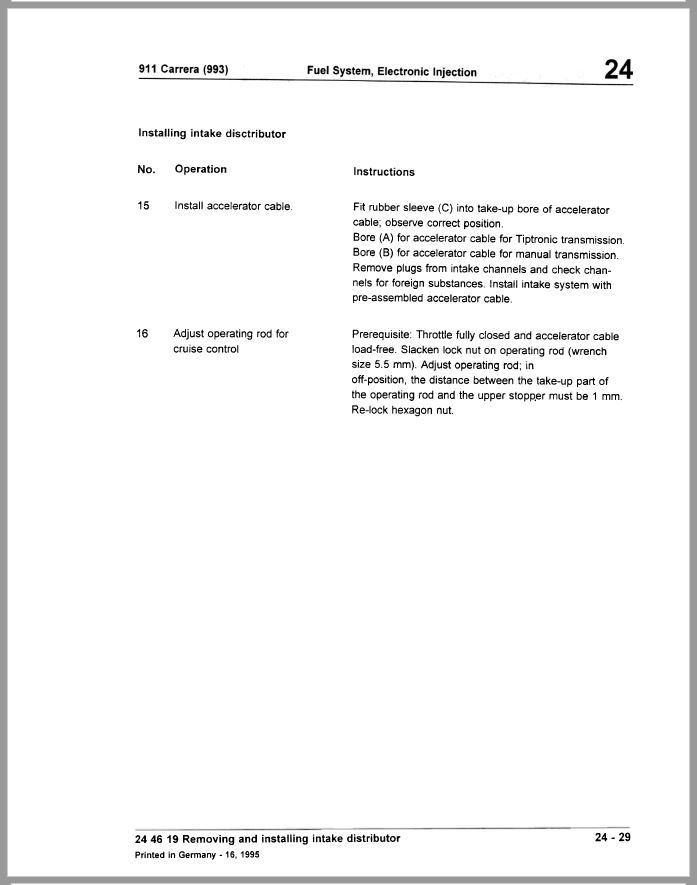
Here are the steps from the shop manual. As you can see, I deviated from some of it (esp the throttle and cruise control cable part).
Reinstall should be pretty simple. Take your time. Make sure you do not pull hard on the throttle cable.
The End.
I hope someone finds this helpful and informative. I know I'm missing a few folks but thanks again to everyone who helped me with this DIY ( @pp000830 , @bobt993 , @Churchill , @ToSi , @XLR8 , @RobinSun, @AOW162435 and last but not least, to @swmic .
I definitely would not have bought the 993 if it wasn’t for the RL family and us journeying together through our ownership. God bless!
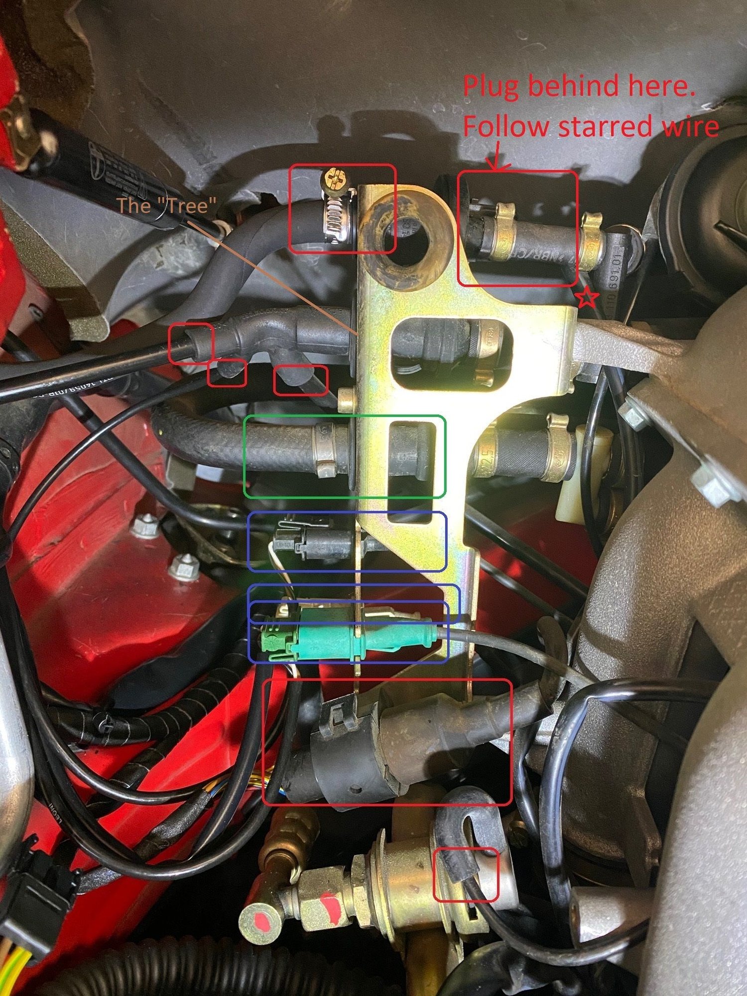
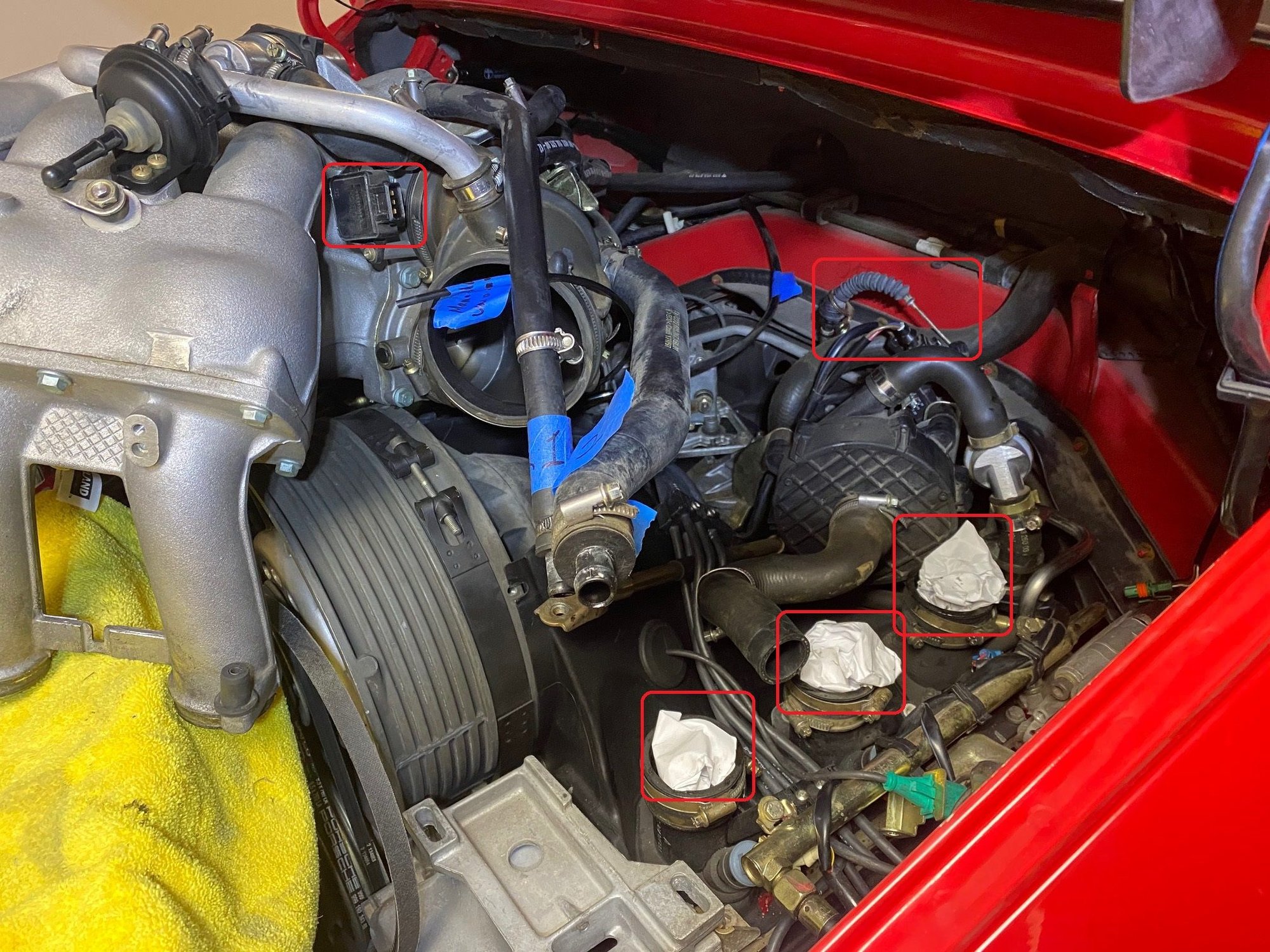
Next, lets start on the driver side. It looks pretty messy here but really not too bad.
The key here is to take your time to unplug things b/c if you rush and accidently damage a plug or inadvertently pull off a vacuum line by accident, you’ll spend a lot more time trouble shooting how to fix it.
The pic below shows some of the things that need to be disconnected. For me, every piece that I disconnected, I labeled with painters tape and a simple note to help. If you get lost, most of the plugs/lines are either color coordinated, plug-specific or line OD specific. However, it’s still good to make notes to be overly cautious.
FYI, the brass bracket is commonly known as a the “Tree.” You do not unbolt this to take off the manifold but later on, I did unbolt it to give me more access to address the throttle cable (much more on that later).
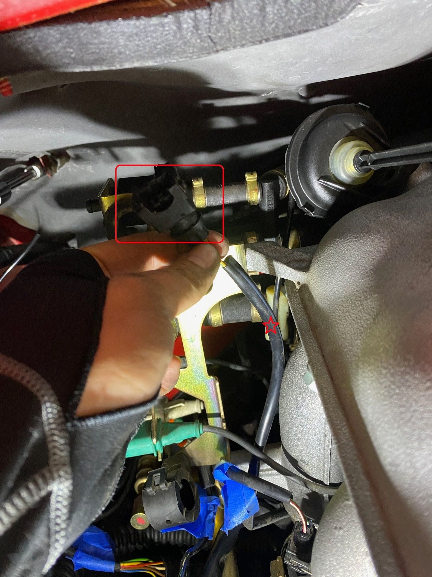
A few things to note, there is a plug on the top right of the Tree that needs to be disconnected. Hard to see but if you follow the “starred” wire, you’ll see it.
For the plugs in circled in blue, you will not only need to unplug it but you’ll need to unclip it from the Tree. Be careful sliding it out as the clips wedging it to the Tree is very brittle (ask me how I know).
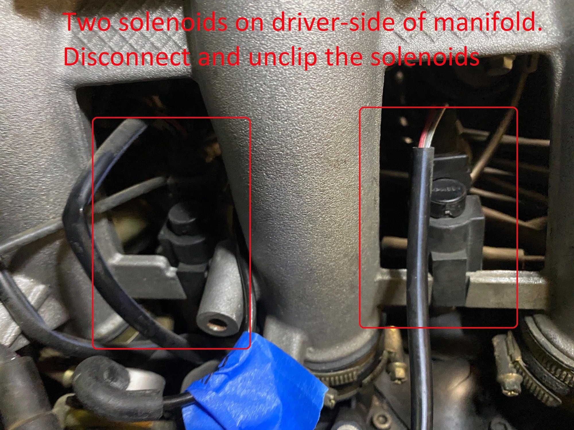
There are also two solenoids on the side of the driver-side manifold. Disconnect the plug and unclip the solenoids off the manifold.
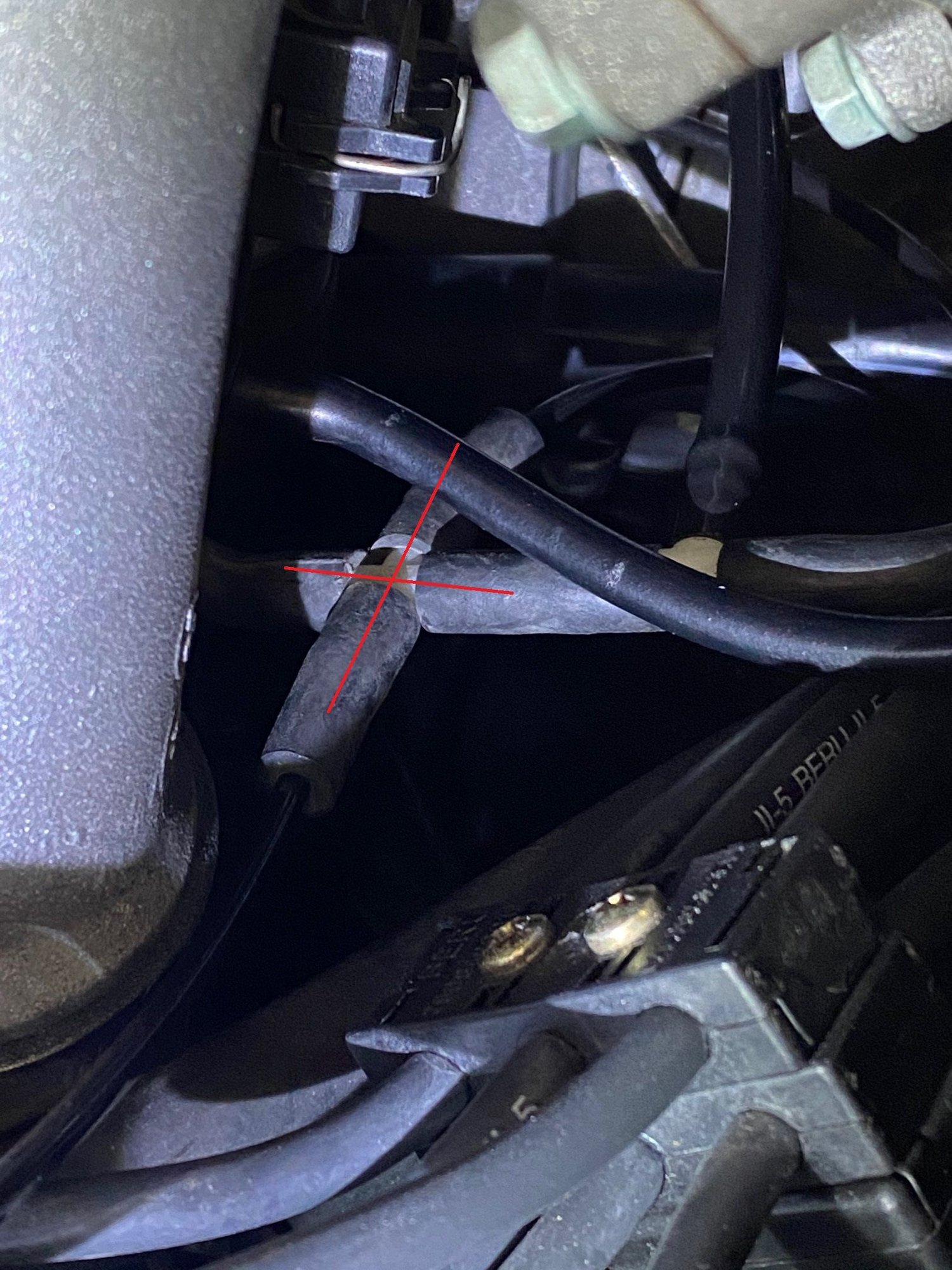
Also, pay attention to the “Plus” and “Tripod” vacuum hubs (not sure what the technical term is) underneath the manifold. It will be a good thing to make sure that all the connections on these two hubs are snug and plugged in. Also, will be a good check to trace where they go and make sure the other end is snug a well. FYI, I accidentally had a vacuum line pop out on one of the legs of the Tripod hub. I noticed if when I was doing a final check so it does happen.
When you’re all done, the driver-side should look something like this
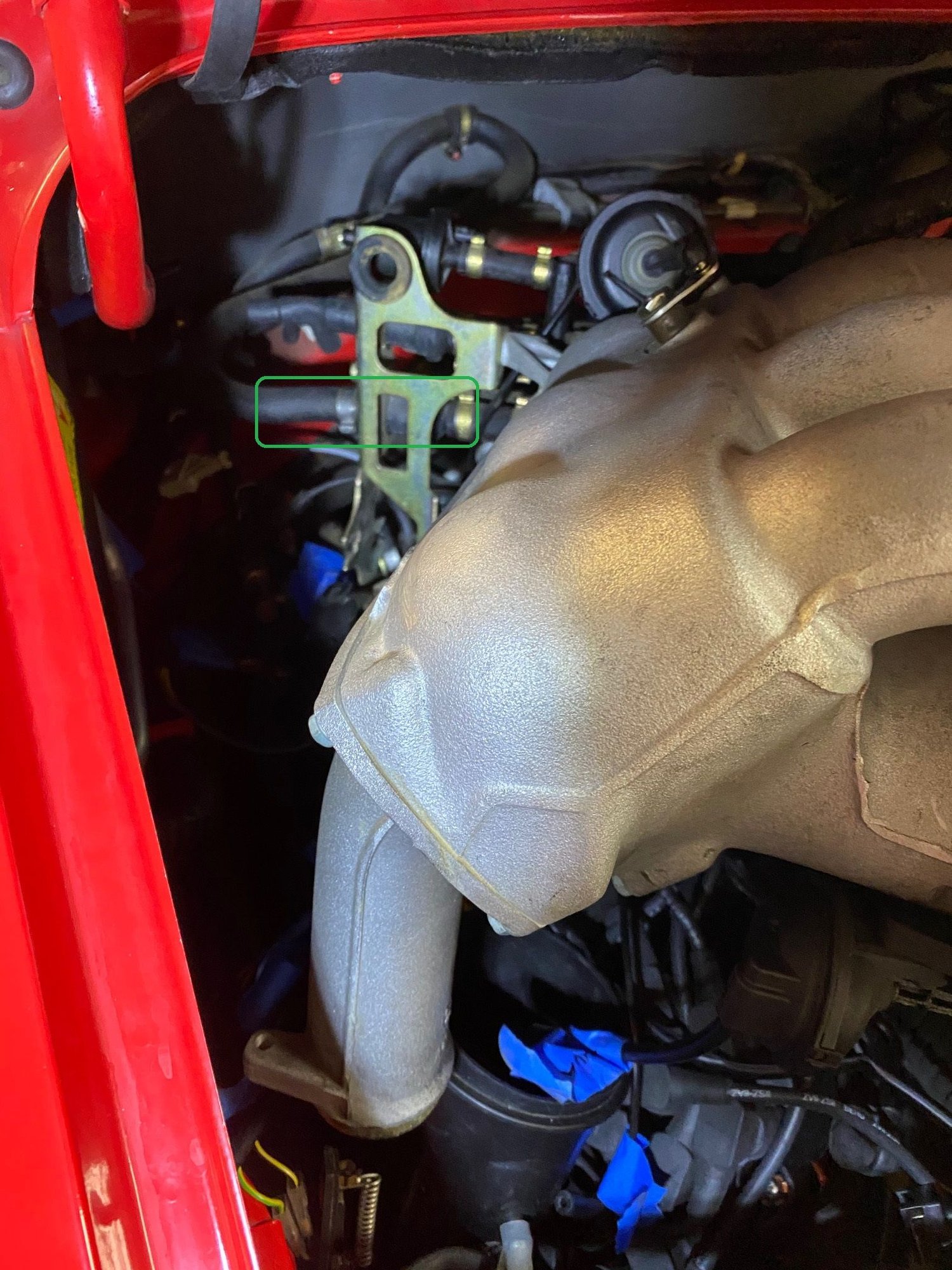
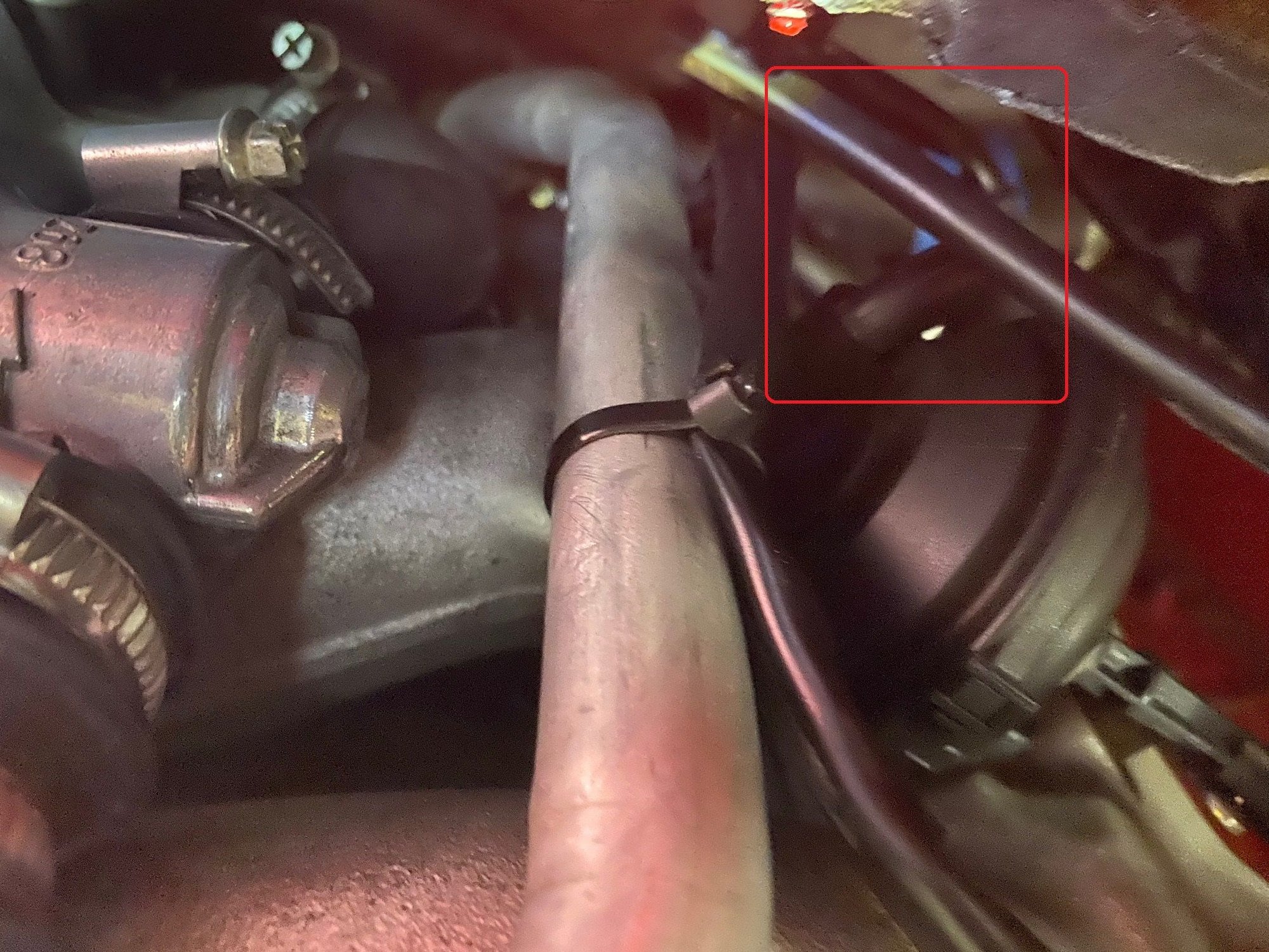
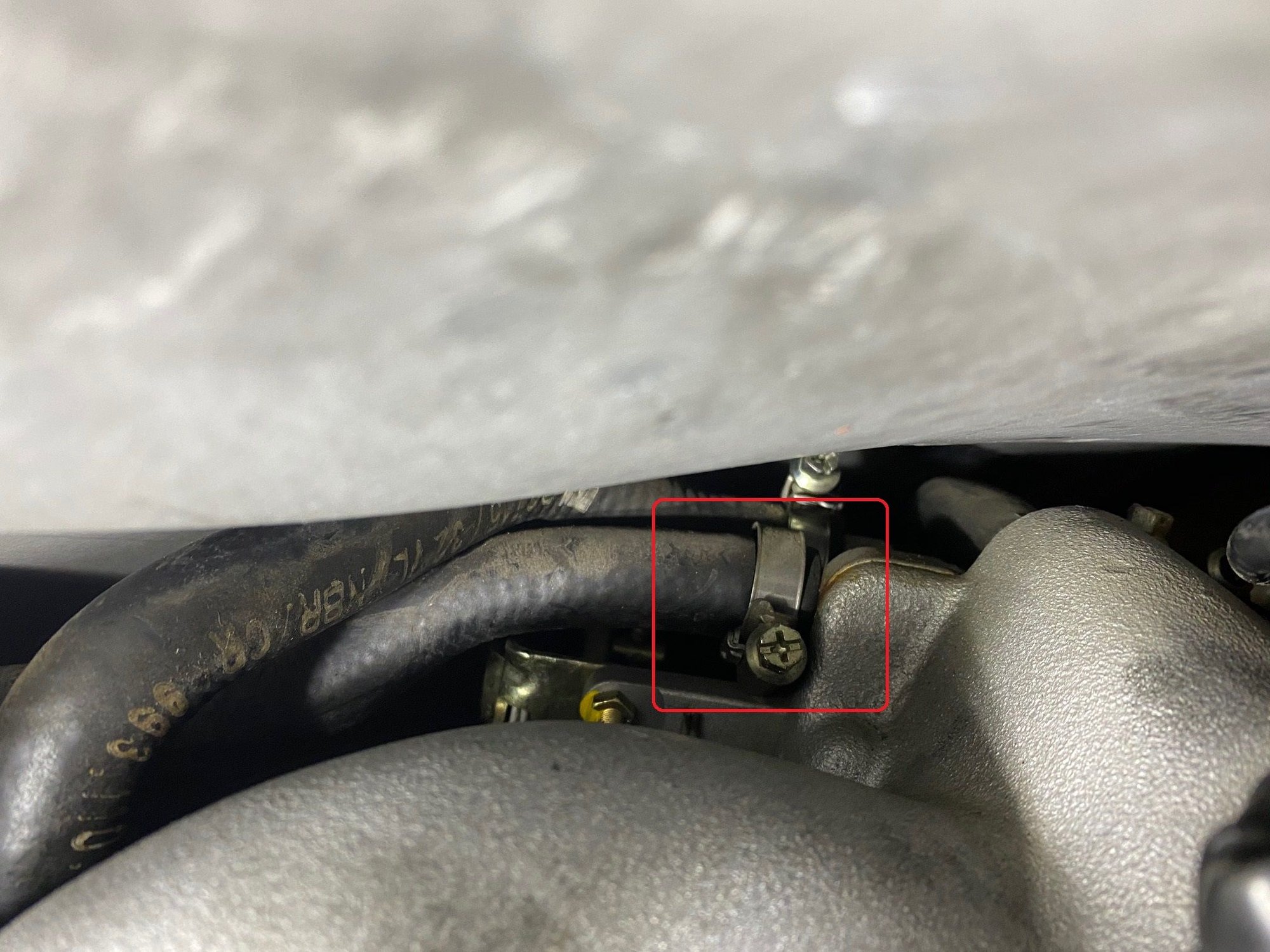
DISCLAIMER: See green box here… this one I did not take off b/c the locking clamp was not a simple screw on/off type. This prevented me from fully taking off the manifold. However, since my goal was to get access to take out the SAI pump on the other side of the motor, it was not a big deal.
Pretty much done with the driver side. Let's go to the passenger side
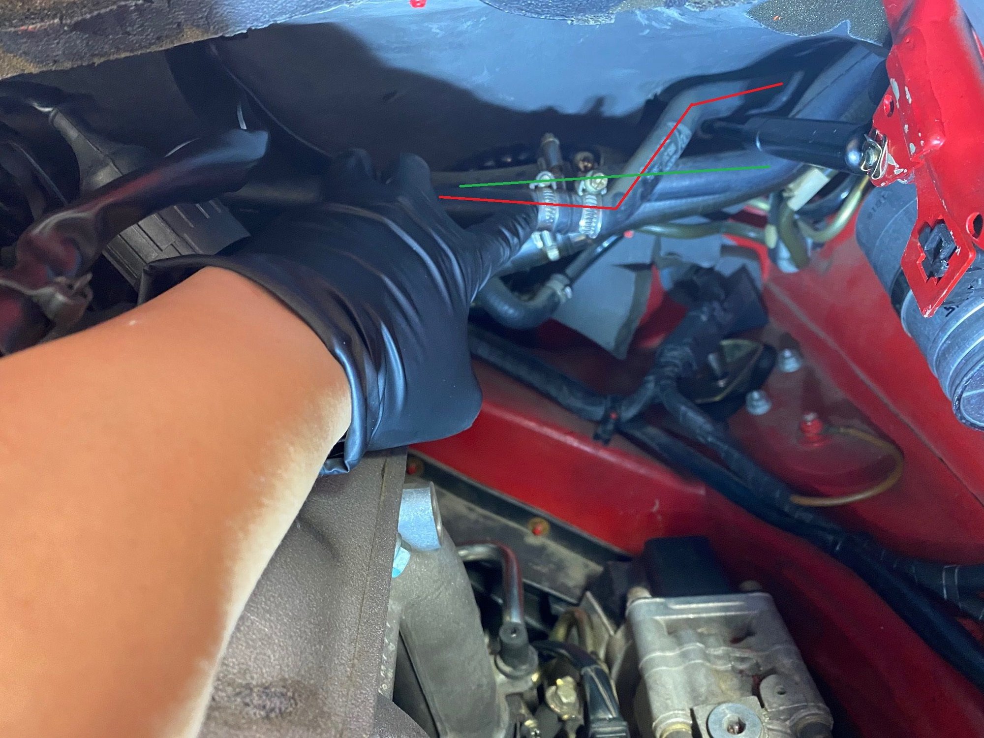
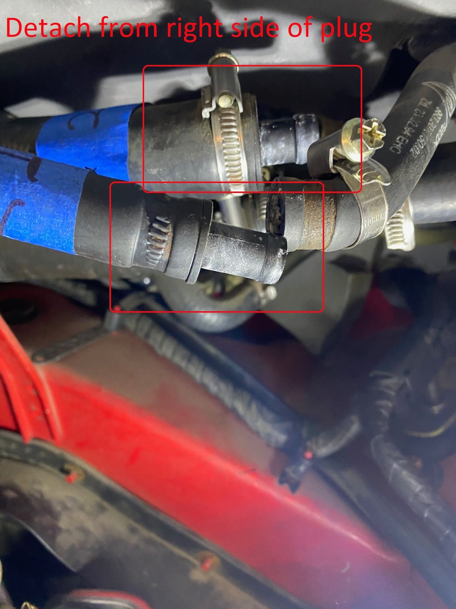
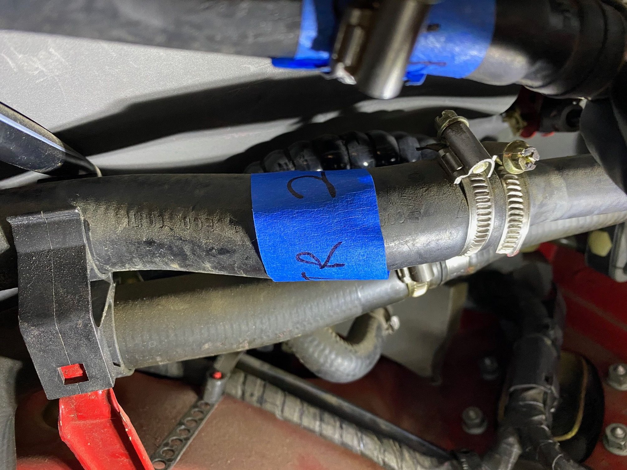
On the passenger side, once you take off the airbox, you will see two lines on top corner, far back right. Those two will need to be disconnected. I found out it’s easier loosening the right side clamps and pulling the right side off.
Don’t really need to here but I labeled the lines
On the backside of the manifold (passenger side) is a plug that will need to be disconnected. It’s literally sitting between the MAF and the manifold. Put a mirror back there and you can see it. Disconnect that.
Also, use a 10mm wrench and release the bracket for the green plug
Also on this same side of the manifold, there’s an actuator that has a vacuum line attached, remove the line. I labeled this b/c it can be easily forgotten
On the other (driver) side of the manifold is another vacuum line. Disconnect that as well (make sure to trace where the other end goes)
REMOVING AC COMPRESSOR
There are a bunch of DIYs on this but I would reiterate to pay attention to the square nuts on the bottom of the compressor. There will be four of them. Make sure you catch them before the bolt is fully loose or you will have a hard time fishing them out. If you do drop it, make sure you have some magnetic pens around (ask me how I know). Also, remember to disconnect the wire that’s running off the compressor
Here’s a pic of the base the compressor sits on. It slides left to right and is locked down by the 10mm bolt on the right
Also, take off the three 10mm bolts that holds down the plastic cover on top of the fan. This needs to come off to clear the way for the intake manifold.
At this point, once you loosen all six clamps on the intake manifold, you should be able to loosen it and move it out slightly. Be VERY CAREFUL how much you move it with the throttle and cruise control still attached. I’ve read people had to re-adjust the cable underneath the car (transmission tunnel). I initially thought I messed it up as well but ended up not *whew*
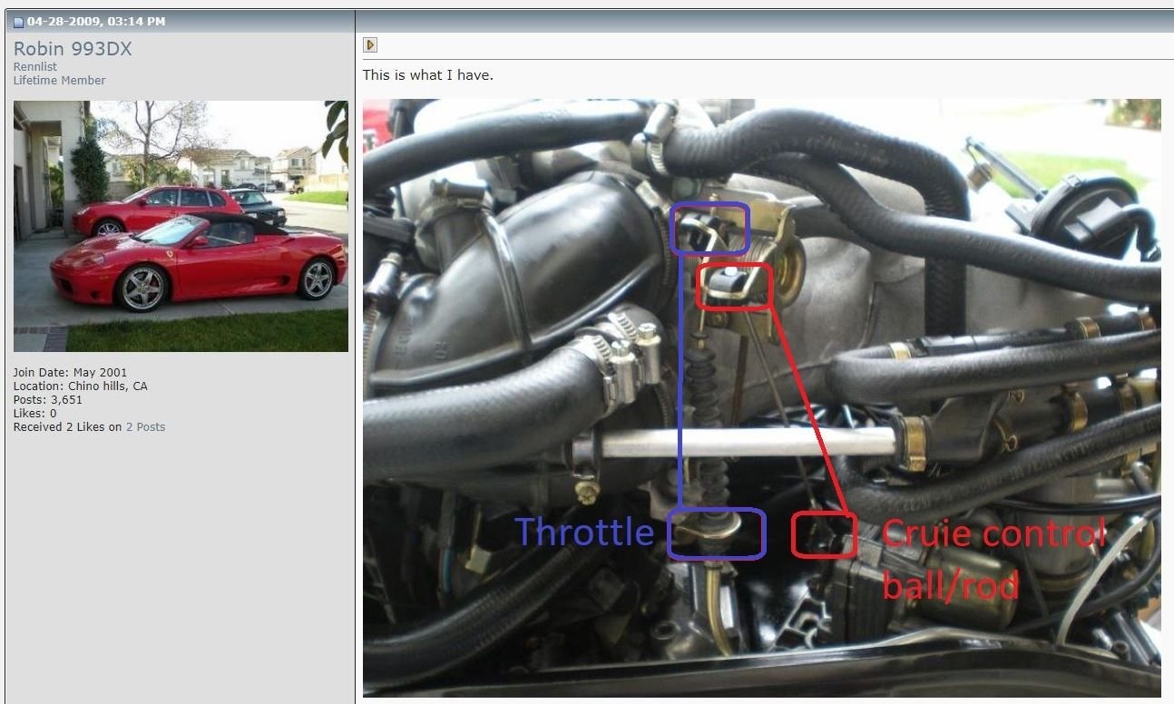
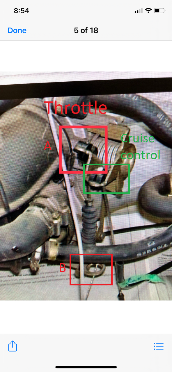
Here comes the hard part. At the back of the manifold are two cables that are attached. The throttle cable and the cruise control cable, which both need to be disconnected. I found it very helpful to �see� what we�re looking at. These pics were taken off of RL. One was from Robin�s post so credit to him
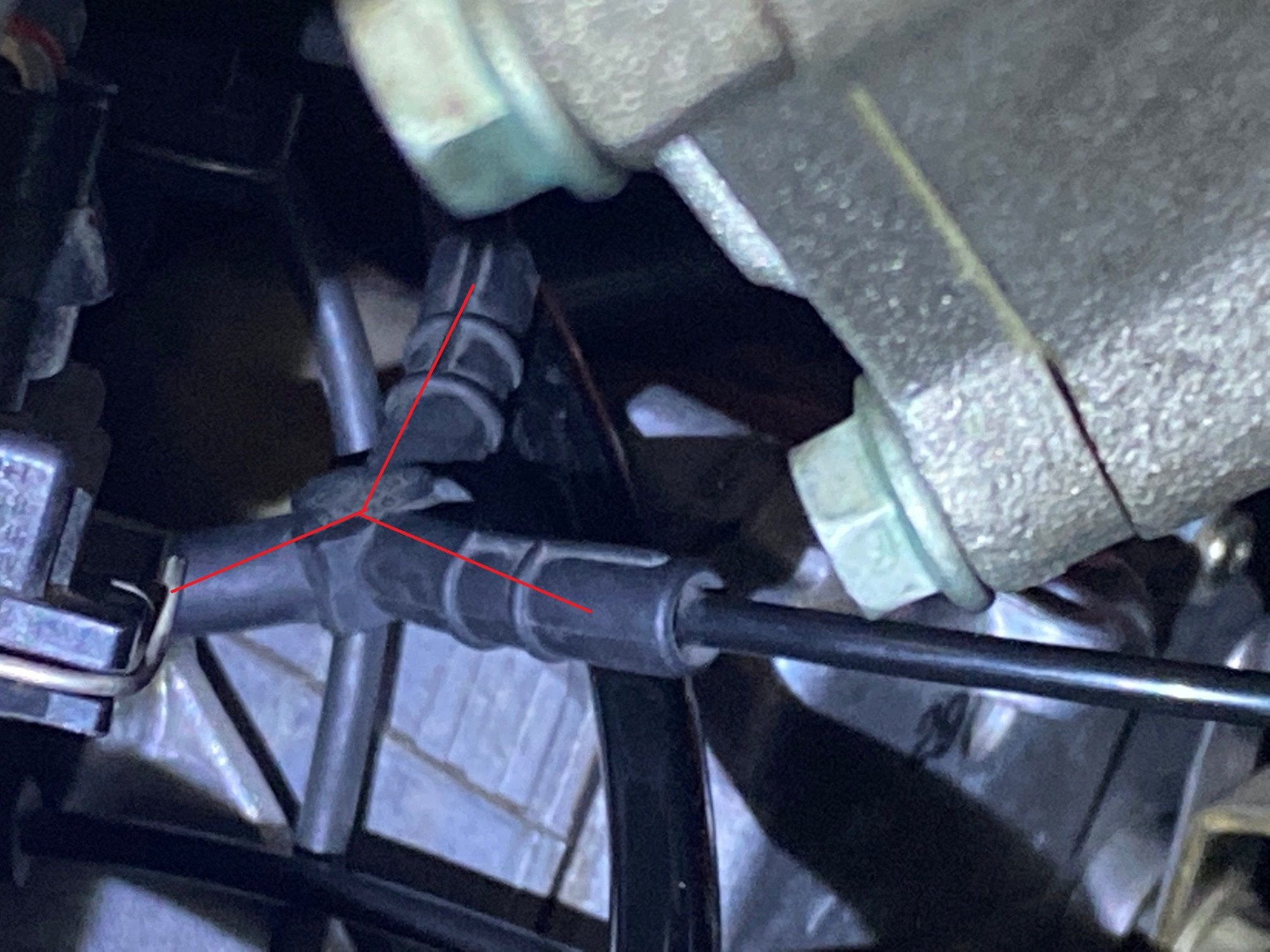
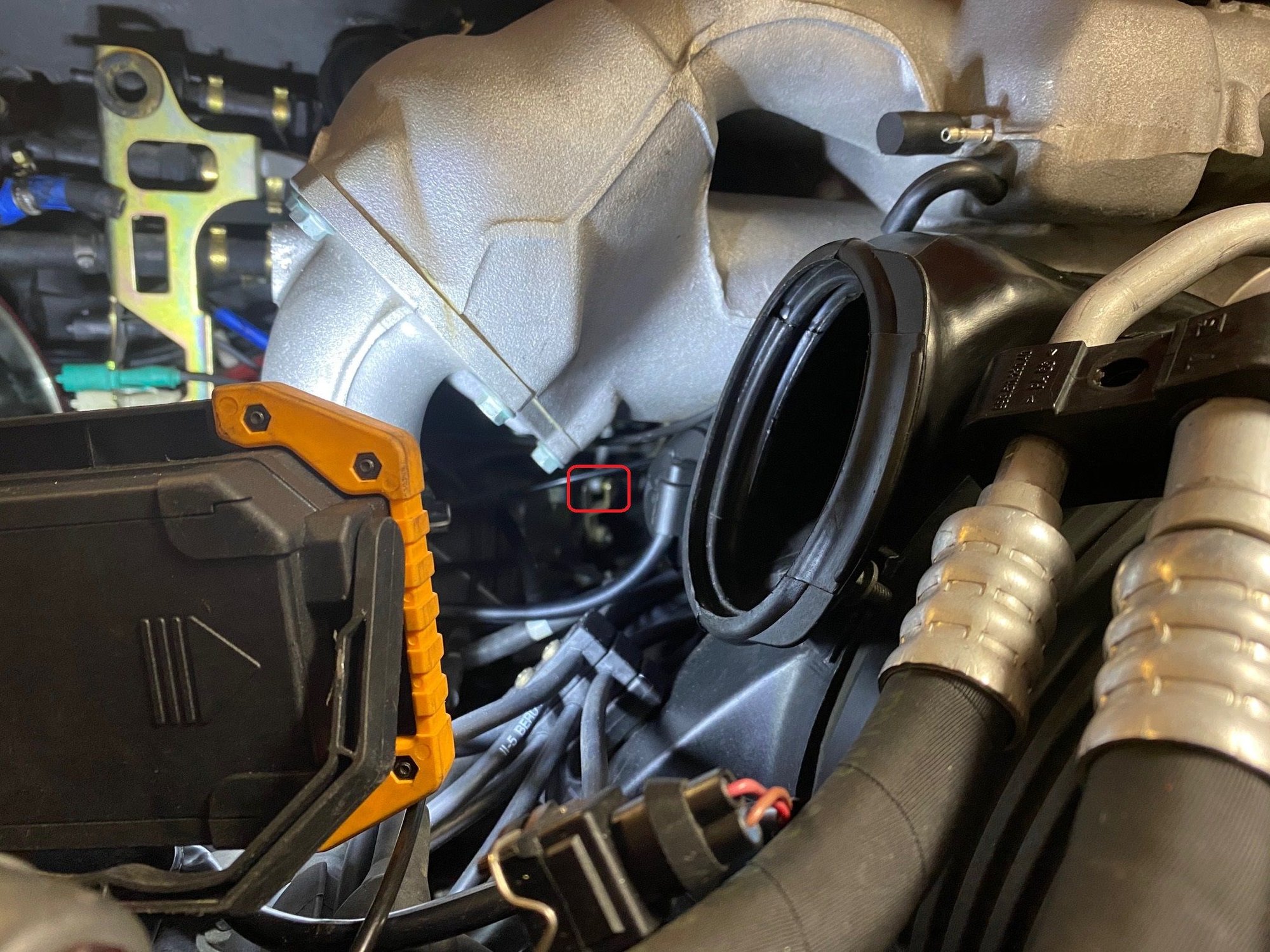
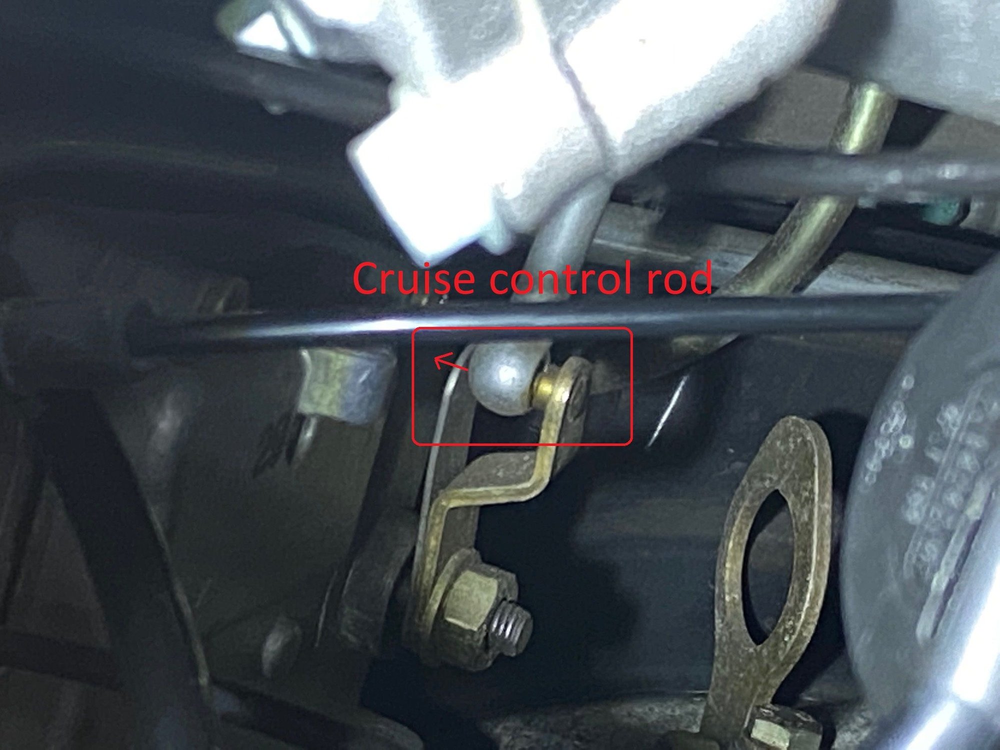
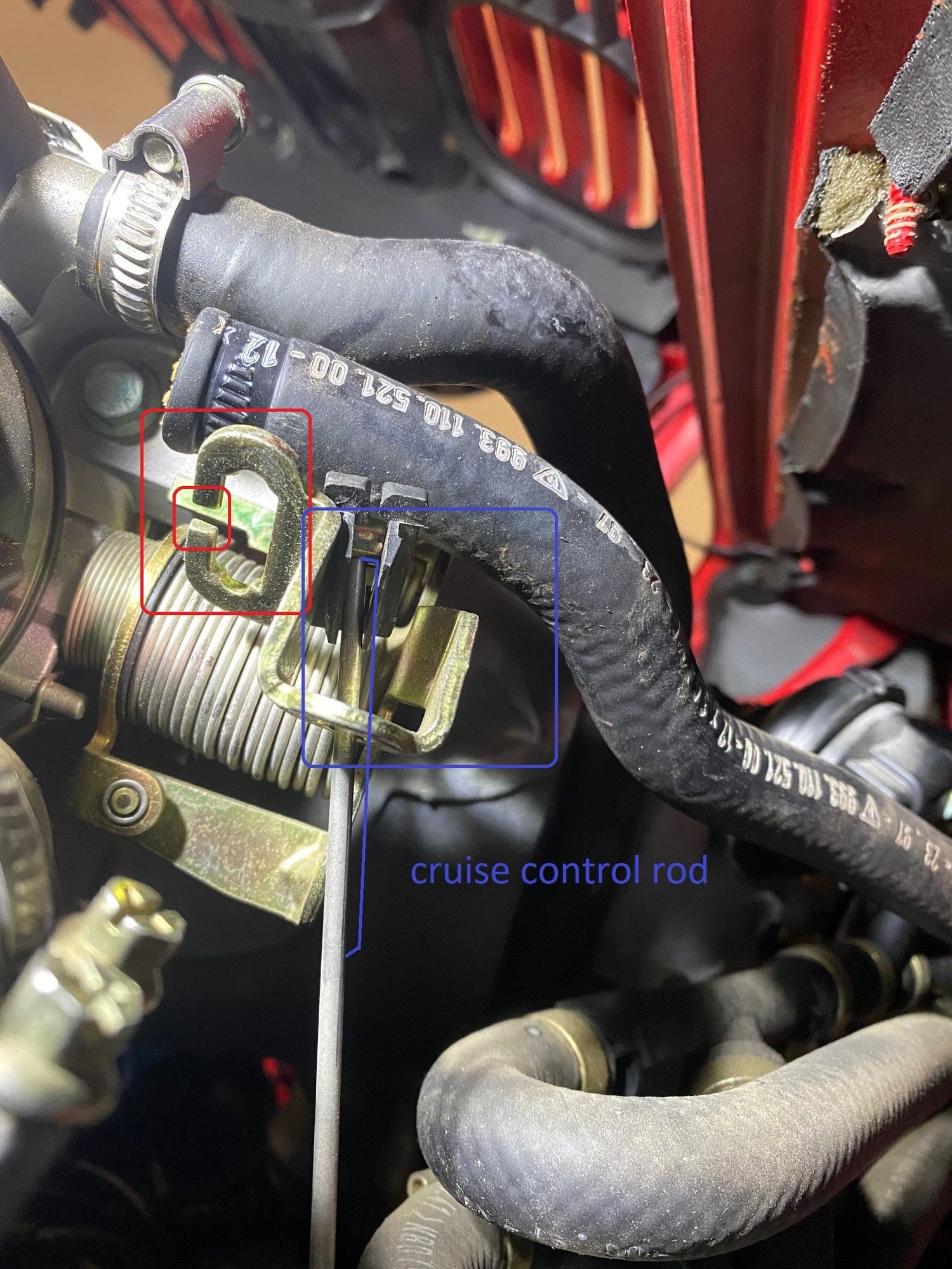
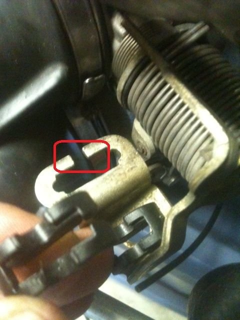
Let�s do the easier one first. Thanks to @swmic , there�s a trick to unhook the cruise control and it was a lot easier than I thought. As you can see in the picture, the top of the cruise control rod is connected to the throttle. The bottom is connected some type of mechanism sitting underneath the manifold. You can clearly see this when you look underneath the manifold.
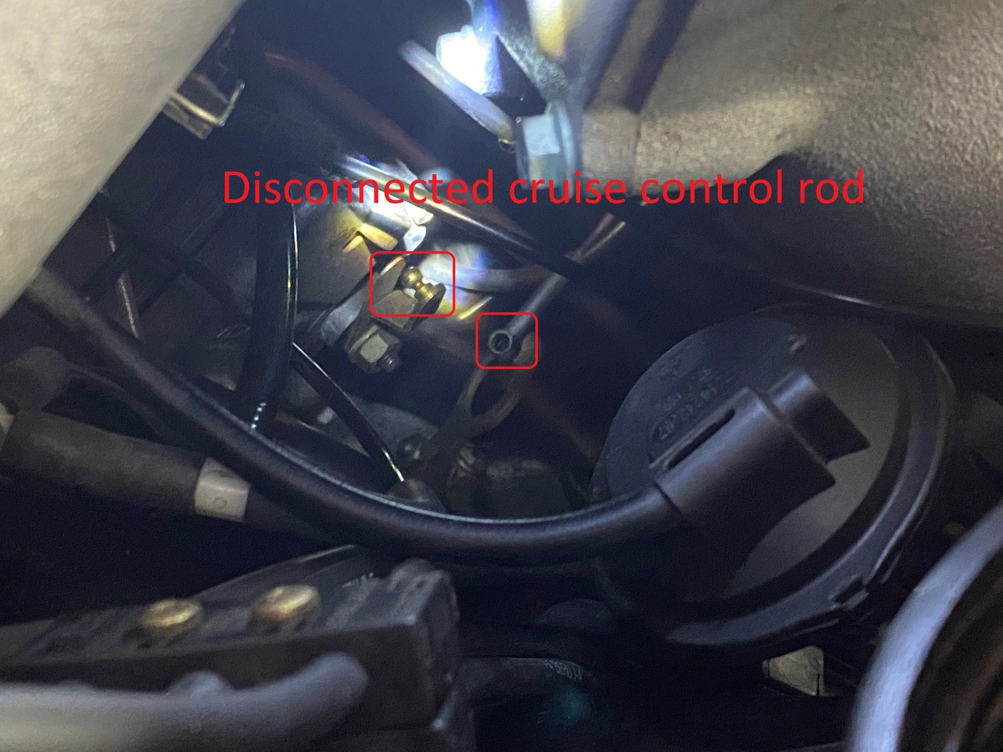
Here�s an up-close pic. All you have to do is pop the ball off to the left and now the cruise control rod is loose! Super easy. Do be careful not to bend the rod as you take off and move the manifold
Now the hard part. The following tricks are 100% @swmic so all credit due to him. I think it�s best to tackle this in three parts (or two if you�re successful)
Overview, you will need to unhook both A and B.
First is to release the cable on the top of the throttle (labeled �A�). The easiest way to do this is to release the tension on the throttle cable by pushing the throttle toward the front of the car.
On top of the manifold is this line that I disconnected b/c it allowed me to see the throttle and what I was doing a little better.
Once you move it out of the way, you can see the throttle in the back
@swmic used a long screwdriver to push the throttle (toward the front of the car) and with his right hand, he was able to unhook the top of the throttle. For once, my non-popeye forearms came in handy and I was able to get both left and right arms behind the manifold (basically hugging it) and it was super easy to release it after that.
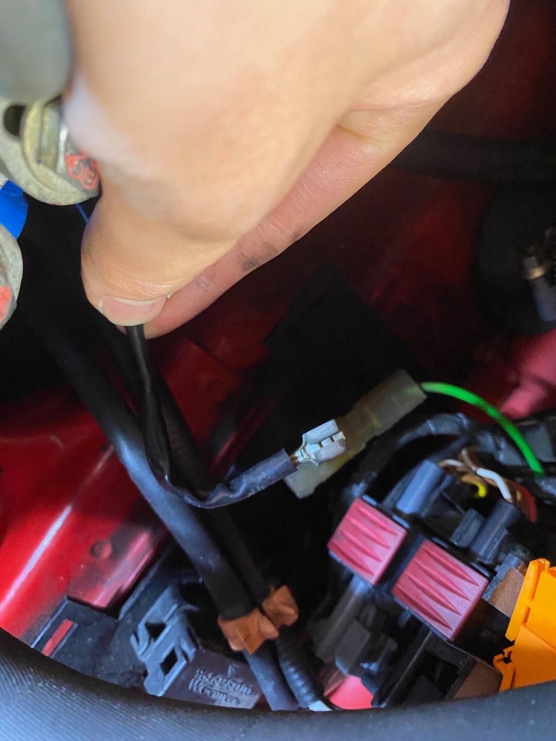
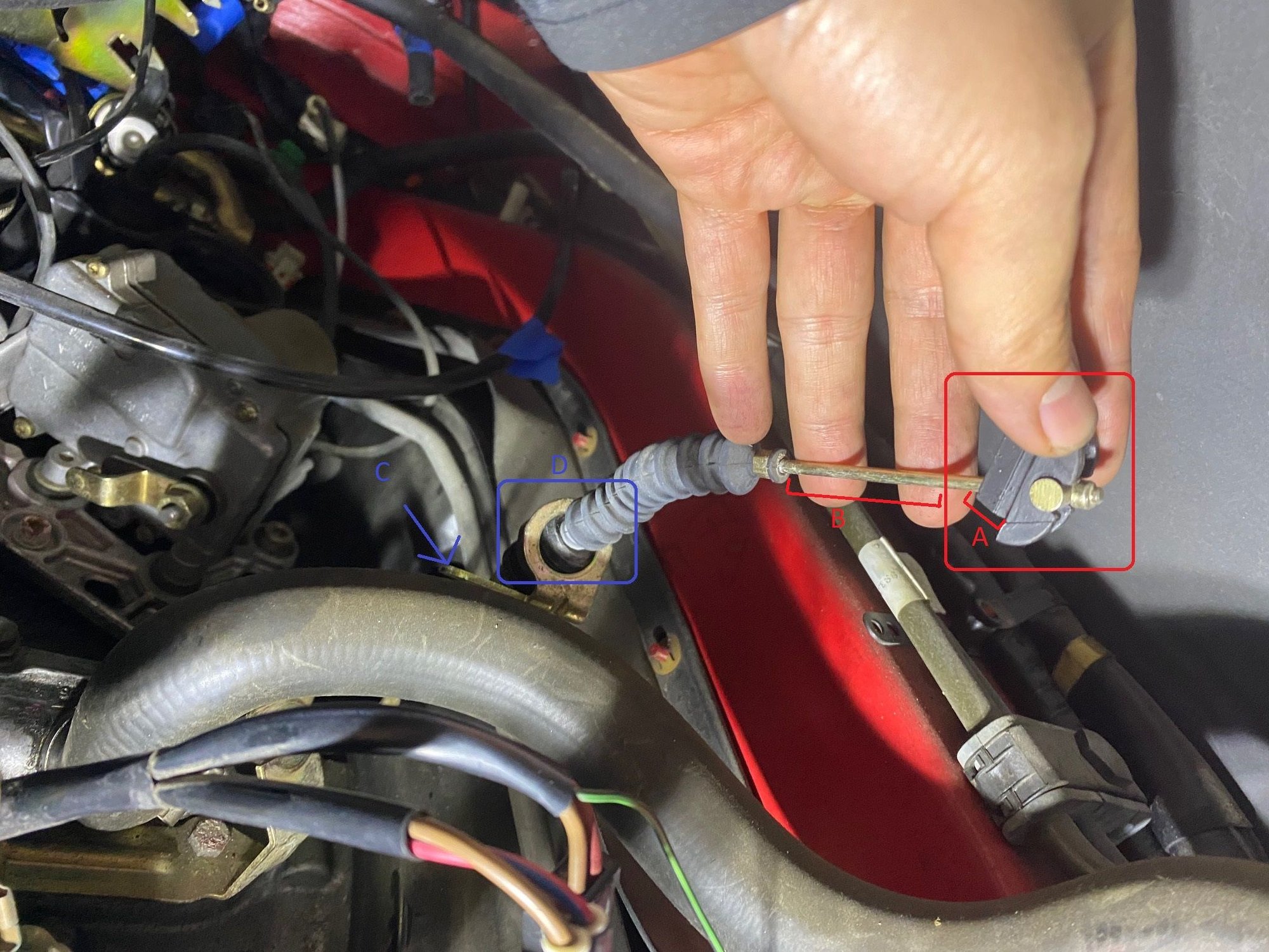
This is the general areas where I stuck my hand. Remember to take your time and don�t force anything.
Once you get your hand back there, you will feel for the bottom of the black base (A) and push up so it pops out of the throttle. With you pushing the throttle, there should be no tension and should be really easy to come out. Once you pop off the black base, there is a slit on the throttle that you can slip the throttle cable out (section B) off. This is all by feel b/c it�s pretty hard to see but if you see these pictures, you can visualize what to do.
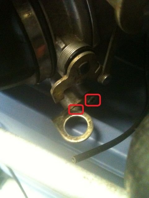
All good so far� not too bad� until now. The lower throttle cable is still attached to the manifold. @SWMIC had a very good idea� unbolt the lower bracket (�C�) off the manifold. It�s held on by two T30 screws. I was able to get one off but I couldn�t get the other one b/c the rubber grommet on the bottom of the throttle cable was in the way. If you are able to get the bracket off, that is the way to go. Once again, this is done by feel (be careful not to drop any tools).
I ended up having to push the rubber grommet down off of the bracket to fully release the cable. The easy part was releasing the rubber grommet, that incredibly hard part is putting it back on. Here�s a pic of it out.
With the throttle cable and cruise control rod released, you can now move out the intake manifold.
As I mentioned, there was one line on the driver-side that I decided not to take off, this is what mine looked like
So yes, even with a 1.5� engine drop, that�s enough to take out the manifold! As everyone says, put something in the six engine openings. I used crumpled up pieces of paper.
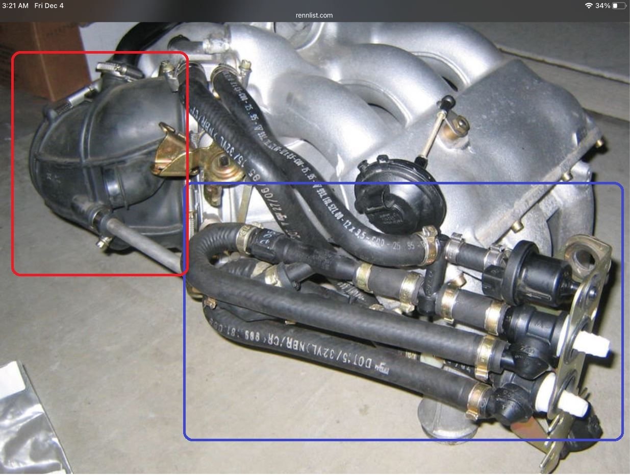
Here�s a pic of the intake manifold I found on RL. Once again, not sure who took this pic but credit to him/her
So once you move the intake manifold out of the way, disconnect the pipe connecting the SAI pump to the check valve
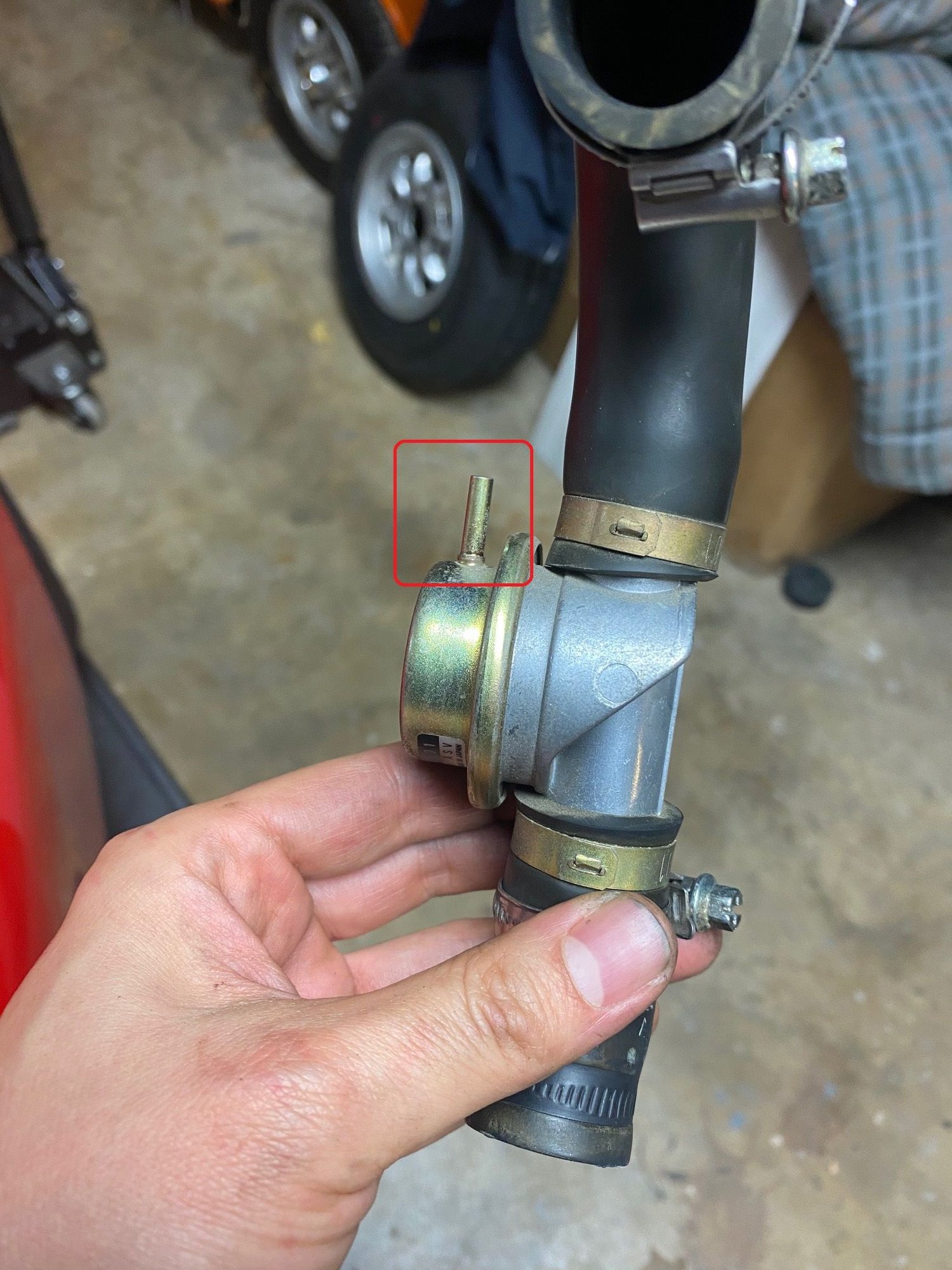
Note that there’s a vacuum line that connects to the shut off valve. Don’t forget to plug this back in during re-installation.
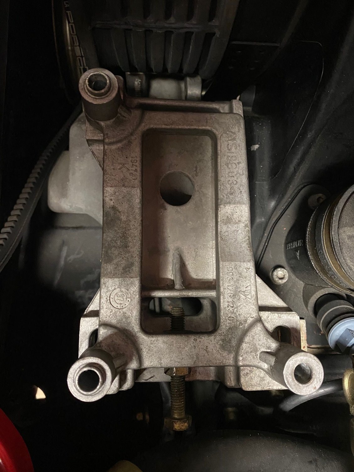
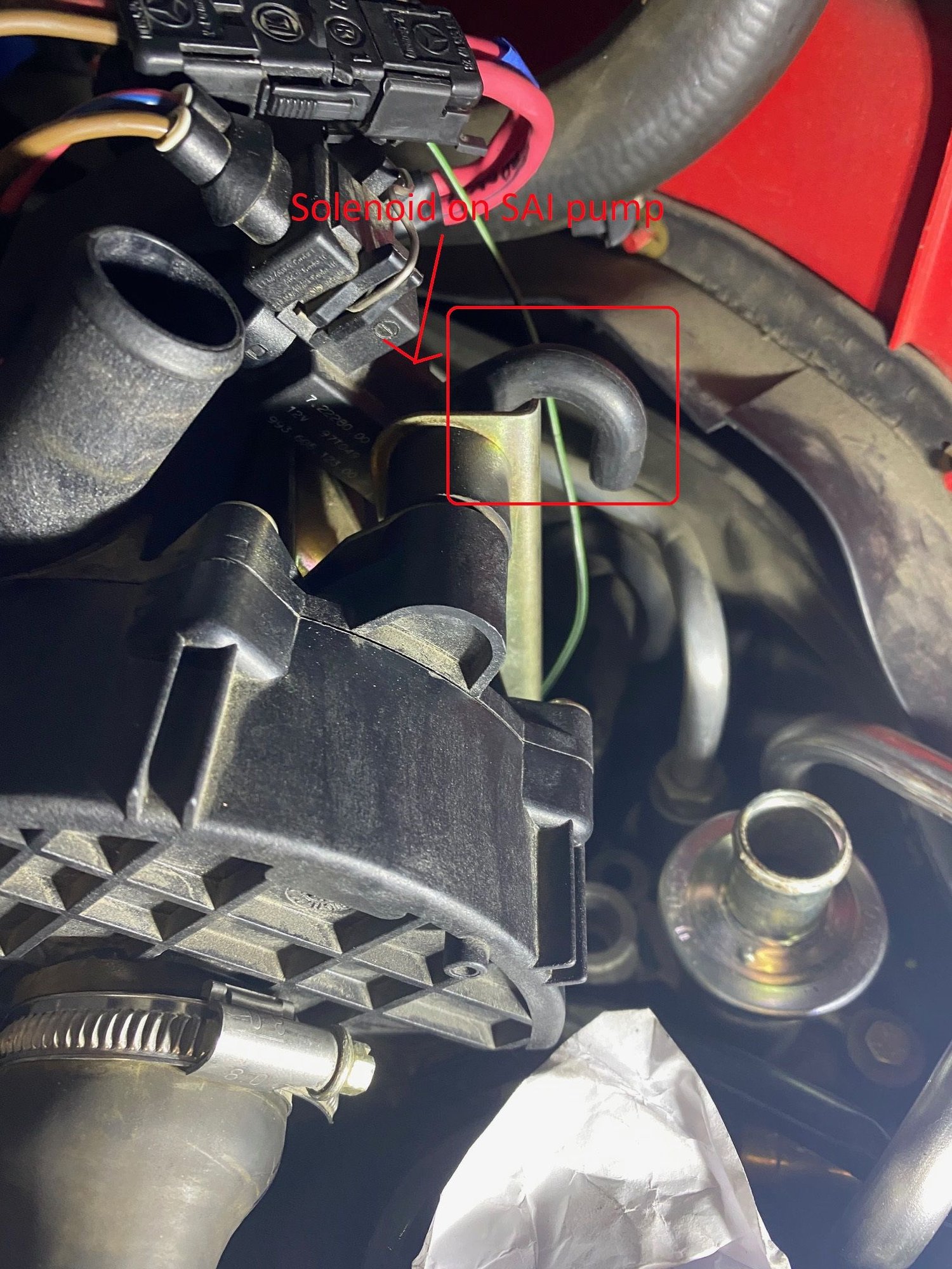
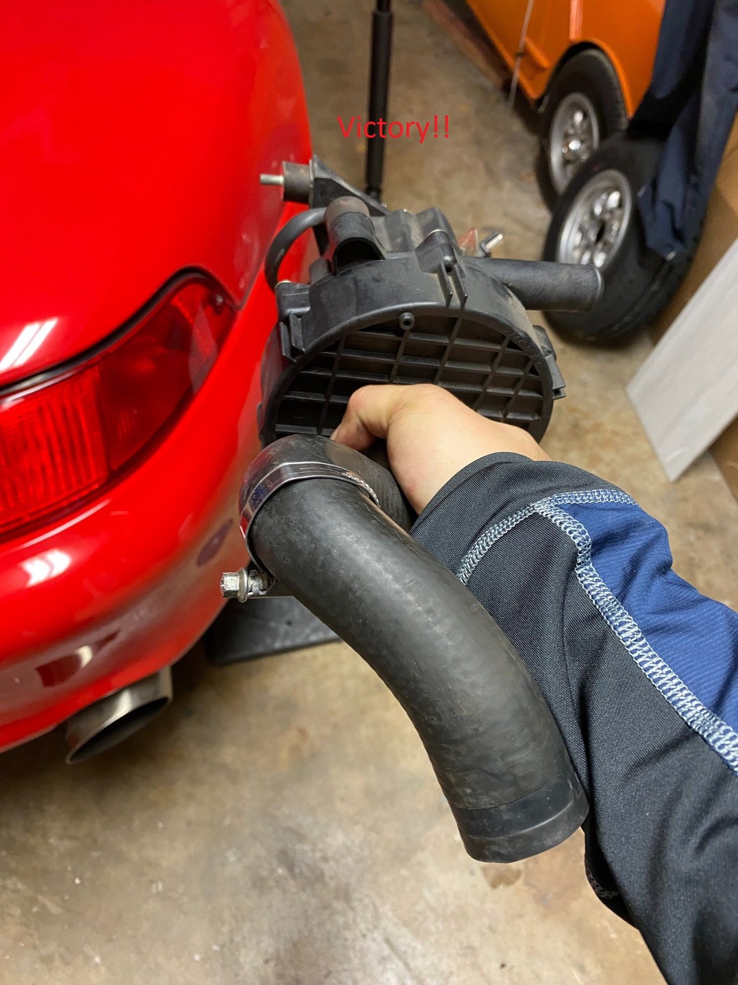
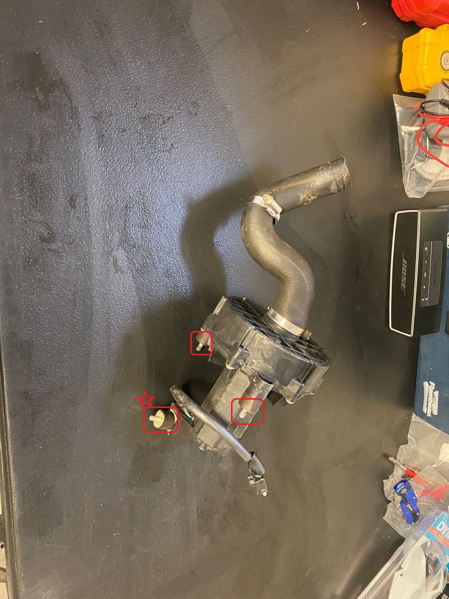
Next, disconnect the plug for the SAI pump, remove 4 10mm bolts holding the pump to the bracket and viola! Victory!
Here’s another view of where the 4 10mm bolts are. The pic only shows three (b/c one is not shown in the pics) but the one that’s starred was a surprise as I thought there were only three.
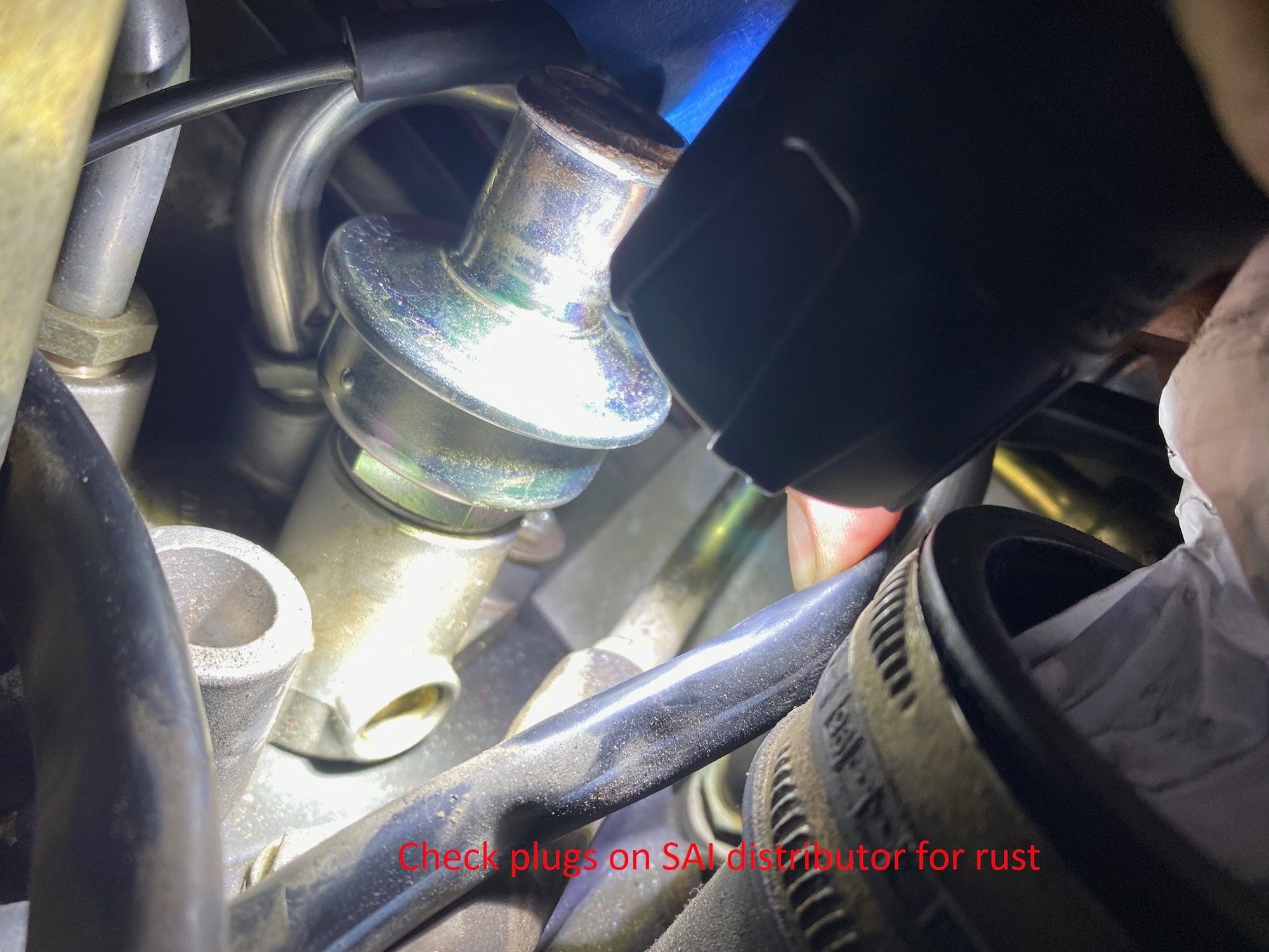
This is a bad pic but while you’re there, check the plugs on the SAI distributor to make sure none are rusted. If they are, now’s a great time to replace them
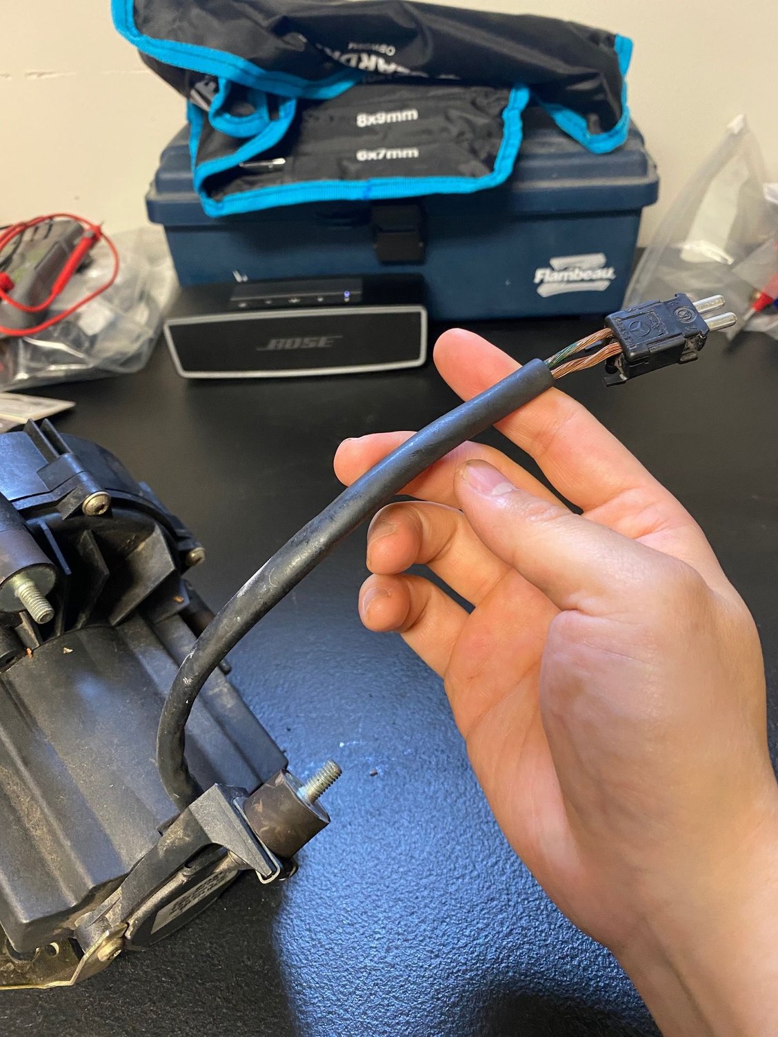
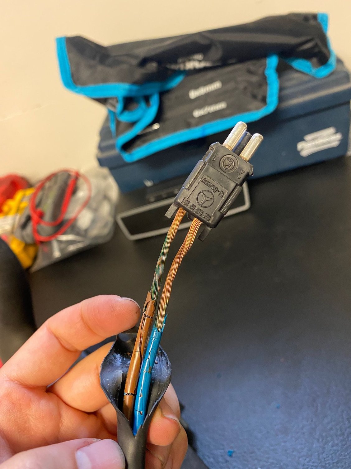
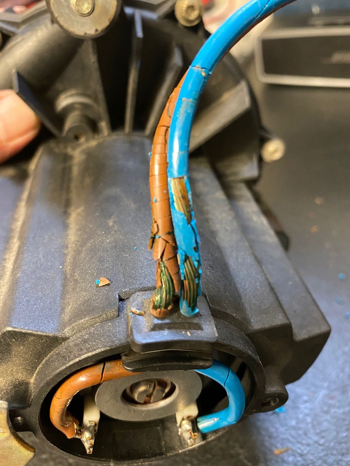
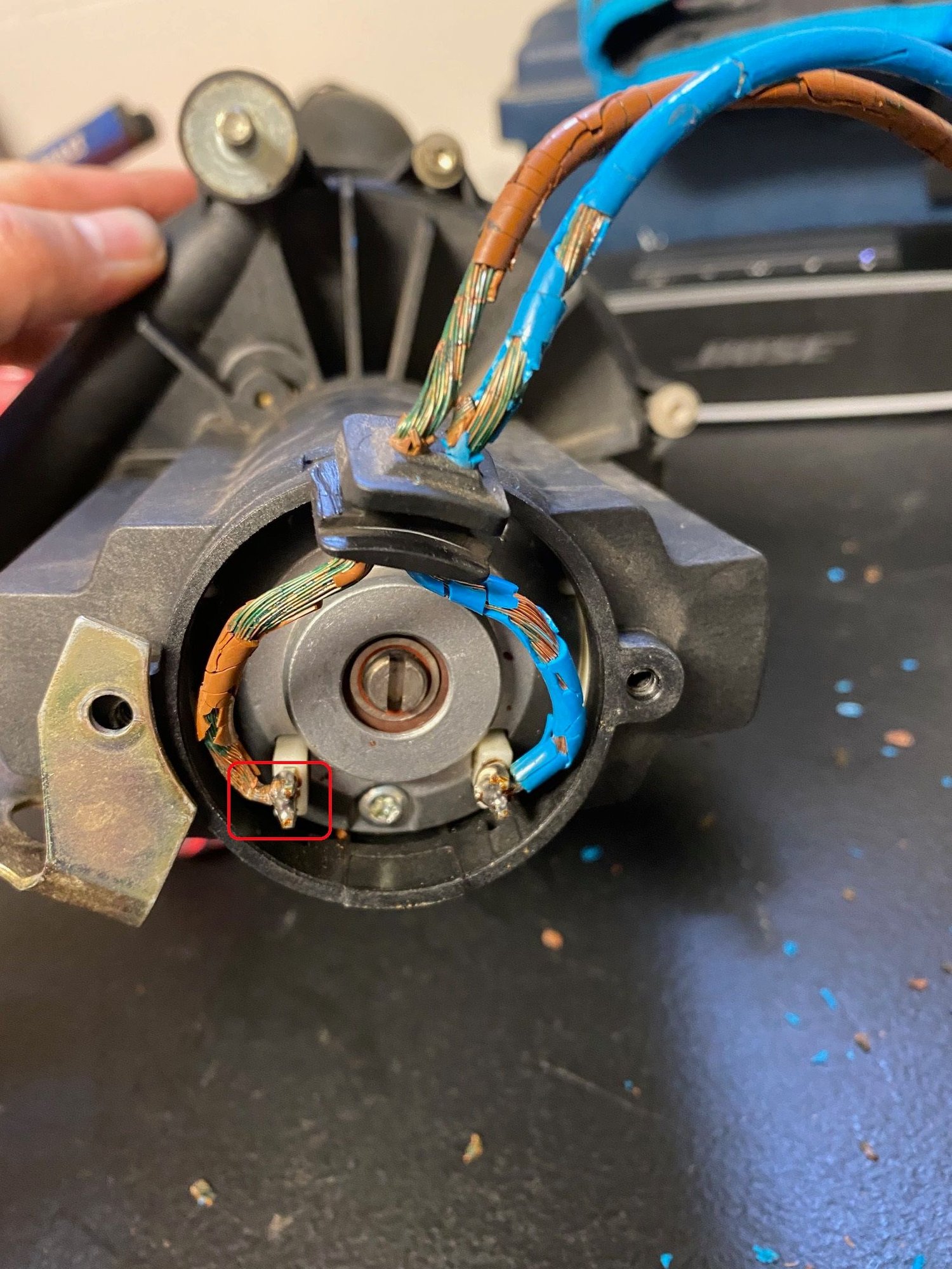
Here are a few pics of how badly the coating on the wires have deteriorated. Also, I noticed after I popped off the back of the pump that the brown wire wasn’t full soldered on and was loose. I think it was that and a combination of the exposed wires basically touching each other was creating a voltage draw and not allowing the pump to operating effectively.
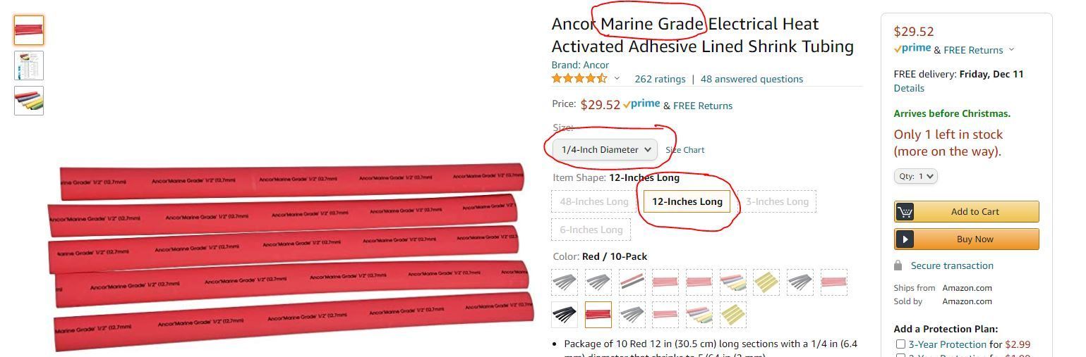
I purchased a set of marine grade shrink tubing (make sure you get �” diameter and 12” length) off Amazon
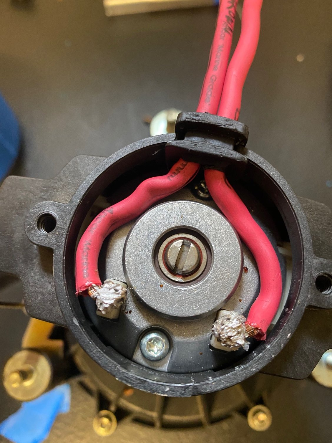
Completely took off the wires, stripped the old wiring off and re-did it. Goes without saying to make sure the wires are in the correct terminals on both the motor and the plug (brown is ground, blue is live)
Here are the steps from the shop manual. As you can see, I deviated from some of it (esp the throttle and cruise control cable part).
Reinstall should be pretty simple. Take your time. Make sure you do not pull hard on the throttle cable.
The End.
I hope someone finds this helpful and informative. I know I'm missing a few folks but thanks again to everyone who helped me with this DIY ( @pp000830 , @bobt993 , @Churchill , @ToSi , @XLR8 , @RobinSun, @AOW162435 and last but not least, to @swmic .
I definitely would not have bought the 993 if it wasn’t for the RL family and us journeying together through our ownership. God bless!
subscribed. I'm exactly where you are right now with the airbox and blower motor removed due to a suspension upgrade. Maybe I should remove/change the SAI valve while i'm at it.
Wow, just wow, great writeup on what is a complex DIY with many opportunities to miss things during disassembly and reassembly.
Added to my personal library.
Many thanks,
Andy
Great write up Edwin! Thanks for taking the time to do this. I would suggest replacing the SAI pump wires and not just put heat shrink over them. With the insulation deteriorated, the copper wire can get very corroded.
Nice work and thank you for documenting this. This post is saved to my favorites for the time when I have to tackle a job like this. Again, thank you for taking the time. Cheers
A really great posting.
Something we will all need to address someday.
I was looking at your wire replacement
and the solder joints in the below image look a little cold, not heated through. Did you have problems getting the contacts hot enough? Did you use a 75 or 150 Watt soldering iron? https://cimg6.ibsrv.net/gimg/rennlis...1056e1c975.jpg
Andy
Hey Andy,
I'm by no means an expert at soldering so I'm sure it could be improved upon. Based on my Amazon purchase, it's a 60W soldering iron.
Wow, just wow, great writeup on what is a complex DIY with many opportunities to miss things during disassembly and reassembly.
Added to my personal library.
Many thanks,
Andy
Andy,
If you want, feel free to post this on your 993 blog. I know your site has been helpful to me so hope to return the favor somehow.

 12-07-2020, 06:48 PM


 . Seriously though, great effort and super writeup