When you click on links to various merchants on this site and make a purchase, this can result in this site earning a commission. Affiliate programs and affiliations include, but are not limited to, the eBay Partner Network.
Thanks for sharing, mad skills with vision, design, and tools. Paint booth setup is also first rate lots to see and learn from here. Great documentation, setting the bar high for DIY. The journey is as much a reward as the destination! Subscribed to see how it turns our. Rennline should take note ;-)
Looking at your spray booth, I come to only one conclusion: holy Dexter Batman! Looks great.
Originally Posted by Kein_Ersatz
Thanks for sharing, mad skills with vision, design, and tools. Paint booth setup is also first rate lots to see and learn from here. Great documentation, setting the bar high for DIY. The journey is as much a reward as the destination! Subscribed to see how it turns our. Rennline should take note ;-)
Originally Posted by 911PERVY
Genius, pure genius! Lets hope you dont need it but the spray booth could double up as your own ICU!
Thanks gents, the paint booth has been used almost daily for the past couple of weeks - it was worth the build effort!
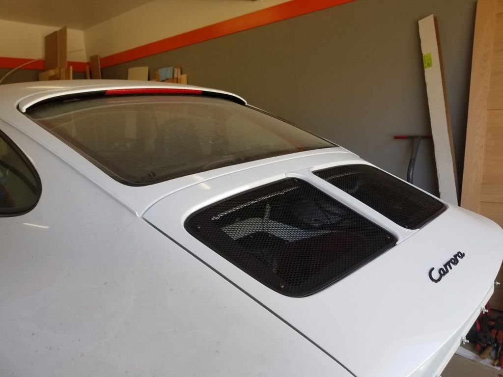
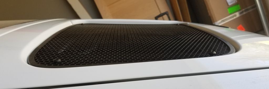
Time for an update. I wanted to get the two grills mounted (see original post) before finalising the bar design, just in case things were a couple of mm out. With the grills mounted, I started to measure.
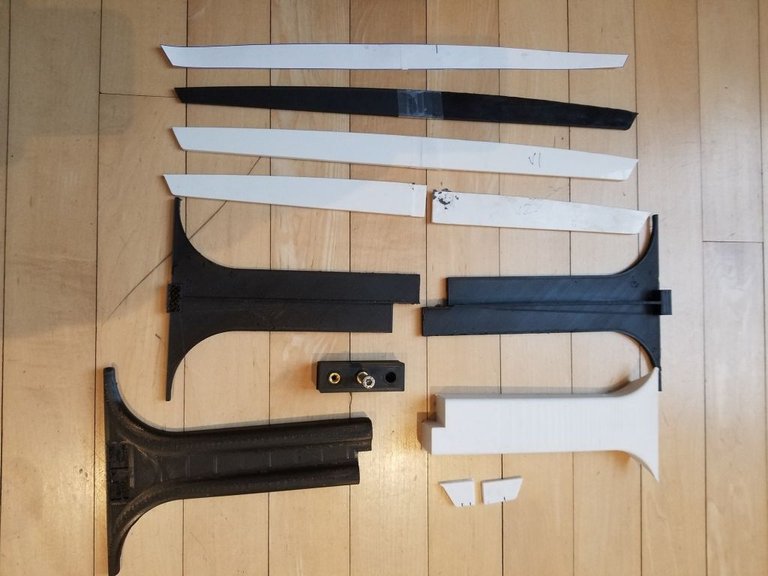
I made lots of paper and 3D printed test shapes, here are a few survivors:
Looking at the side profile, a straight line from the top edge to the bottom edge would be easy to design � but � the curve line shown is the curve of the engine lid if you project it from the top edge to the bottom. I did this with a piece of thin wood, held it tight top and bottom � allowing it to bow to follow the curve, and measured the curve offset from the straight line.
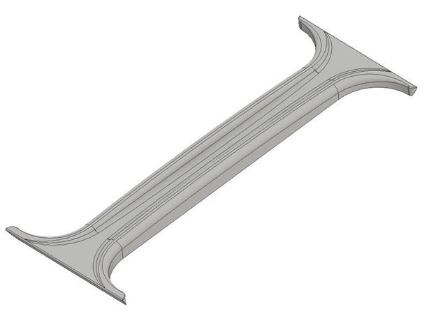
I ended up with this design:
2 red lines: The center face/valley floor traces a straight line from top edge to bottom. The sides curve up to follow the curve profile of the engine lid:
My 3D print envelope will not allow a 360mm long print � so the design was halved and holes added in the end faces to allow strengthening dowels to be inserted for when it was glued into one peice.
It was printed in my default material which is called T-Glase. This has strengths close to ABS (think Lego bricks) but is far easier to print with in terms of warping, adhesion etc. Printed T-Glase also (like ABS) is thermally stable at higher temps � some 3D print plastics are eaiser to print with but will warp when subjected to higher ambient heat i.e. above an engine on a hot day. T-Glase is also food safe so I can eat my dinner off the engine grill when done.
Mid-print below. You can see on the bottom left that the part is not �solid� � a mesh infill is being produced inside the �shell� of the part (top, bottom, sides) which on this were all: shell = 2.4mm thick. The mesh (infill) density for this was only 20%. I'm not a big man, but no way I could snap the below by hand, it is that strong when printed. It is rare to print solid (100% density) - I only do that below a certain object size where you do lose strength if not 100% density.
I printed using a 0.4mm diameter nozzle so the below took 15 hours. I usually print something like this with a 0.6 nozzle which could have taken only 6 hours (or 0.8 nozzle at 4 hours) but the layer �steps� on the finished part would be more pronounced (i.e. to print faster, put down thicker and wider layers).
You may also spot the text �3.6� cut into the right side. I was going to print extra numbers 3 and 6 approx 1.5mm thick, paint them black and glue then into the 3 and 6 indents (which would be painted body white). This was an idea that I eventually decided was not going to work (looked too fiddly?!?) and I filled it in.
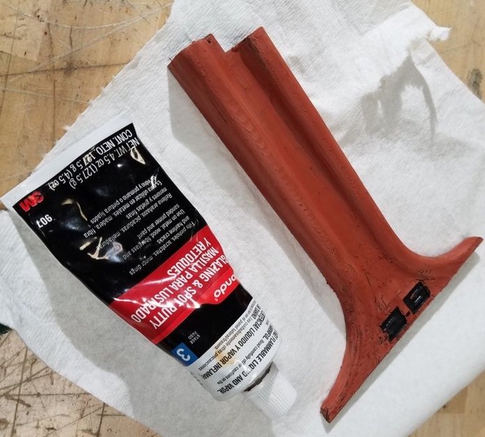
To blend the printed layer �steps� I then applied Bondo and gave the dried Bondo a rough sand:
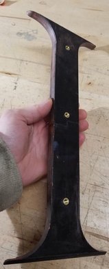
I then glued the two together, using standard 2 part epoxy but with metal dowels inserted and glued (M4 bolts with heads cut off...!) to strengthen the joint:
I added the 3 heat-certs (see post #13 above):
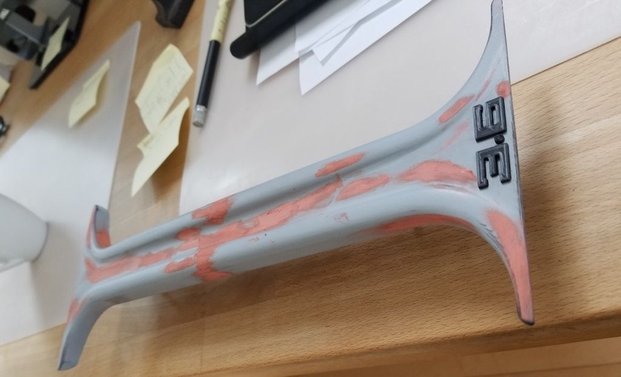
Then started the process of filling, sanding, priming (high build), filling sanding, priming:
Then I moved onto the final finish (after filling the �3.6� indents).
I used Automotivetouchup.com and purchased primer, basecoat (3AU Glacier) and top gloss lacquer. It was all supplied ready to spray. I used a HVLP (@30-35 Psi) for the primer and basecoat, then a standard spray gun (@25 Psi) for the lacquer. I seem to get better finishes for lacquer with a non-HVLP gun.
It took a couple of weeks until it looked ok. I need more practise with auto paints lol. Wet sanding with #800 gave me something that is a good 10 footer:
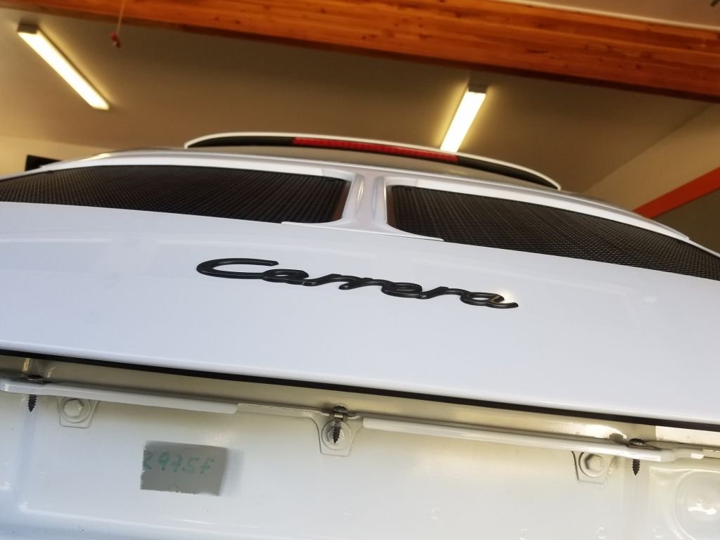
So next I drilled the 3 mounting holes in my alu baseplate (the end finish was not as neat, I had to slot slightly...):
3x M5 button heads later and - I�m happy for now.
Colour match is 96% (!) and I am not 100% sure of the contours I designed yet, but I will run it for a while and see:
"Half English hands" :-) Amazing project. It's really fun to follow along - thanks for sharing the pictures and the process.
Thanks a lot - it was fun to do, wish I could do this for a living but the time I take, this grill bar would cos the same if I cast it in gold.... lol.
Exceptional and meticulous effort put into all your work, and the results speak for themselves.
As someone who cannot 'create' stuff, only take it apart and put it back together, my hat is off to you!
Shame it is so labor intensive, as I'm sure many people would want a tailored split grill.
Thinking outside the box, and I apologize if you've said elsewhere, but did you consider using the existing spoiler and just making new half-grills and buy a standard center-bar?
If you could make the grills 'quickly' in a steel color, half of the 993 owners would want one from you.
Exceptional and meticulous effort put into all your work, and the results speak for themselves.
Thinking outside the box, and I apologize if you've said elsewhere, but did you consider using the existing spoiler and just making new half-grills and buy a standard center-bar?
If you could make the grills 'quickly' in a steel color, half of the 993 owners would want one from you.
Thanks a lot!
If I follow your idea ^ then no, I did not think of that! It is a cool idea.
My research showed if you want to remove the factory grill part (the black) to extract it from the body coloured spoiler surround = you are cutting glued joints. I suspect it would be the same for the 993 split grill.
One of my targets was zero cutting / hacking.
But if you are willing to cut - or buy another, your idea is great and would likely result in a more factory quality finish.
Another target I had was to remove the spoiler / motor etc completely. I converted the spoiler to manual years ago and very rarely raise it these days. So I was ready to ditch it. Doing this also gave more grill surface area.
You should have a go, maybe this is your moment to discover hidden DIY talents! Thanks again.
I did my own split-grill a few years ago - but I bought a second-hand pair of split-spoiler grills and centre-bar, and then a battered spoiler oval surround. I prepped the oval and centre, but had a pro-shop paint it Polar Silver.
Therefore there was no separating needed. To assemble it, I used factory fixings, and silicone as well, just in case as I do get up to 155mph - on a circuit of course.
Unless you need the money by selling the spoiler, why not try separating the grill from the oval?


 ):
):