
Cayman S Clubsport???
 06-11-2009, 12:05 PM
#31
Rennlist Member
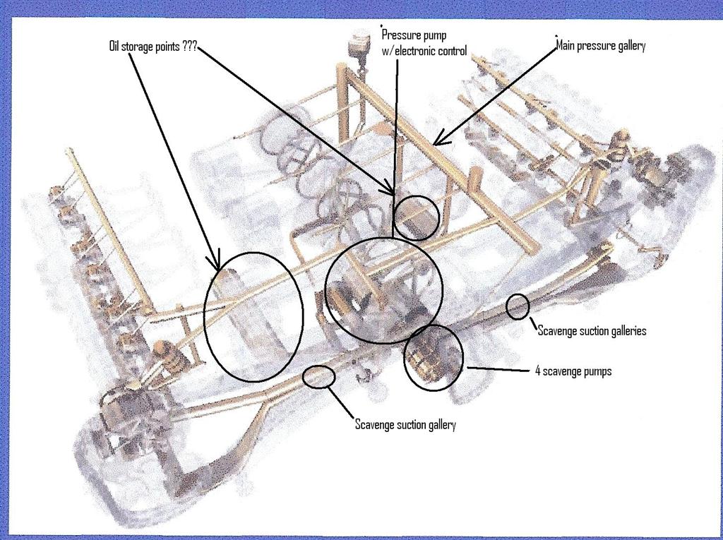
Below is an annotated by me phantom diagram of the A91 oiling system. The "Oil Storage Points???" references are to the air-oil separators discussed earlier here.
Note the 4 stage scavenge pumps drain the lower camshaft areas of the cylinder heads through 4 long oil "Scavenge Suction Galleries". One pump is dedicated to the forward and backward section of each cylinder head for a total of 4 pumps for the 2 heads.
The existing pump would have to be modified such that at least one pumping section was added (total of 6 sections of pump) to pump oil from the bottom of the crankcase to an external tank and to feed oil from the tank to the pressure pump section of the existing pump. The scavenge pumps would also have to have their output directed toward the tank. Fittings for these purposes could be cast into a new crankcase cover.
Below is a comparison of the GT3 oil pump to the 964 Carrera oil pump. The GT3 pump will fit into an air-cooled crankcase since of course the GT3 uses the air-cooled crankcase. Note the GT3 pump has divided the one large scavenge pump to two scavenge pumps. I just used one of these GT3 pumps in an engine I just finished and it was installed in a crankcase from 1965!!.
In addition to the pump shown, the GT3 has a separate pump for each cylinder head that is driven from an exhaust camshaft. These pumps send their oil directly to the oil collection tank. There is a total of 4 scavenge pumps in a 996 & 997 GT3 engine.
 06-11-2009, 07:30 PM
#32

Does the existing pump (9A1) have enough capacity to be divided into 6 sections of pump? Do you think it's better to modify rather than buying an aftermarket pump?
I don't know if you're aware but the pressure side of the 9A1 pump is variable-type (on-demand, electronically controlled). Do you think the pump should still be variable-type for dry sump? By comparison, I think the GT3 pump is non-variable.
The scavenge suction galleries shown in the pic are integrated, aren't they? Should those still be used rather than external plumbing? What additional lines would be required? Ideally, external plumbing should be kept as minimum as possible, shouldn't it? Does the Cayman have an oil cooler (radiator) and if so, where is it located?
06-11-2009, 08:00 PM
#33
Rennlist Member
I am just speculating in all this anyway, but I don't think it would be easy to modify the existing pump. I know that the pressures side of the pump is variable output to conserve horsepower, this could be eliminated in a new design. The Gt3 is non-variable.
The scavenge pump galleries are integrated into the engine's castings. The engine has an oil-water heat exchanger mounted on the top of the engine next to oil filter.
Theoretically, if a new pump and bottom cover for the engine were designed together, the only external lines required would be to and from the external oil tank, just like an air-cooled 911 engine.
Below is picture of drive chain and pump from parts book:
06-12-2009, 06:48 PM
#34

Fittings for these purposes could be cast into a new crankcase cover.
The (existing) scavenge pumps would also have to have their output directed toward the tank..
NEW EXTERNAL PUMP AND SUMP
I think the new sump pan should have 2 (or even 3) scavenge galleries. Here are some examples, for ideas:
http://www.daileyengineering.com/oilpans.htm
http://www.drysump.com/
A challenge would be to find a way to drive the external pump. Belt driven? From where? Any ideas?
By the way, click the following link, then "click Engine diagram" and place your cursor over items number 1 and 18. Any idea what these two items are?
http://www.porsche.com/uk/models/cay...ndetail/drive/
06-17-2009, 01:12 AM
#35
Rennlist Member
As you have noted at those sites that specialize in dry sumping other engines, it would be possible to do it on the Cayman.
I am sure it will happen either from inside Porsche or the aftermarket at some point.
In the engine diagram at the Porsche site #1 the high pressure pump is for the DFI and #18 the vacuum pump is to supply vacuum to vacuum powered devices such as the power brake booster and the HVAC controls.
I am sure it will happen either from inside Porsche or the aftermarket at some point.
In the engine diagram at the Porsche site #1 the high pressure pump is for the DFI and #18 the vacuum pump is to supply vacuum to vacuum powered devices such as the power brake booster and the HVAC controls.