
Wiring diagram for 14-pin connector in passenger footwell?
 01-14-2013 | 01:31 PM
#1
Thread Starter
Burning Brakes
Joined: Mar 2011
Posts: 1,219
Likes: 21
From: Austin, TX
Could someone point me to the section of the wiring diagrams in the manual that shows the 14-pin connector located in the passenger footwell, the wires of which go into the harness and then into the DME? This connector's cap broke during my project, so I had to put the wires back in based on my best guess of where they fit in the sockets of the connector, on my back, at a very uncomfortable angle, so I think there's a high likelihood that I didn't get them all in their correct sockets, and that this may be behind why my DME doesn't seem to be sending a signal to my car's ignition system to throw a spark. Or if anyone has any other way (some very clear pictures, a wire-by-wire description of which wires go into which sockets, etc.) of helping me confirm how this connector is supposed to be wired, I would be extremely grateful. Thanks.
01-19-2013 | 01:55 PM
#3
Thread Starter
Burning Brakes
Joined: Mar 2011
Posts: 1,219
Likes: 21
From: Austin, TX
I don't have a picture of it, but it's the only 14-pin connector in the passenger footwell. One end of it leads to the DME, the other to a bundle of wires that go up under the dash. And I found the wiring diagram for it.
A major word of caution with this thing - when taking it apart, DO NOT remove either of the caps, as this will cause the wires to pop out, leaving you with a major headache. Just wedge the blade of a screwdriver between the two halves of the connector, gently twist, and separate the two halves.
A major word of caution with this thing - when taking it apart, DO NOT remove either of the caps, as this will cause the wires to pop out, leaving you with a major headache. Just wedge the blade of a screwdriver between the two halves of the connector, gently twist, and separate the two halves.
01-19-2013 | 05:56 PM
#5
Thread Starter
Burning Brakes
Joined: Mar 2011
Posts: 1,219
Likes: 21
From: Austin, TX
Gene,
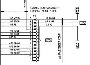
Have you taken your harness out yet? If so, could you do me a huge favor and put the two halves of the passenger footwell 14-pin connector up against each other, like this:
Attachment 696489
and tell me if what you have looks like what I have pictured? In mine, three of the connector pairs (numbers 2, 5, and 13) don't have mates, meaning that three of the wires one the DME side of the 14-pin connector (the side that contains the wires with the male bullet connectors) are kind of flopping the the breeze inside the connector, which seems very strange. Thanks!
Last edited by Cloud9...68; 01-22-2013 at 09:27 PM.
01-19-2013 | 06:50 PM
#6
Racer
Joined: May 2011
Posts: 364
Likes: 1
It's curious that you have one flipped exactly - both horizontally and vertically... Are you sure you read the wiring diagrams correctly, because if you turned the male half 180 degrees you can see the pins would match positions perfectly and all the numbers would match, but of course the halves would not mate.
Trending Topics
01-20-2013 | 01:54 AM
#9
Thread Starter
Burning Brakes
Joined: Mar 2011
Posts: 1,219
Likes: 21
From: Austin, TX
I'm convinced the male piece that the bullet connectors press through is wrong - note that the part numbers for the two halves are the same - they should have different part numbers to reflect the fact that they should be mirror images, and not be identical to each other. No idea how I ended up with a set-up like this. Maybe I ordered a new one somewhere along the line, and either ordered or received the wrong one.
01-20-2013 | 04:44 AM
#10
Three Wheelin'
Joined: Mar 2009
Posts: 1,544
Likes: 4
From: Brisbane, Australia
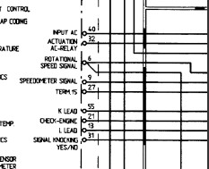
The connections are shown in the FWSM wiring diagrams:
Pins 9, 14 and 1 (on the socket side) are not used
Pin 13 is used for knock counting diagnostics (hence not connected to the other side)
Pin 2 is for RPM
etc....
Pins 9, 14 and 1 (on the socket side) are not used
Pin 13 is used for knock counting diagnostics (hence not connected to the other side)
Pin 2 is for RPM
etc....
01-20-2013 | 01:28 PM
#11
Thread Starter
Burning Brakes
Joined: Mar 2011
Posts: 1,219
Likes: 21
From: Austin, TX
Thanks. Yes, I've been using the wiring diagram, and am as sure as I can be that I have it wired correctly now. Still nothing coming out of the DME, though. Blink test doesn't work (CEL illuminates, but doesn't blink when I push the throttle to the floor with the key in the start position), and there's no voltage at the pin (87b) of the DME relay that energizes the fuel pump, and of course there's no spark as well. I guess the next step is to try replacing the DME itself (no idea why it would have died just sitting in the passenger footwell for nearly two years, though...)