

Torque tube rebuild pics / video
 05-26-2017, 06:16 AM
#1
Three Wheelin'
Thread Starter
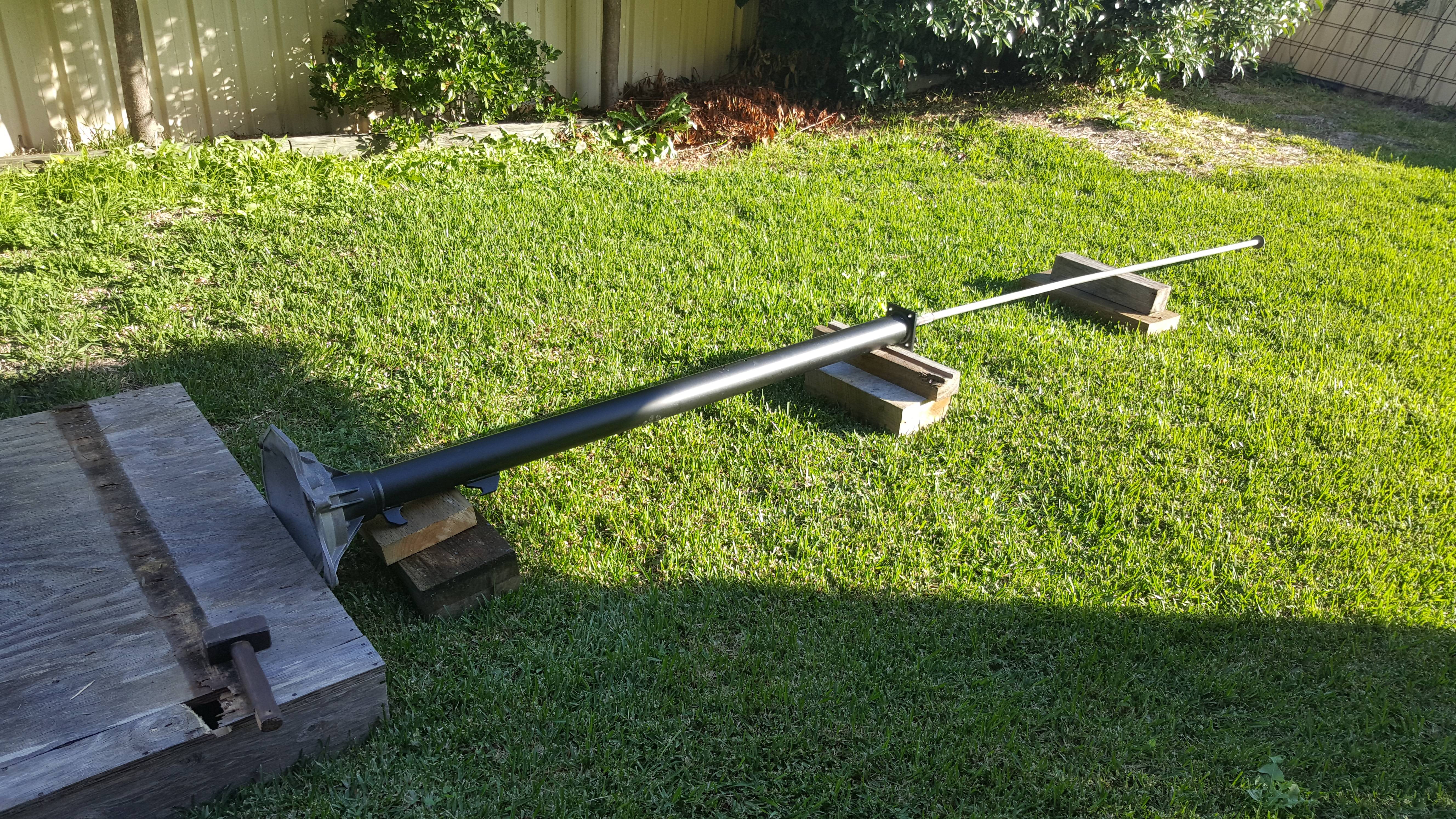
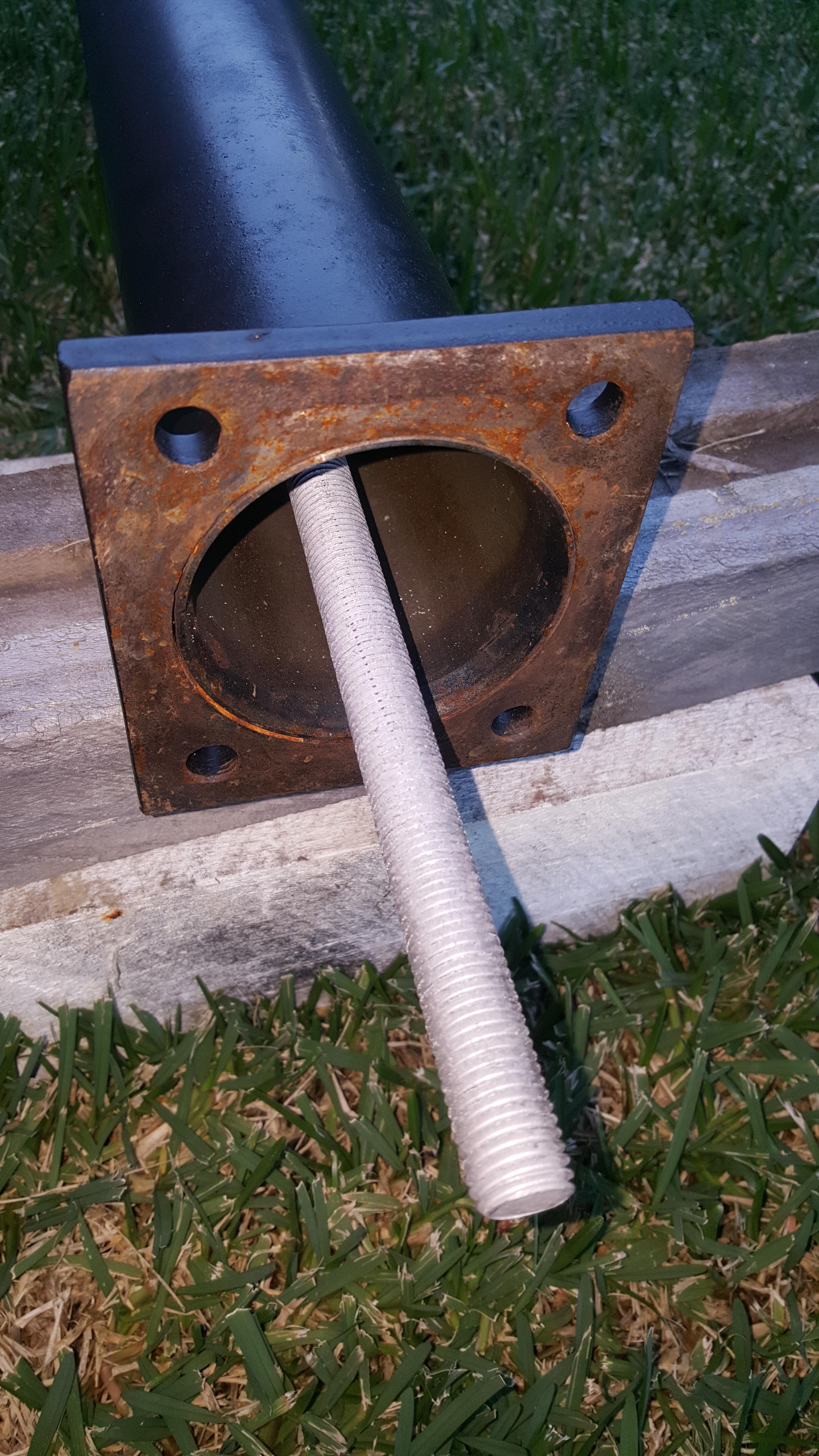
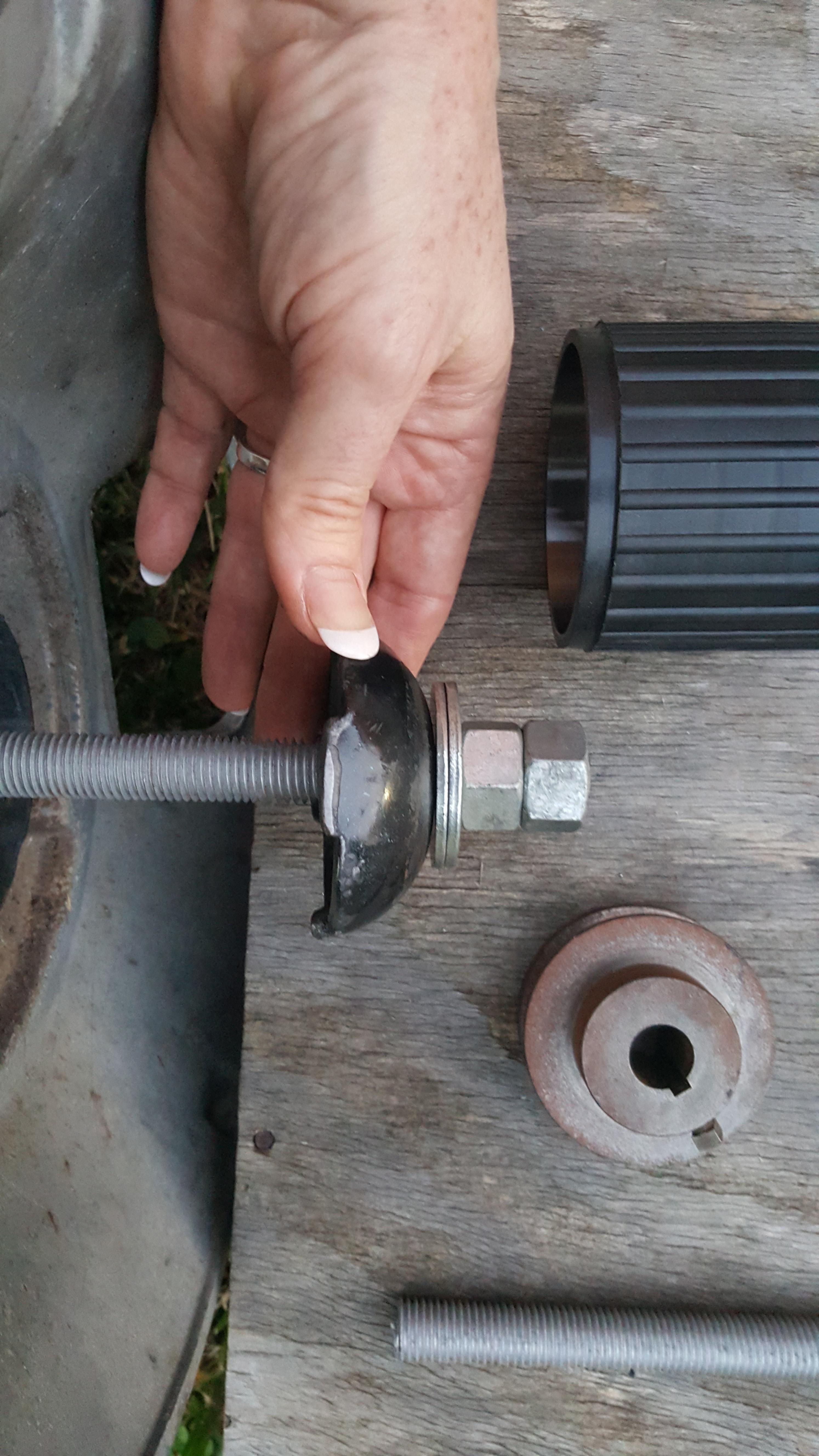
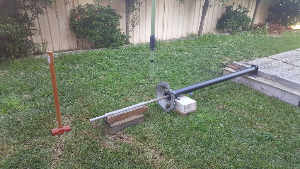
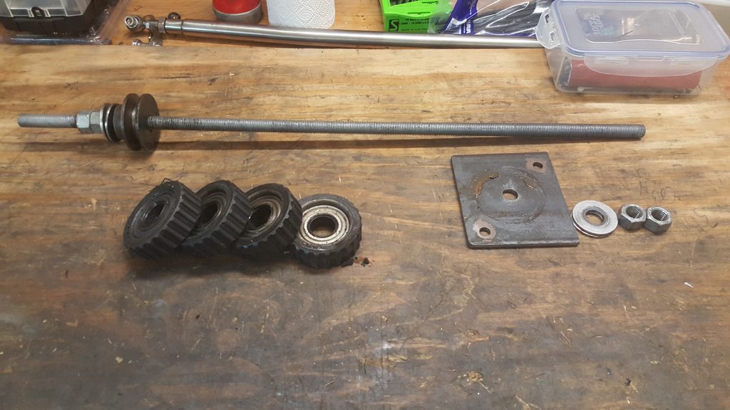
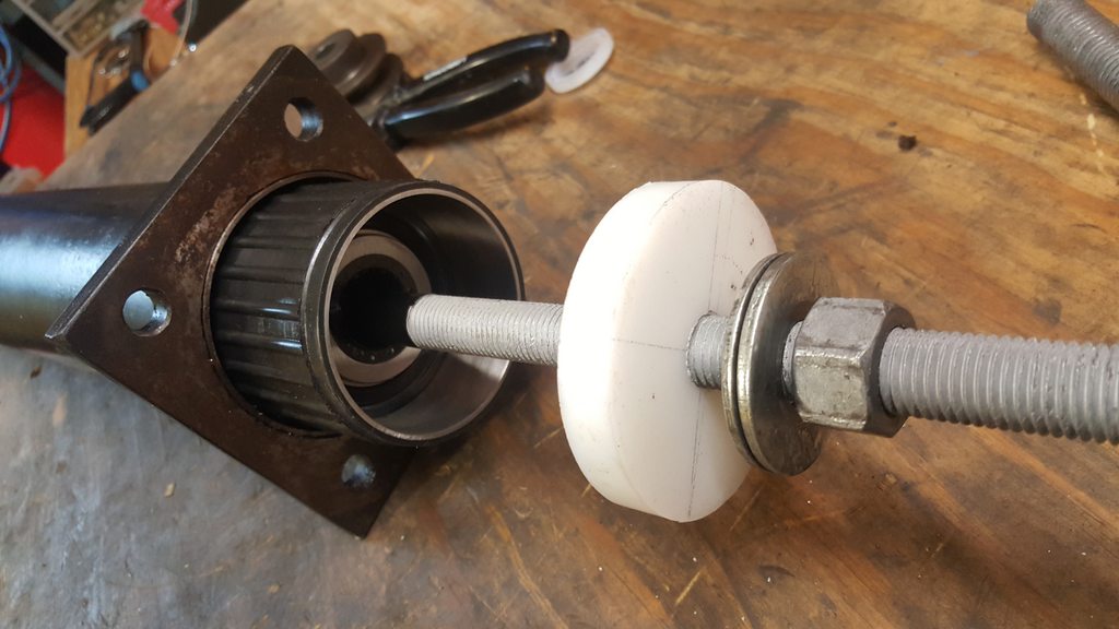
Got started on my torque tube rebuild this afternoon. Drive shaft removal went smoothly using a length of 1/2" ID thick walled galvanised pipe. Then I rigged up an extraction tool based on the Clarks Garage approach. The only tricky part of that was finding something to use for the round extraction piece which is sturdy and a close fit to the internal diameter of the Torque tube/bearings. I found a pulley which was a bit small so I ended up using the cup from a trolley jack - I just had to grind some metal away and drill a hole for the m16 threaded rod to pass through.
I ran out of light so I'll pull the bearings through tomorrow.
I ran out of light so I'll pull the bearings through tomorrow.
 05-28-2017, 11:46 PM
#3
Three Wheelin'
Thread Starter
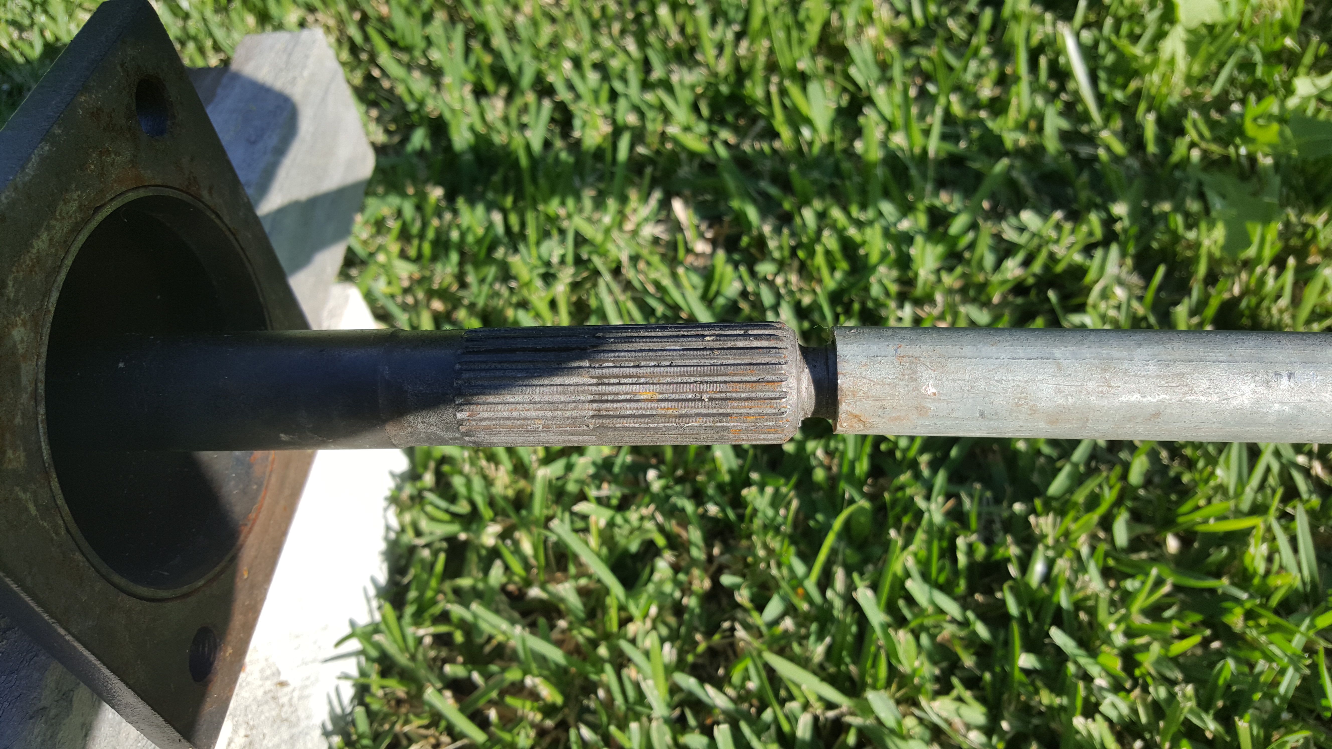
Constantine provides measurements but if you look at the drive shaft on one of the pics above the bearing marks are quite evident and easily measured.
As for the extraction it got a bit more complicated than planned!
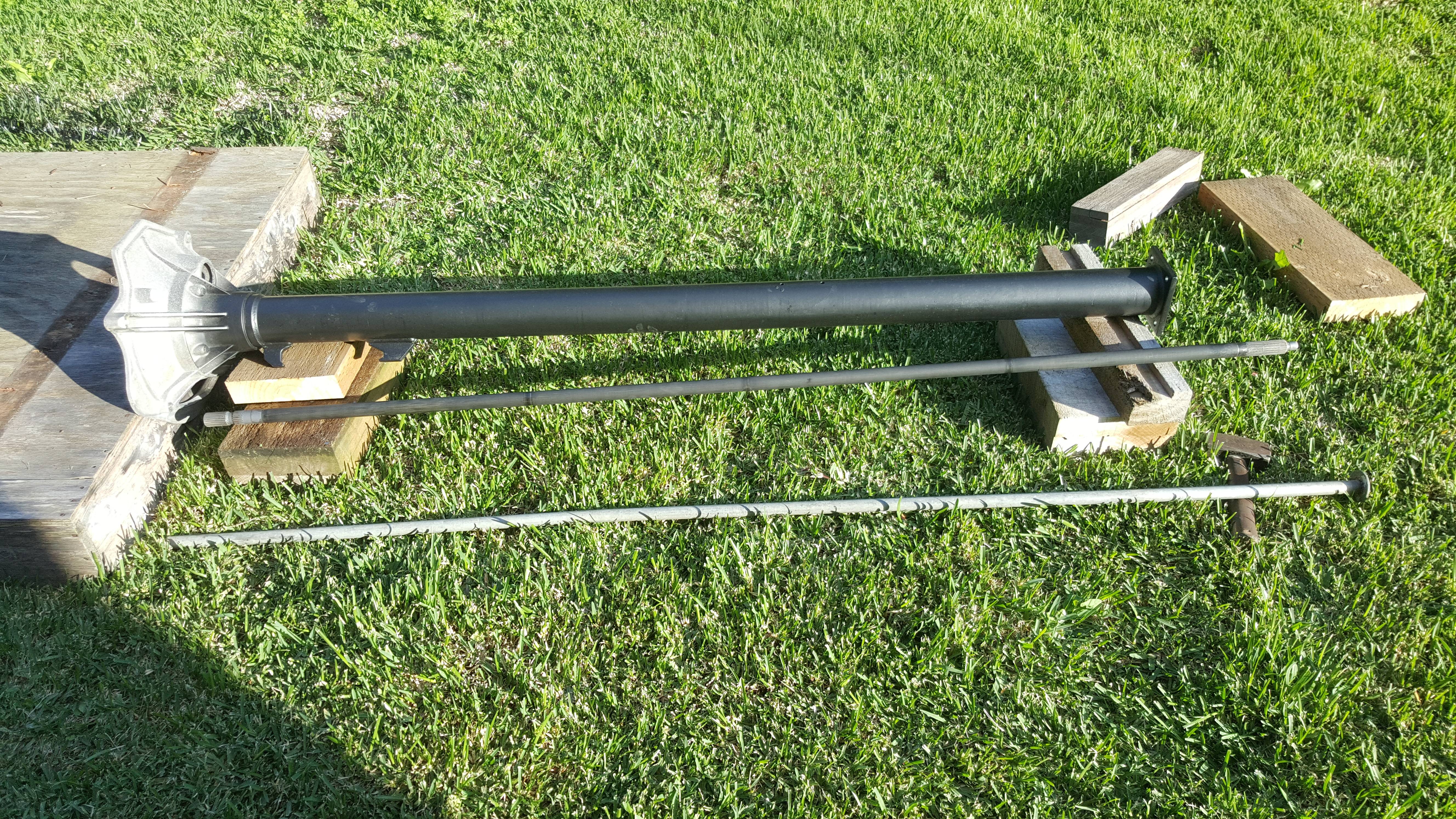
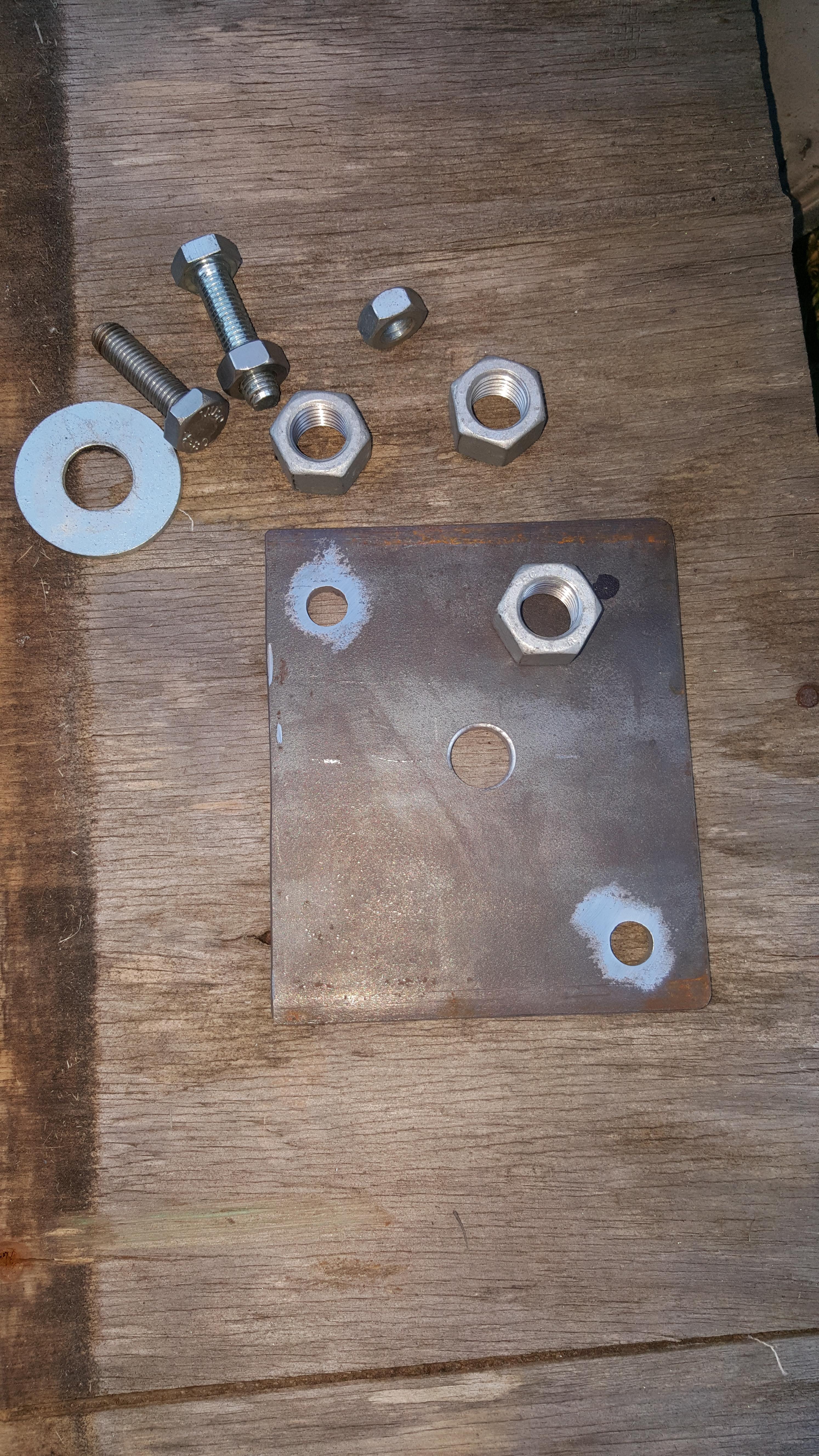
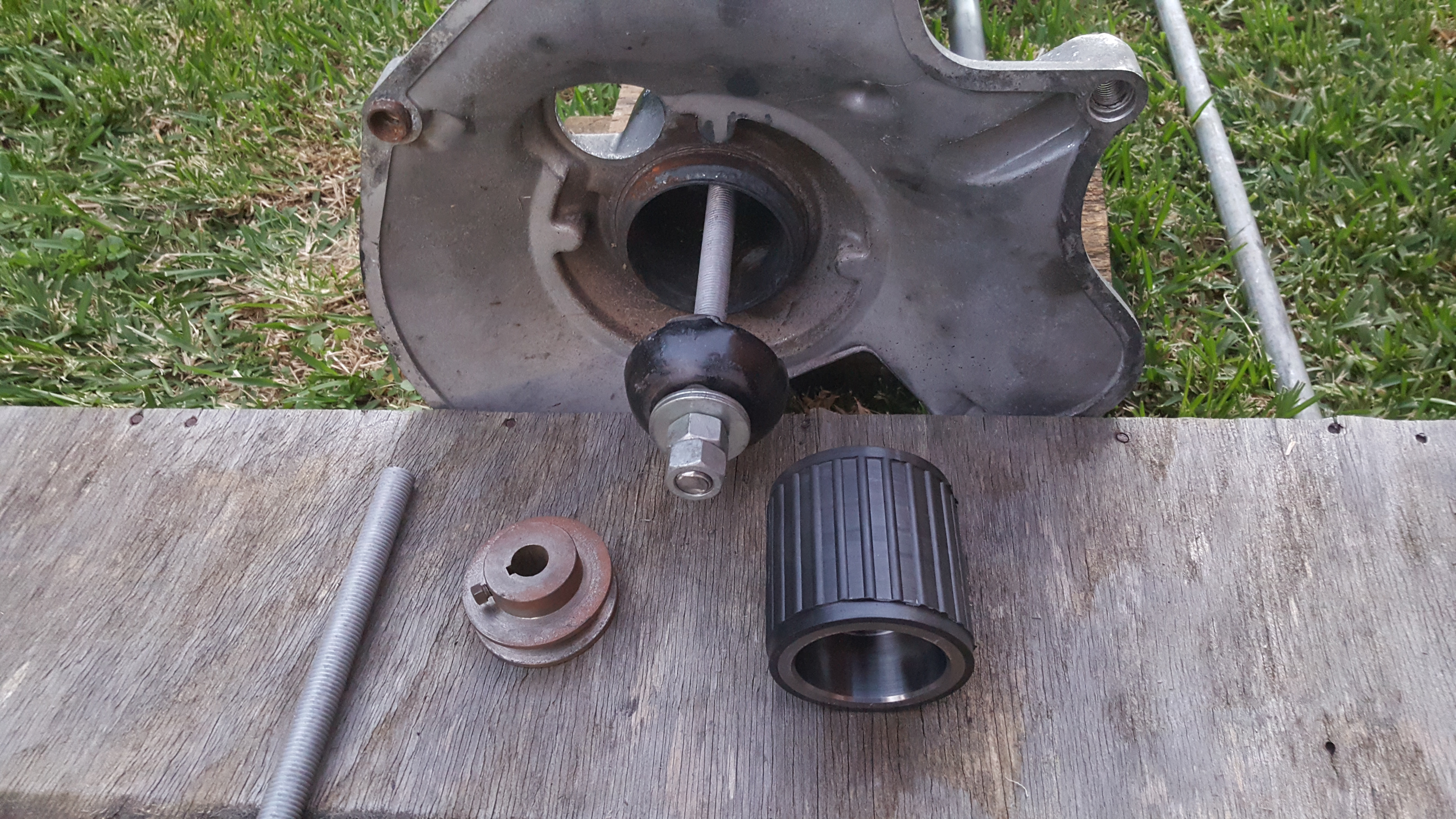
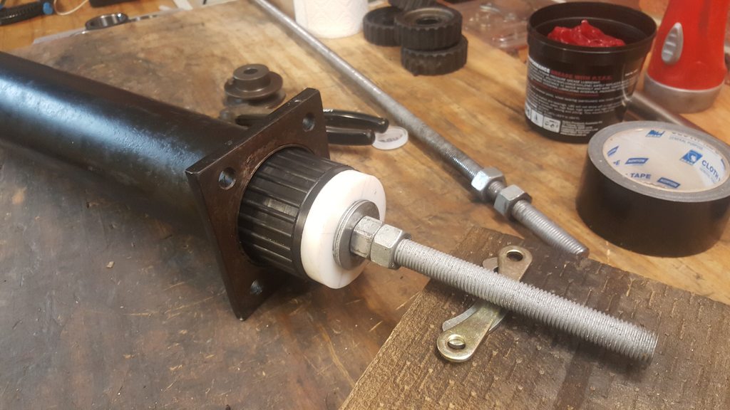
I began the bearing extraction using the threaded rod ‘draw-thru’ method which worked fine to a point. At that point the nut which is pulling the rod through began to deteriorate and damage the threads on the rod I was using galvanised M16 rod and nuts and it may not have been tough enough. At that point I was a bit stuck because I had no way of getting a new threaded rod on the weekend and new M16 nuts so I elected to use a length of pipe to knock the bearings out to the point where they were either side of the shifter screw holes. At that point I applied some WD-40 spray lube through the shifter screw holes and onto the threaded rod , I trimmed the threaded rod down behind the point where the threads were damaged and I completed the last part of the extraction using the threaded rod draw through method with a new nut. The lube seemed to make a difference because the extraction went fine even with the load of 4 bearings. As the bearings reached the end of the TT I placed a couple of wooded blocks between the load plate and the end of the TT so that there was space to accommodate the bearings as they came past the end of the TT. Overall the job was a bit of a pain – mainly because of having to find a new method once the threaded rod threads became damaged. The final draw through was also done manually so that makes it tedious too. It definitely felt like a bit of a victory getting those suckers out. Now I will have to pick up a new length of better quality rod & nuts to draw the new bearings into place.
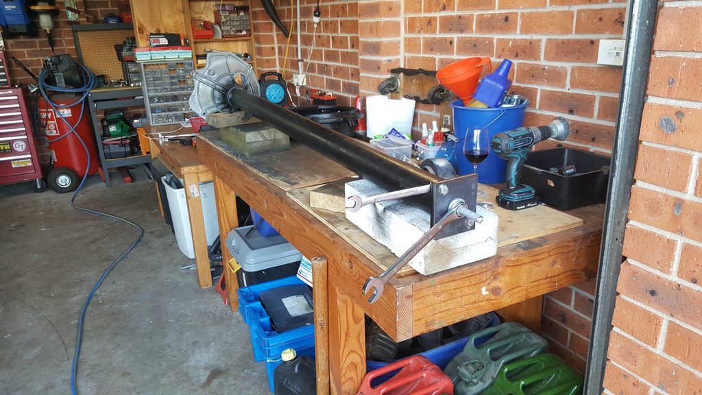
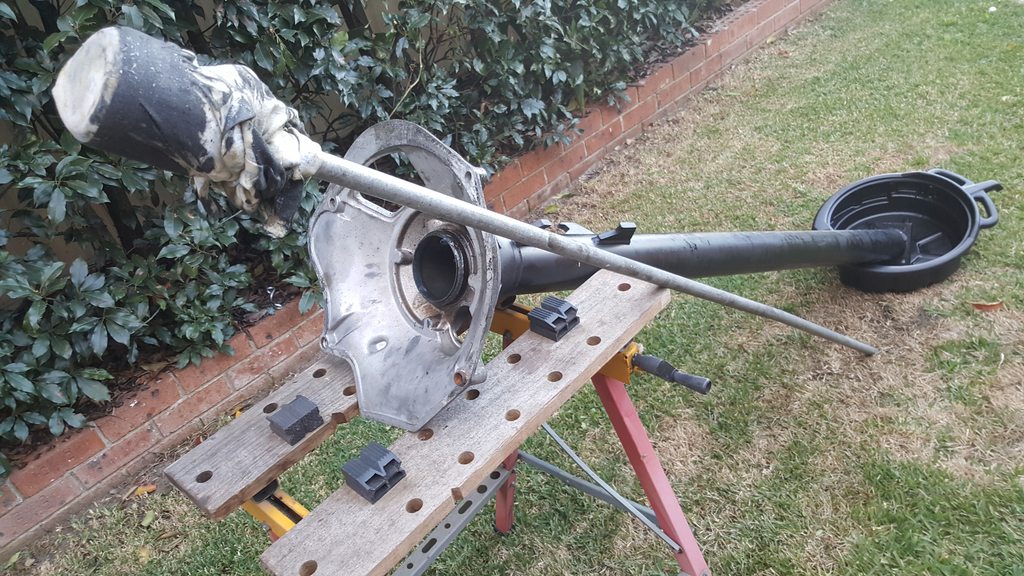
In the pic above, the pipe is sitting on the tail end of the threaded rod and pushing against the 'pull through' which is closely matched to the bearing diameter. This way the pipe I was hammering against was not contacting/damaging the inside of the TT I moved the bearings 2ft or so with this method such that bearings 4/3/2 were on one side of the shifter screw holes and bearing #1 was on the other side of the shifter screw holes.
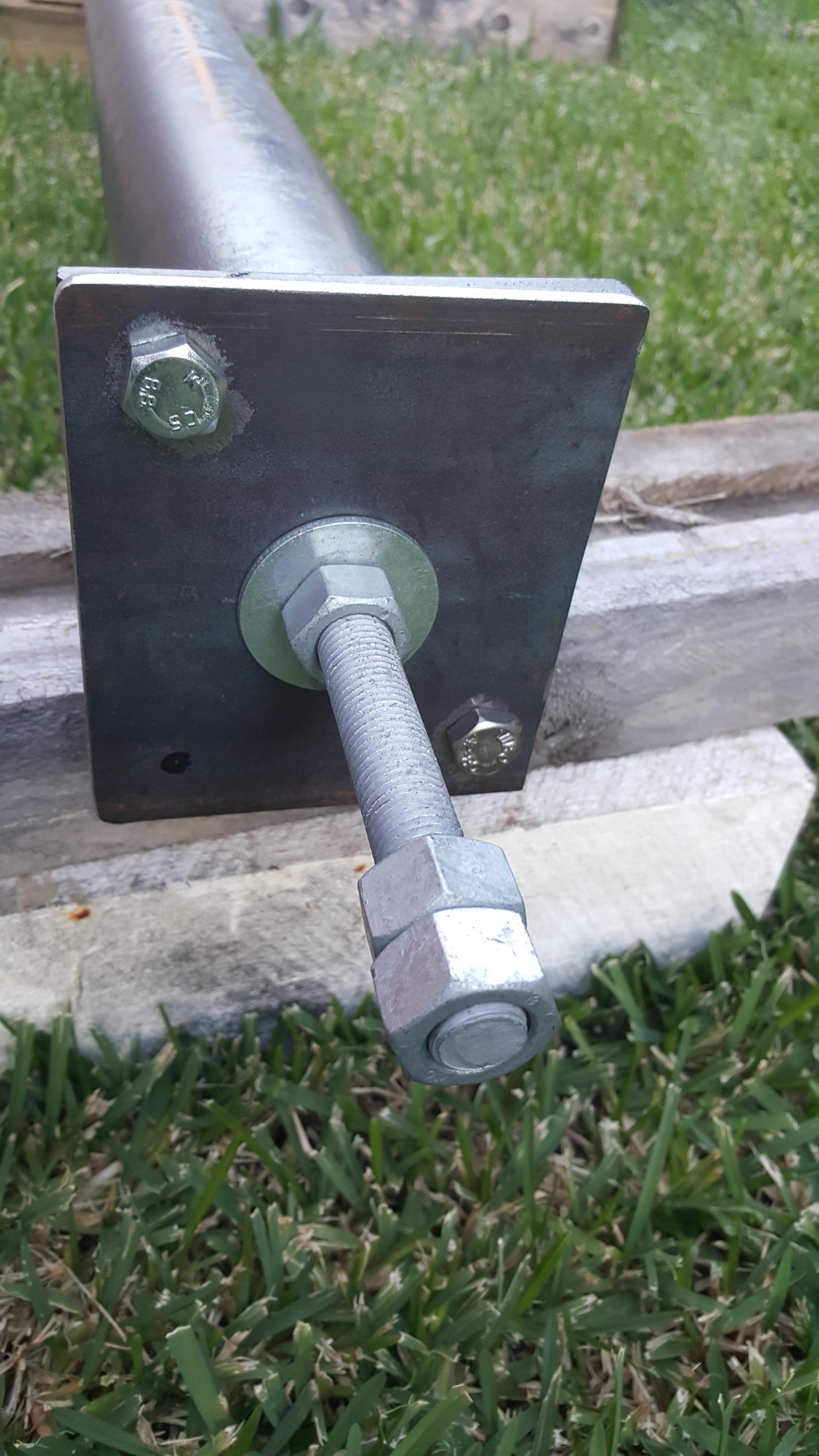
With the threaded rod trimmed down I used this method (above) to draw the bearings the rest of the way out until such time as I needed to put wooden spacers in (below).
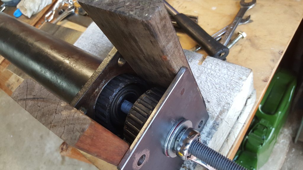
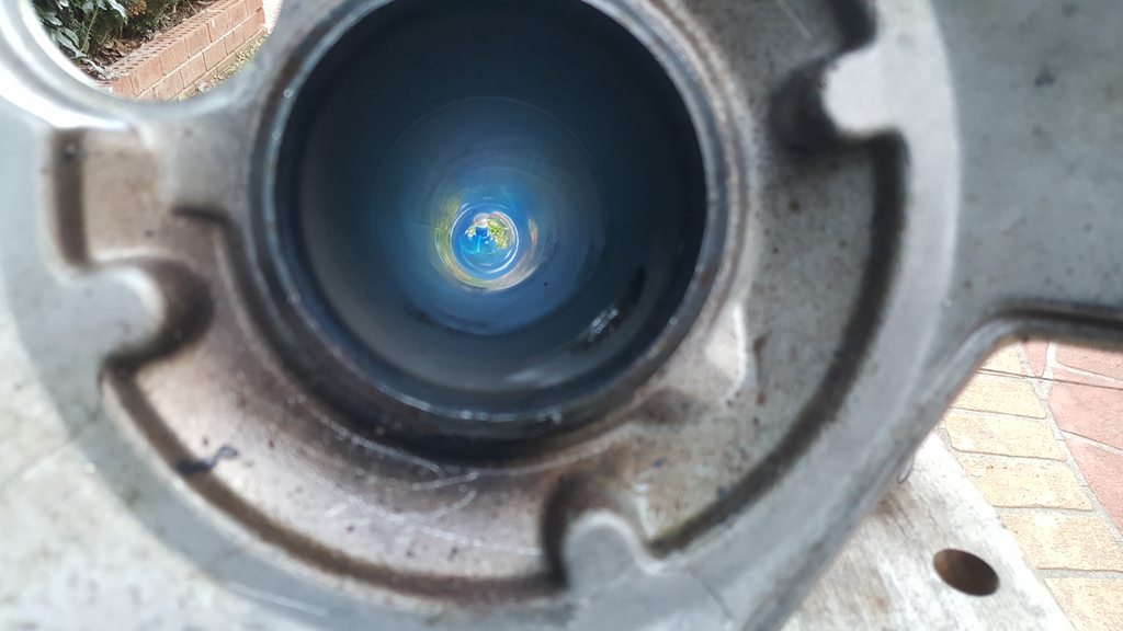
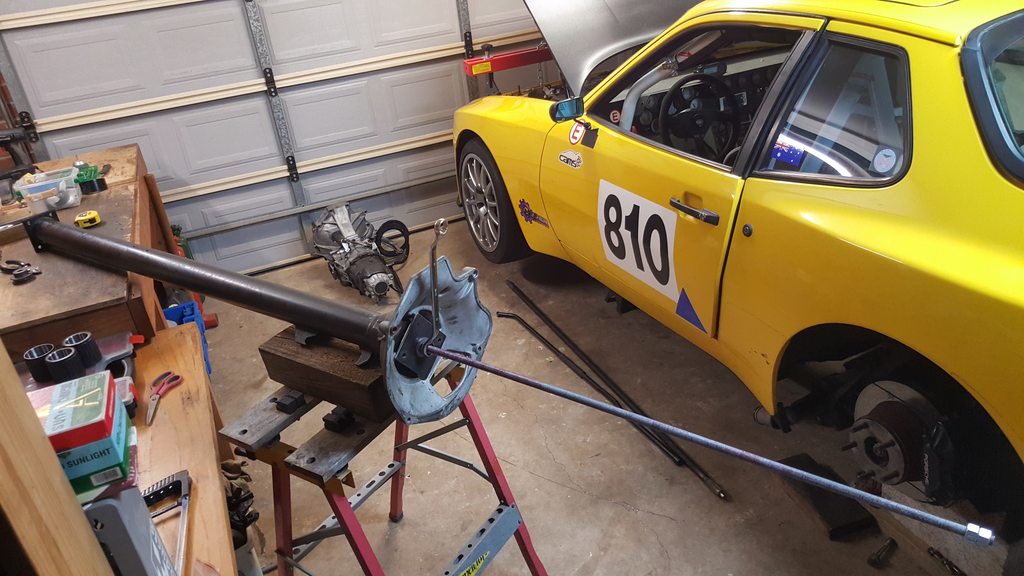
When you get to this stage you'll understand the happy face.
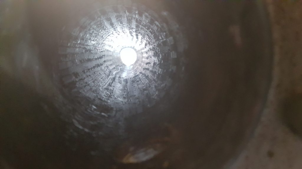
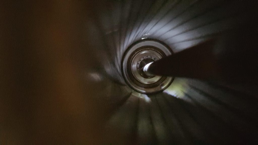
There's definitely noise when each of these bearings is spun. It sounds like there is no lube in there at all
05-29-2017, 12:45 AM
#4
Rennlist Member

Done one myself. Don't think I would do the treaded rod method again. My air gun wouldn't manage the 1/2-13 treaded rod so I ended up cranking it all by hand. It was a very long and tedious process. Maybe a draw bar attached to a come-a-long and draw out the bearings. Should work for install too.
Kudos for tackling such a difficult task.
Kudos for tackling such a difficult task.
05-29-2017, 01:10 AM
#5
Three Wheelin'
Thread Starter
Done one myself. Don't think I would do the treaded rod method again. My air gun wouldn't manage the 1/2-13 treaded rod so I ended up cranking it all by hand. It was a very long and tedious process. Maybe a draw bar attached to a come-a-long and draw out the bearings. Should work for install too.
Kudos for tackling such a difficult task.
Kudos for tackling such a difficult task.
Thanks David, Interesting suggestion re the come-along. Car trailer electric winch might have made short work of things ... possibly lacking finesse for the install depth setting though
 05-29-2017, 03:08 AM
#6
Drifting
Added advice, don't get a stainless steel threaded rod (too pricey anyways) and stainless nuts, I found under a little load when tightening the two stainless metals together they weld themselves. But a plated rod and stainless nut should would work fine. I know many don't know what I'm talking about or have had it happen but it does and when it does it sucks! Like throwing $ away! If the plates nut failed because it's weak then go with a stainless nut on the plates rod and WD40 the rods threads. Good fun, I just had Constentine build mine. Totally worth it to me.
05-29-2017, 04:43 AM
#7
Three Wheelin'
Thread Starter
It seems that I'm only able to get my hands on galv rod at the length I need. It should be ok since I'll only be drawing one bearing at a time and the tube will be clean and lubricated.
Trending Topics
 05-29-2017, 05:51 PM
#9
Sweet write up Kelly Anne, just noticed this thread today!
This is definitely not as easy as others have made it out to be and applaud your finesse in getting to the finish line.
The installation of the Super Bearings should go a bit smoother. Also the depths for each are a bit different from the stock depths.
Hoping to hear of your successful conclusion shortly!
Cheers,
Constantine
05-29-2017, 07:05 PM
#10
Three Wheelin'
Thread Starter
Mark: re the grease, yes definitely!
Constantine: Thanks & agreed it does have its challenges. I'm keen to be on track on 9 Jun so I'll be tackling some of the steps during my free evenings between now and then. As soon as I spun those old bearings I felt this task was validated.
Constantine: Thanks & agreed it does have its challenges. I'm keen to be on track on 9 Jun so I'll be tackling some of the steps during my free evenings between now and then. As soon as I spun those old bearings I felt this task was validated.
05-29-2017, 11:23 PM
#11
Drifting
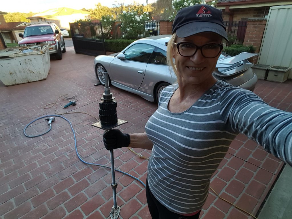
Kelly Anne is that a 2002 911 turbo in that photo behind you? Hahaha and your into your Porsche that deep and dominating the task and confident enough to post it with great detail? I don't know you but I know your awesome!!! That's what's up, You rock!!!
05-30-2017, 12:07 AM
#12
Three Wheelin'
Thread Starter
 05-30-2017, 07:40 AM
#13
Three Wheelin'
Thread Starter
I thought I'd make a start on cleaning the TT and ended up getting as far as setting the first bearing (the one aft of the shift lever). This part all went trouble free. I drew it in by hand rather than power tools because it is evening time. with a thread pitch of about 2mm that made it 340 turns of the wrench but it was all smooth as can be seen from the video clip at the end.
I used kersone to clean the TT, that was easy enough, 3 pull throughs followed by a pull through with wd-40. Lube as supplied by Constantine on the inner rubber splines and lip of the tube as the bearing enters the tube.
Greasing the new galv rod prevented any damage there.
I used kersone to clean the TT, that was easy enough, 3 pull throughs followed by a pull through with wd-40. Lube as supplied by Constantine on the inner rubber splines and lip of the tube as the bearing enters the tube.
Greasing the new galv rod prevented any damage there.
06-04-2017, 06:17 PM
#14
Three Wheelin'
Thread Starter
I finished assembling the torque tube on the weekend. I struggled to press the shaft in by hand so I had to find another way. I ended up using a combination of leverage and I removed the hydraulic ram from my engine hoist to use as a press to complete the job.
The TT re-install has been straight forwards, as was the re-install of the rear suspension assembly. Ran out of time to do put the transaxle back in so that will be tonights job.
A shout-out to Constantine who called from America on Sunday to talk about the problem I had with the drive shaft installation. I can't imagine how his cutsomer service could be any better. Thanks a heap C.
I'll finalise a summary video and post a link when I'm done getting the car back together as I want it on a trailer and track bound Thursday evening.
06-04-2017, 07:45 PM
#15
Hi Kelly Anne,
Thank you for your kind remarks, only wish I could have been there to help!
Looking forward to hear about your driving reports from the track.
Have fun with the reassembly of your 944 racer.
Kind regards,
Constantine
Thank you for your kind remarks, only wish I could have been there to help!
Looking forward to hear about your driving reports from the track.
Have fun with the reassembly of your 944 racer.
Kind regards,
Constantine