When you click on links to various merchants on this site and make a purchase, this can result in this site earning a commission. Affiliate programs and affiliations include, but are not limited to, the eBay Partner Network.
I have a couple old harness I use to harvest color coded wires and to help with diagnostics, etc. I'm planning to make a new fuel injector harness so wanted to see how/where the factory connected wires. Electronically, all 4 injectors run off the same two wires/signal, so in theory you could run two wires only and just t-into them for each injector, but I wanted to see how the factory did it.
For the record, the hot wire starts as a large gauge 12v wire and the factory crimps 4 individual FI wires to it along with a power wire to the KLR and iirc the ISV. The crimp is an insulated copper crimp that's buried deep inside the harness. The switching/ground wires start as 2 wires from the DME (but are connected inside the DME) and each of those two wires end with a similar crimp where two wires branch out of each, so there's one for each injector. If you look at the factory schematic, these copper crimps are actually shown as square boxes with the number 1, 2, and 3 inside. I always wondered what those boxed numbers meant, so now I know...
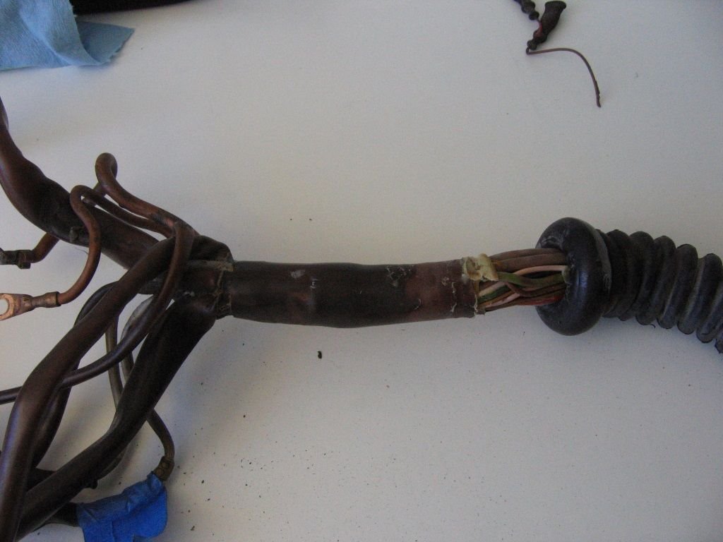
Also, I cut away a bunch of the outer shell to get into the harness and found that the factory actually potted the wires in several places, with several different types of goo, tape, and other filler material. They were glued together mighty tight, which explains why there's simply no way to pull a wire out of the harness. See mess below.
Tom, how are you planning to get your new FI wires through the firewall and down to the DME? I remember reading somewhere else on here that the big firewall boot/snorkel or whatever you call it is also filled with goo/filler material making it impossible to remove and or replace wires that run through it. I'm planning to re-wire the speed and reference sensor wiring and maybe even the fuel injector wires like yourself. I know LR has a tech sheet on poking a new hole in the side of the firewall boot but just wondering if there's another / cleaner way of doing it?
Tom, how are you planning to get your new FI wires through the firewall and down to the DME? I remember reading somewhere else on here that the big firewall boot/snorkel or whatever you call it is also filled with goo/filler material making it impossible to remove and or replace wires that run through it. I'm planning to re-wire the speed and reference sensor wiring and maybe even the fuel injector wires like yourself. I know LR has a tech sheet on poking a new hole in the side of the firewall boot but just wondering if there's another / cleaner way of doing it?
I used the LR speed and ref harness and poked a hole in the big rubber bulkhead grommet, but wish I hadn't. Their injection harness is set up the same. I'm leaning toward cutting the injector harness off where it branches off the main harness under the hood. Then installing a connector right there, so that I can connect one sub-harness for stock injector connectors, or swap it out for different sub harness with EV6/USCAR style connectors. As far as I can tell, there are no failure points between the DME and that point under the hood, so using the original wire should be ok for that portion. But still mulling options...
You can peel / roll back the boot to get access. I just did that with the harness that I rebuilt on my friends car.
I should have done that on my car. I pulled out all of the old unused wires. There is a ton of room in the boot when you do this. I highly recommend doing this. When I get back from holidays I will post some pics of home much extra space there is. I installed all of the LR harnesses in this one. I also discovered a bunch of damaged wires in the boot.....which could be a source for some cars electrical issues. Basically a place for people to consider looking if they can't track down electrical issues.
Originally Posted by markl951
Tom, how are you planning to get your new FI wires through the firewall and down to the DME? I remember reading somewhere else on here that the big firewall boot/snorkel or whatever you call it is also filled with goo/filler material making it impossible to remove and or replace wires that run through it. I'm planning to re-wire the speed and reference sensor wiring and maybe even the fuel injector wires like yourself. I know LR has a tech sheet on poking a new hole in the side of the firewall boot but just wondering if there's another / cleaner way of doing it?
You can peel / roll back the boot to get access. I just did that with the harness that I rebuilt on my friends car.
I should have done that on my car. I pulled out all of the old unused wires. There is a ton of room in the boot when you do this. I highly recommend doing this. When I get back from holidays I will post some pics of home much extra space there is. I installed all of the LR harnesses in this one. I also discovered a bunch of damaged wires in the boot.....which could be a source for some cars electrical issues. Basically a place for people to consider looking if they can't track down electrical issues.
How did you pull the old wire out of the harness? On the harness I just took apart (pictures above) the wires were all seriously cemented in place together under the sheath where it goes through the firewall. Even with the sheathing off it took forever to separate the wires. There's just no way they would have pulled out...
If you grab individual wires you can peel apart kind of like "Jenga" and of course the harness was out of the car. I inquired about getting a whole wack load of different colour wire from a place in Calgary by my work and need to go back and see if they sourced it out for me. I can send you some odd ball colours if they managed to get it in. It was going to be in 1000ft rolls!!! I think that will leave me with enough for a couple of harnesses. Oh and I also pulled pins individually from each terminal location where necessary.
Originally Posted by Tom M'Guinn
How did you pull the old wire out of the harness? On the harness I just took apart (pictures above) the wires were all seriously cemented in place together under the sheath where it goes through the firewall. Even with the sheathing off it took forever to separate the wires. There's just no way they would have pulled out...
If you use a heat gun on low (200F setting) this will soften a lot of the adhesives the factory used to the point of being able to manipulate them. Some of the stuff will be solid at room temp but becomes fairly workable when heated a bit. I can't recall if this worked or not on the snorkel though but I know this worked on the adhesive under the TPS boot.
I took a bunch of pictures of the wire in the snorkel when I disassembled my harness. It's interesting how it all goes together, and the effort they went to to prevent water intrusion.
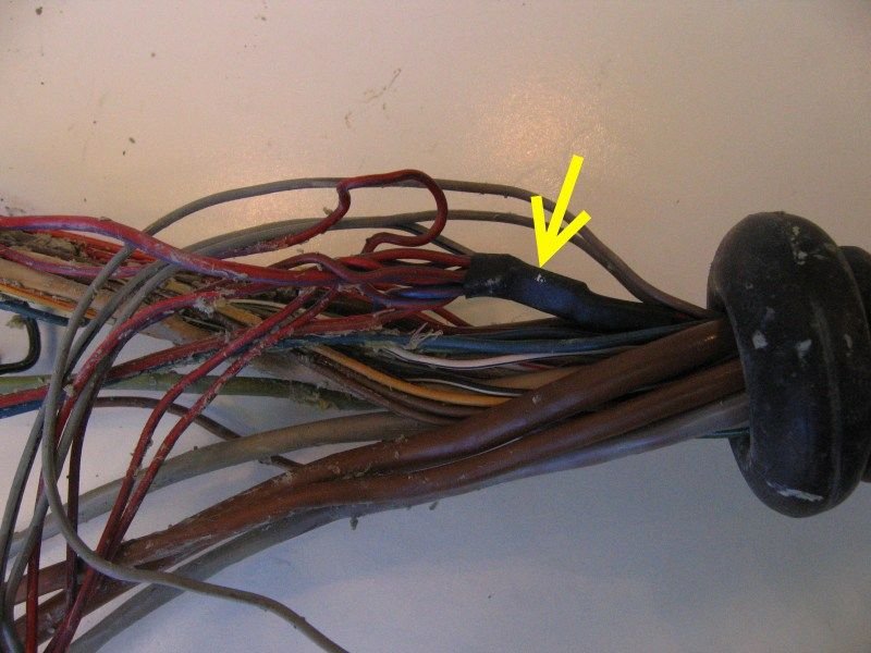
The second to last picture is of one of the welding points for the fuel injector signal wires (WP1/2). The final picture is welding point 3, which supplies power to the injectors (among other things). I thought I had a picture without the heat shrink, but I seem to a have misplaced it. This joint appears to be constructed with compression welding--the wires are just mashed together to form an almost solid block of copper. I haven't been able to find much information on this joining technique or the tools required to do it.
I thought there was a super thin copper foil over those joints, but maybe not. It was so old and dirty under the plastic crimp housing, I may have just been seeing what I expected to see. The hard outer crimp housing is part of the system for sure because once I cut that off I was able to separate the wires relatively easily. They didn't seem fused, just smashed together. Those joints obviously worked for Porsche -- never seen or heard of one of those joints going bad -- but suspect it would be a different story if they weren't buried deep inside the most rigid part of the harness. I'll be using solder and dual-wall adhesive-lined heat shrink instead.
If you use a heat gun on low (200F setting) this will soften a lot of the adhesives the factory used to the point of being able to manipulate them. Some of the stuff will be solid at room temp but becomes fairly workable when heated a bit. I can't recall if this worked or not on the snorkel though but I know this worked on the adhesive under the TPS boot.
That could help. The grey potting material looks like it was supposed to remain soft, but hardened over the years. So heat might help there. I could see some of the bigger sheathed wires pulling out under just the right circumstances, but a lot of them are just trapped and would never pull out, with or without the potting material. The fuel injection wires, for example, have those big crimp joints that act like grappling hooks, and some of the wires get interlaced/tangled with unrelated wires, meaning something would have to snap before they came out...
I have a J-standard soldering book on my desk at work. I have no idea if it would have any info relative to that type of wiring but when I get back from holidays I will have a look. I'm curious now What a rats nest of wiring though on both harnesses I worked on.
Originally Posted by Tom M'Guinn
I thought there was a super thin copper foil over those joints, but maybe not. It was so old and dirty under the plastic crimp housing, I may have just been seeing what I expected to see. The hard outer crimp housing is part of the system for sure because once I cut that off I was able to separate the wires relatively easily. They didn't seem fused, just smashed together. Those joints obviously worked for Porsche -- never seen or heard of one of those joints going bad -- but suspect it would be a different story if they weren't buried deep inside the most rigid part of the harness. I'll be using solder and dual-wall adhesive-lined heat shrink instead.
Reference book for wire harnesses on my desk at work
Just as an FYI the grey goop in the harness is a fire retardant. Car catches fire and that stuff expands at a rapid rate with heat to block off the pass through the fire wall.


 07-23-2016, 10:21 PM


 What a rats nest of wiring though on both harnesses I worked on.