
Grinding a slightly offcenter reluctor wheel? Megasquirt losing teeth count
 12-20-2013, 03:02 PM
#1
Race Car
Thread Starter
Join Date: Mar 2012
Location: Austin TX, drinking beer in the garage
Posts: 3,602
Likes: 0
Received 7 Likes
on
7 Posts
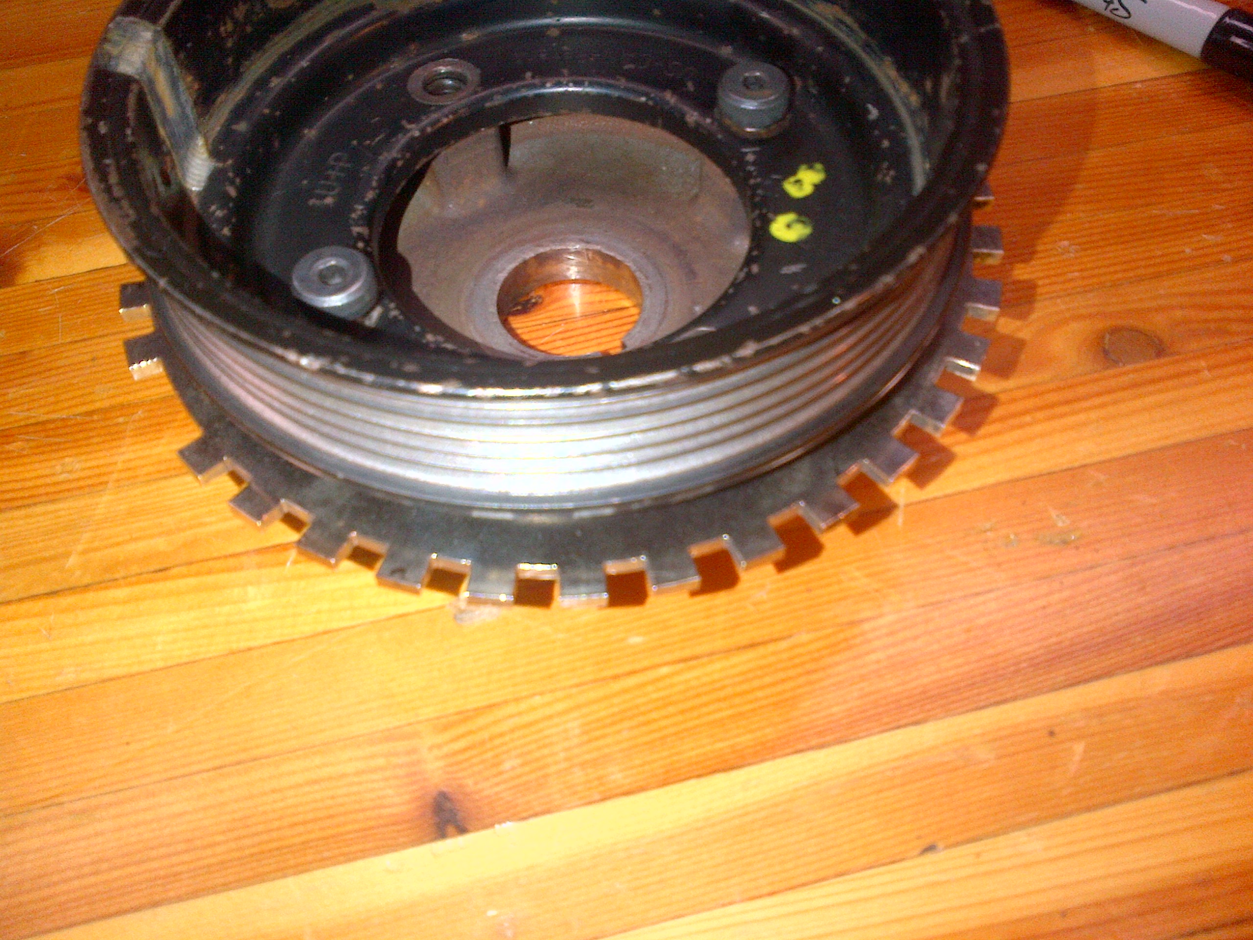
I've got a question, or more of a "what would you do" question. I'm finished installing megasquirt in my car, but it won't run correctly because it keeps losing tooth count. I have a 36-1 wheel welded to my crank pulley, but it was welded slightly off center so the difference in height between the tallest and shortest teeth is ~1.5mm. The wheel is off to one side, so 18 continuous teeth have been marked and I was wondering, do you guys think I can just take a grind wheel to those teeth and take a mm or so off, or will I ruin the teeth? The specified air gap for the sensor is 1mm. I'm so close...getting the triggering figured out is the last step.
 12-21-2013, 12:47 PM
#2
Race Car
Thread Starter
Join Date: Mar 2012
Location: Austin TX, drinking beer in the garage
Posts: 3,602
Likes: 0
Received 7 Likes
on
7 Posts
I never thought about the taper... that will definitely increase the size of the teeth if I grind it. Damnit...I don't know anyone with a lathe.
12-21-2013, 02:29 PM
#3
Three Wheelin'
You Definitely need a lathe. They're fairly common, look for a machine or fabrication shop. I have a lathe built by Atlas in the 50's in my shop, it's wonderful for jobs like yours.
12-28-2013, 01:30 PM
#4
Race Car
Thread Starter
Join Date: Mar 2012
Location: Austin TX, drinking beer in the garage
Posts: 3,602
Likes: 0
Received 7 Likes
on
7 Posts
Well folks, it is running! I decided to do a little experiment, I figured I had nothing to loose by grinding the wheel down so that is what I did. I was surprised when it started, and even more surprised when it idled better than factory. I didnt expect it to rev well, but it does. It even drives, though it wont rev past 3500 rpm. It feels like it hits a hard cut, and megasquirt registers a loss of synch. It doesnt stall though, it just feels like its hitting a rev limiter. From my research I think it is because I have not set the trigger angle yet with a timing light, so I'm sure it is off a bit and as rpm rises, the error becomes larger and larger until combustion is not possible. I will try setting up the trigger angle today, but while its running and revving between idle and 3500 rpm, ignition timing is really stable and predicable so no ill effects from grinding the wheel. Truthfully, the taper on the teeth is very slight and the error was not very large, so the difference in width between ground and unground teeth is inconsequential. I'm having an issue with my intake temp sensor also, both sensors I have ( an open element and a closed element) are not reading and I doubt they are both no good, I'm going to get a battery today so I can check them with my multimeter but i'm pretty sure its a wiring issue. I believe the car will be driving by weeks end.
Update: Both intake temp sensors are good and show the exact same resistance at various temperatures. I tested the wiring to the megasquirt and it seems ok also, the two IAT wires measure ~2k when I put a meter across them. I dont know if this is normal. I checked the wiring again visually and it seems fine, tomorrow I'm going to wire a spare, known working IAT sensor directly into the megasquirt in cabin to eliminate wiring as a variable and see if I can't get it to register. I'm also having issues with my MAP sensor, which is partly because I'm not certain which sensor I was sent. It is supposed to be a 3 bar, but its not a GM factory sensor so I'm having a hard time finding info on it. It reads high, 50-55 kpa at idle, which does not correlate to the 20" HG my boost/vac gauge shows. With the car off and key on its showing ~150 kpa which is obviously wrong since ambient pressure at my altitude is 99 kpa. It also reads incorrectly when I rev it, but it idles well. This is when I am using the GM 3 bar presets in megasquirt. If I change the presets to a GM 2 bar, it reads correctly with the car off and key on, right around 104 kpa but the car doesnt run! it stalls as soon as I try to start it and I dont know why...This is driving me crazy.
Update: Both intake temp sensors are good and show the exact same resistance at various temperatures. I tested the wiring to the megasquirt and it seems ok also, the two IAT wires measure ~2k when I put a meter across them. I dont know if this is normal. I checked the wiring again visually and it seems fine, tomorrow I'm going to wire a spare, known working IAT sensor directly into the megasquirt in cabin to eliminate wiring as a variable and see if I can't get it to register. I'm also having issues with my MAP sensor, which is partly because I'm not certain which sensor I was sent. It is supposed to be a 3 bar, but its not a GM factory sensor so I'm having a hard time finding info on it. It reads high, 50-55 kpa at idle, which does not correlate to the 20" HG my boost/vac gauge shows. With the car off and key on its showing ~150 kpa which is obviously wrong since ambient pressure at my altitude is 99 kpa. It also reads incorrectly when I rev it, but it idles well. This is when I am using the GM 3 bar presets in megasquirt. If I change the presets to a GM 2 bar, it reads correctly with the car off and key on, right around 104 kpa but the car doesnt run! it stalls as soon as I try to start it and I dont know why...This is driving me crazy.
Last edited by Dougs951S; 12-29-2013 at 03:49 AM.
12-29-2013, 05:21 PM
#5
Addict
Rennlist Member
Rennlist Member
If you need to redo it, here is what I did with my MegaSquirt setup for triggering.
I used the 6 inch 36-1 wheel from this guy
http://goingsuperfast.com/Trigger-wheels.html
And some shoulder bolts from McMaster, part number 92981A198
It then assembles very nicely into this. The alt pulley had to be drilled slightly for the shoulder bolts, which keep everything tight and centered. The trigger wheel is designed to fit over the pulley already so it is very self centering and doesnt need to be welded.
More pictures are in
http://thedge.info/rennlist/cranktrigger/
12-30-2013, 04:56 AM
#6
Race Car
Thread Starter
Join Date: Mar 2012
Location: Austin TX, drinking beer in the garage
Posts: 3,602
Likes: 0
Received 7 Likes
on
7 Posts
THANK YOU and please, post pictures of the sensor bracket! I want to see how its done with the wheel bolted to the rear of the pulley.
12-31-2013, 09:33 PM
#7
Race Car
Thread Starter
Join Date: Mar 2012
Location: Austin TX, drinking beer in the garage
Posts: 3,602
Likes: 0
Received 7 Likes
on
7 Posts
I went ahead and ordered the 6 inch bolt on trigger wheel. Wanted to ask you too, does one HAVE to use those shoulder bolts for any particular reason or can I just use slightly longer M6 hex bolts? They should do just as good a job I think of keeping everything tight and centered, unless I'm missing something.
Rob, You are not going to be able to get the stock triggers to work in microsquirt unless you go through the trouble of removing a tooth from the flywheel ring gear. Even then, that is only part of the issue in that MS has a hard time dealing with a trigger wheel that has that many teeth. I tried very hard to get the stock sensors working and decided it was voodoo to get it right. I was at least smart enough to leave the factory harness intact so my car runs on the DME by swapping the speed sensor from the trigger wheel input back to the stock sensor and then swapping the microsquirt for the DME back into the 35 pin connector. Sort of a "dual boot" setup, though it runs pretty poorly on the DME since by now the car has been setup to vent to atmosphere and therefore it really needs to be running speed density for it to not run pig rich and try to stall when you let off the throttle in boost.
Rob, You are not going to be able to get the stock triggers to work in microsquirt unless you go through the trouble of removing a tooth from the flywheel ring gear. Even then, that is only part of the issue in that MS has a hard time dealing with a trigger wheel that has that many teeth. I tried very hard to get the stock sensors working and decided it was voodoo to get it right. I was at least smart enough to leave the factory harness intact so my car runs on the DME by swapping the speed sensor from the trigger wheel input back to the stock sensor and then swapping the microsquirt for the DME back into the 35 pin connector. Sort of a "dual boot" setup, though it runs pretty poorly on the DME since by now the car has been setup to vent to atmosphere and therefore it really needs to be running speed density for it to not run pig rich and try to stall when you let off the throttle in boost.
Trending Topics
12-31-2013, 09:47 PM
#8
Addict
Rennlist Member
Rennlist Member
I went ahead and ordered the 6 inch bolt on trigger wheel. Wanted to ask you too, does one HAVE to use those shoulder bolts for any particular reason or can I just use slightly longer M6 hex bolts? They should do just as good a job I think of keeping everything tight and centered, unless I'm missing something.
12-31-2013, 09:50 PM
#9
Race Car
Thread Starter
Join Date: Mar 2012
Location: Austin TX, drinking beer in the garage
Posts: 3,602
Likes: 0
Received 7 Likes
on
7 Posts
Did you order a sensor bracket from the same company, or did you fab it? I've got a really good bracket I fabbed up for my first trigger wheel attempt and I know it works well, but my first trigger wheel is mounted to the front of the pulley instead of the back. I havnt looked yet to see if I can modify it or flip it around to use it with a trigger wheel mounted to the rear of the pulley. That'd sure save me some hassle.
12-31-2013, 10:02 PM
#10
Addict
Rennlist Member
Rennlist Member
Thanks for posting this. 40 dollars and a mcmaster order is much cheaper than the close to 100 dollar pulley that has been posted on here before. I may end up trying this on the 924S after giving the stock trigger setup a chance for future plug and play possibilities.
By any chance, do you have pictures of the sensor bracket as well? That would be greatly appreciated.
By any chance, do you have pictures of the sensor bracket as well? That would be greatly appreciated.
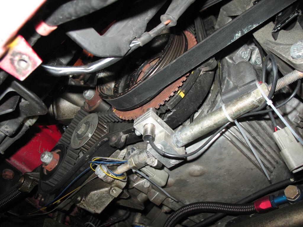
Basically it just mounts to the alternator adjuster.
Messy shot from driving in snow and trying a different sensor hence wire strung all over.
 12-31-2013, 10:06 PM
#11
Race Car
Thread Starter
Join Date: Mar 2012
Location: Austin TX, drinking beer in the garage
Posts: 3,602
Likes: 0
Received 7 Likes
on
7 Posts
That bracket will not work if I am not running A/C but still have the alternator in stock location, right? Didn't realize Chris' bracket was designed to be used with that particular trigger wheel. i'll have to take a look at the geometry dictated by my alternator location and fab something up. Any chance you'd mind sharing your .msq so I could see if some setting I'm using is causing me to not get a reading on my MAT and wideband o2?
Last edited by Dougs951S; 01-01-2014 at 03:30 AM.
01-02-2014, 04:57 AM
#12
Three Wheelin'
That bracket is mounted very wrong. It should be on engine block not on ancillery mounting rod as with revs it will vibrate and not together with crank pulley. No matter how strong it feels by hand, it will cause problems and half of your current issue is related to the sensor mounting location.
Regarding off-center trigger wheel, after mounting it onto the pulley, there is almost always a need to machine a bit it on the lathe. This is how it is done properly as it is nearly impossible to get centered perfectly otherwise. usually we do it so that we machine a ridge onto the pulley if possible and make trigger wheel on the CNC waterjet that corresponds to the ridge diameter so it is well centered but even then we put it onto the lathe to make sure it is absolutely perfect.
Regarding off-center trigger wheel, after mounting it onto the pulley, there is almost always a need to machine a bit it on the lathe. This is how it is done properly as it is nearly impossible to get centered perfectly otherwise. usually we do it so that we machine a ridge onto the pulley if possible and make trigger wheel on the CNC waterjet that corresponds to the ridge diameter so it is well centered but even then we put it onto the lathe to make sure it is absolutely perfect.
01-02-2014, 11:45 AM
#13
Addict
Rennlist Member
Rennlist Member
That bracket is mounted very wrong. It should be on engine block not on ancillery mounting rod as with revs it will vibrate and not together with crank pulley. No matter how strong it feels by hand, it will cause problems and half of your current issue is related to the sensor mounting location.
Regarding off-center trigger wheel, after mounting it onto the pulley, there is almost always a need to machine a bit it on the lathe. This is how it is done properly as it is nearly impossible to get centered perfectly otherwise. usually we do it so that we machine a ridge onto the pulley if possible and make trigger wheel on the CNC waterjet that corresponds to the ridge diameter so it is well centered but even then we put it onto the lathe to make sure it is absolutely perfect.
Regarding off-center trigger wheel, after mounting it onto the pulley, there is almost always a need to machine a bit it on the lathe. This is how it is done properly as it is nearly impossible to get centered perfectly otherwise. usually we do it so that we machine a ridge onto the pulley if possible and make trigger wheel on the CNC waterjet that corresponds to the ridge diameter so it is well centered but even then we put it onto the lathe to make sure it is absolutely perfect.
Next setup will be different, 60-2 machined flywheel. But that one worked well enough.
01-02-2014, 02:14 PM
#15
Instructor

Join Date: Feb 2010
Posts: 100
Likes: 0
Received 0 Likes
on
0 Posts