
Fix Odometer and LED light upgrade
 01-11-2013, 10:17 AM
#31
I might be the only person who is willing to do this mod but I may as well share it with anybody else that is crazy enough. I spent over 200$ in test components but I'm not counting since the same parts can be used in my other planned projects.
I'm looking into adding daytime running lights and also mod the tail lights and turn signals. I love the design possibilities and the performance of LED lights. I'm also afraid that the standard light bulbs will end up damaging the gauge cluster and be a very expensive repair in the near future.
I'm looking into adding daytime running lights and also mod the tail lights and turn signals. I love the design possibilities and the performance of LED lights. I'm also afraid that the standard light bulbs will end up damaging the gauge cluster and be a very expensive repair in the near future.
 01-11-2013, 05:03 PM
#32
Instructor
Thread Starter

Join Date: Apr 2011
Posts: 121
Likes: 0
Received 0 Likes
on
0 Posts
I was thinking of using something l ike this
05-31-2013, 03:06 PM
#33
Instructor
Thread Starter
Join Date: Apr 2011
Posts: 121
Likes: 0
Received 0 Likes
on
0 Posts
I went ahead and purchased this. It will let me do PWM LED dimming. It's supposed to handle up to 8 amps, and I'll be running a lot less than that, so I should be able to run all the dash lights from this. I may put adjustable series resistors in for different groups of LEDs to adjust the relative brightness and use the PWM to provide master control of all. With luck, I'll be able to use the factory resistor in the dash to control the PWM chip so everything will be hidden.
The factory dash potentiometer was about 3 ohms in series with the dash lights. Rotating the dimmer on the dash varies the resistance from zero ohms to 3 ohms. Only 2 leads on that potentiometer were used. The LED dimmer I bought used a 1K ohm potentiometer and all 3 leads were used. It would have been easy to remotely mount the pot on that dimmer (it came with a remote cable and a black **** mounted on the front of the box, with the circuit at the back of the box). The LED dimmer pot would easily mount in the empty slot on the dash to the left of and adjacent to the factory dimmer ****, but I wanted to see how the lights appeared after just upgrading wattage and fixing the reflector parts.
The factory dash lights were all 2 watt bulbs, and I upgraded to Sylvania 3.4 watts per the bulb list in the Clark's Garage notes on this repair. The silver on the transparent plastic that funnels the light into the gauges was in bad shape as is typical for a car of this vintage, so I used a tiny amount of lacquer thinner to remove it and covered it over with aluminum foil - shiny side towards the plastic. I covered over the aluminum foil with more tape (some aluminum tape I had) to protect it. The result of these two fixes (more light and and repairing the silver reflector) was more than satisfactory, so I decided not to install the LEDs and LED dimmer.
BTW, there is a large resistor on the back of the panel. Mine had a broken lead. That resistor just plugs into two connectors and I was able to just bend the broken lead and plug it back in.
I checked all the bulbs on my'86 944T. They were all original. There were 3 larger lighting bulbs and 9 or so small indicator bulbs. Not a single one was burned out after 27 years! I figured the LED lifetime issue wasn't really important - I'd rather keep it original. If I need more light, I can go with the 3.8 bulbs and line the bulb surround with aluminum to minimize the chance of heat damage. I just cleaned all the contacts and the bulbs - some had dust on them that darkened them a bit. The result looked great.
I may eventually use the LED strips for under dash lighting, as it is nice to be able to see the floor at night, if I drop something, but the instrument lighting seems fine.
06-03-2013, 02:10 PM
#35
Burning Brakes
Join Date: Mar 2006
Location: Orlando,FL (formerly UK)
Posts: 1,215
Likes: 0
Received 0 Likes
on
0 Posts
To be technically accurate, LEDs do NOT require a constant current.
They do inded have a maximum current and a largely fixed forward drop voltage (which varies with several factors including color).
They can be perfectly well dimmed with a variable voltage so long as they have a fixed resistance in series... constant current sources simply make them constantly bright with varying sully voltage.
The problem with constant voltage and resistive dimming is that LEDs consume FAR less current than their incandescent equivalents, so the resistance change is negligible.
I've done it before, and have to pull my instruments again to fix a non-working odometer, so will try to take photos.
Keith
06-07-2013, 04:09 PM
#36
Instructor
Thread Starter
Join Date: Apr 2011
Posts: 121
Likes: 0
Received 0 Likes
on
0 Posts
This is true, but perhaps misleading. LED brightness control is achieved by pulse modulation, not just constant current.
I agree with this, althiough the max current is rated two ways - max continuous current and max pulse current.
It's very hard to get them to operate with the full range of brightness they can produce with just variable voltage/resistive control. There are two problems.
At the low end - The LED won't even turn on until sufficient voltage is applied. A good LED dimming circuit will apply sufficient voltage to turn on the LED, but will then turn it off for 10X the length of time it was on. By doing this repeatedly - off for longer than on, and by varying the duty cycle, the LED can be made dimmer than it will appear with the LED at its minimum turn on voltage.
At the bright end - You can get more apparent brightness by overdriving the LED (brighter and more current than it can continuously sustain), then turning it off long enough for the LED to cool. The apparent brightness is greater this way. Of course, this isn't something we need for the instrument lighting of a 951
I've been driving my "repaired" design with clean higher wattage incandescents for a while now, and I'm very happy. It's much brighter than before - too bright for normal night driving - so I have to turn down the brightness, where before I had it maxed out. I didn't even put in the 3.9 watts I could have used, just 3.4 watts, up from the 2 watt dirty bulbs with bad silver reflector paint that was there before.
They do inded have a maximum current and a largely fixed forward drop voltage (which varies with several factors including color).
They can be perfectly well dimmed with a variable voltage so long as they have a fixed resistance in series... constant current sources simply make them constantly bright with varying sully voltage.
At the low end - The LED won't even turn on until sufficient voltage is applied. A good LED dimming circuit will apply sufficient voltage to turn on the LED, but will then turn it off for 10X the length of time it was on. By doing this repeatedly - off for longer than on, and by varying the duty cycle, the LED can be made dimmer than it will appear with the LED at its minimum turn on voltage.
At the bright end - You can get more apparent brightness by overdriving the LED (brighter and more current than it can continuously sustain), then turning it off long enough for the LED to cool. The apparent brightness is greater this way. Of course, this isn't something we need for the instrument lighting of a 951
I've been driving my "repaired" design with clean higher wattage incandescents for a while now, and I'm very happy. It's much brighter than before - too bright for normal night driving - so I have to turn down the brightness, where before I had it maxed out. I didn't even put in the 3.9 watts I could have used, just 3.4 watts, up from the 2 watt dirty bulbs with bad silver reflector paint that was there before.
07-31-2013, 04:27 PM
#37
Addict
Rennlist Member
Rennlist Member
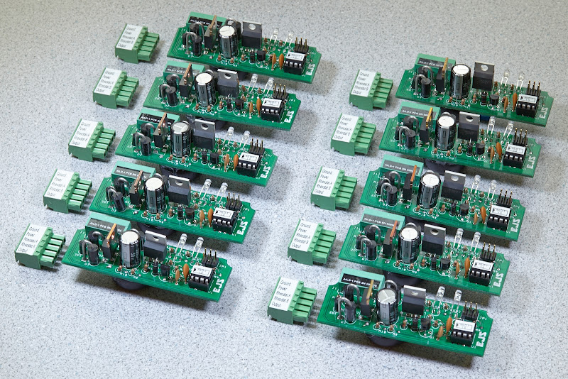
I just noticed this thread and thought I'd offer some information on the "PWM dimming of instrumentation LEDs" topic. Based on what I read earlier in this thread, I can see that at least a couple of you understand the issues and probably experienced the same frustrations as I did in seeking (and never finding) commercial LED dimmer products that satisfy the requirements. The two requirements typically not met by readily-available PWM-based dimmers are: (1) high-side driving (i.e., suitable for use with common-ground-wired lighting), and (2) controlled via the car's existing low-resistance rheostat/potentiometer.
"Some guy" got this done a few months ago and sold out the first batch of ten units within a few days (another batch is almost complete). I've been trying to satisfy the demand from the Rennlist 928 community first, but will probably be ready to expand distribution fairly soon.
An early prototype did use an Arduino Pro Mini along with additional interface circuitry, but the final unit uses an AVR ATtiny85 microcontroller along with additional circuitry (for power conditioning, output driving, current limiting, etc.) on a custom PCB.
See AILD-1 Automotive Instrumentation Lighting Dimmer: A Solution to Dimming After Upgrading Instrumentation Lighting to LEDs for more information on the final unit. The thread PWM dimmer for instrument backlighting after upgrading to LEDs might be interesting if you want some insight into the development of this unit.
It turned out to be way more work than I was expecting. Getting a prototype "working" was fairly easy. Addressing all the subtle issues (e.g., making sure it's not spewing out all sorts of weak radio station killing RFI like so many PWM drivers do), PCB design, enclosure design and production, etc., took considerably more time.


got this done a few months ago and sold out the first batch of ten units within a few days (another batch is almost complete). I've been trying to satisfy the demand from the Rennlist 928 community first, but will probably be ready to expand distribution fairly soon.An early prototype did use an Arduino Pro Mini along with additional interface circuitry, but the final unit uses an AVR ATtiny85 microcontroller along with additional circuitry (for power conditioning, output driving, current limiting, etc.) on a custom PCB.
See AILD-1 Automotive Instrumentation Lighting Dimmer: A Solution to Dimming After Upgrading Instrumentation Lighting to LEDs for more information on the final unit. The thread PWM dimmer for instrument backlighting after upgrading to LEDs might be interesting if you want some insight into the development of this unit.
It turned out to be way more work than I was expecting. Getting a prototype "working" was fairly easy. Addressing all the subtle issues (e.g., making sure it's not spewing out all sorts of weak radio station killing RFI like so many PWM drivers do), PCB design, enclosure design and production, etc., took considerably more time.
Last edited by Ed Scherer; 08-01-2013 at 01:22 PM.