When you click on links to various merchants on this site and make a purchase, this can result in this site earning a commission. Affiliate programs and affiliations include, but are not limited to, the eBay Partner Network.
One thing I noticed is that the condition of the copper strands can be pretty bad even though the insulation looks good. On a well-sealed wire, the copper will still be copper-looking and shiny under the insulation, whereas on some (many) wires the copper turns a very dark crust brown/black. It usually starts at an exposed end, but over the years that corrosion just travels the entire length of the wire. They still work, and in most circuits probably wouldn't do much harm, but extra resistance can cause headaches in come circuits. Just something to keep in mind...
One thing I noticed is that the condition of the copper strands can be pretty bad even though the insulation looks good. On a well-sealed wire, the copper will still be copper-looking and shiny under the insulation, whereas on some (many) wires the copper turns a very dark crust brown/black. It usually starts at an exposed end, but over the years that corrosion just travels the entire length of the wire. They still work, and in most circuits probably wouldn't do much harm, but extra resistance can cause headaches in come circuits. Just something to keep in mind...
Yes for the effort it takes to clean it, swap connectors, etc. I'd replace ALL the wire, not just the ends. By now the corrosion has likely climbed it's way under most of the insulation.
A good little tip, if it hasn't been mentioned in here already, is to use a quick unpick to quickly strip the old covering off the harness.
I used techflex braid to rewrap mine.
I had to look up unpick...should have just asked the wife and I wish I would have waited for your reply...I went razor blade and patience. Quite a process just to get it stripped.
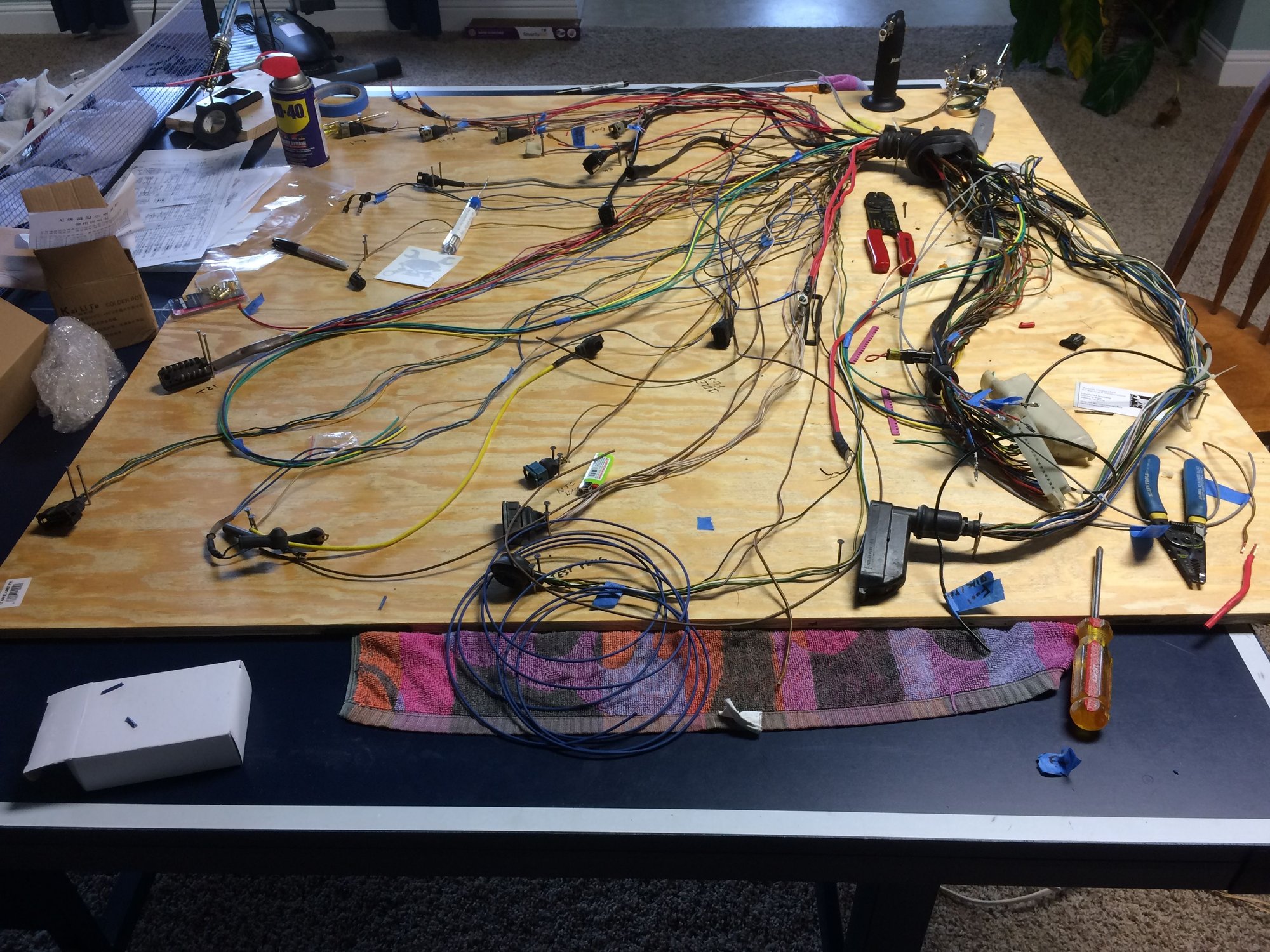
Progress is slow but moving. This is not a project to rush IMO. finally decided to get a 4x4 sheet of plywood like Shawn....this made things much easier to keep organized. Not all wires run through the fire wall, Some are routed back to other connectors in the engine bay like the T21 plug so the plywood help keep things straight.
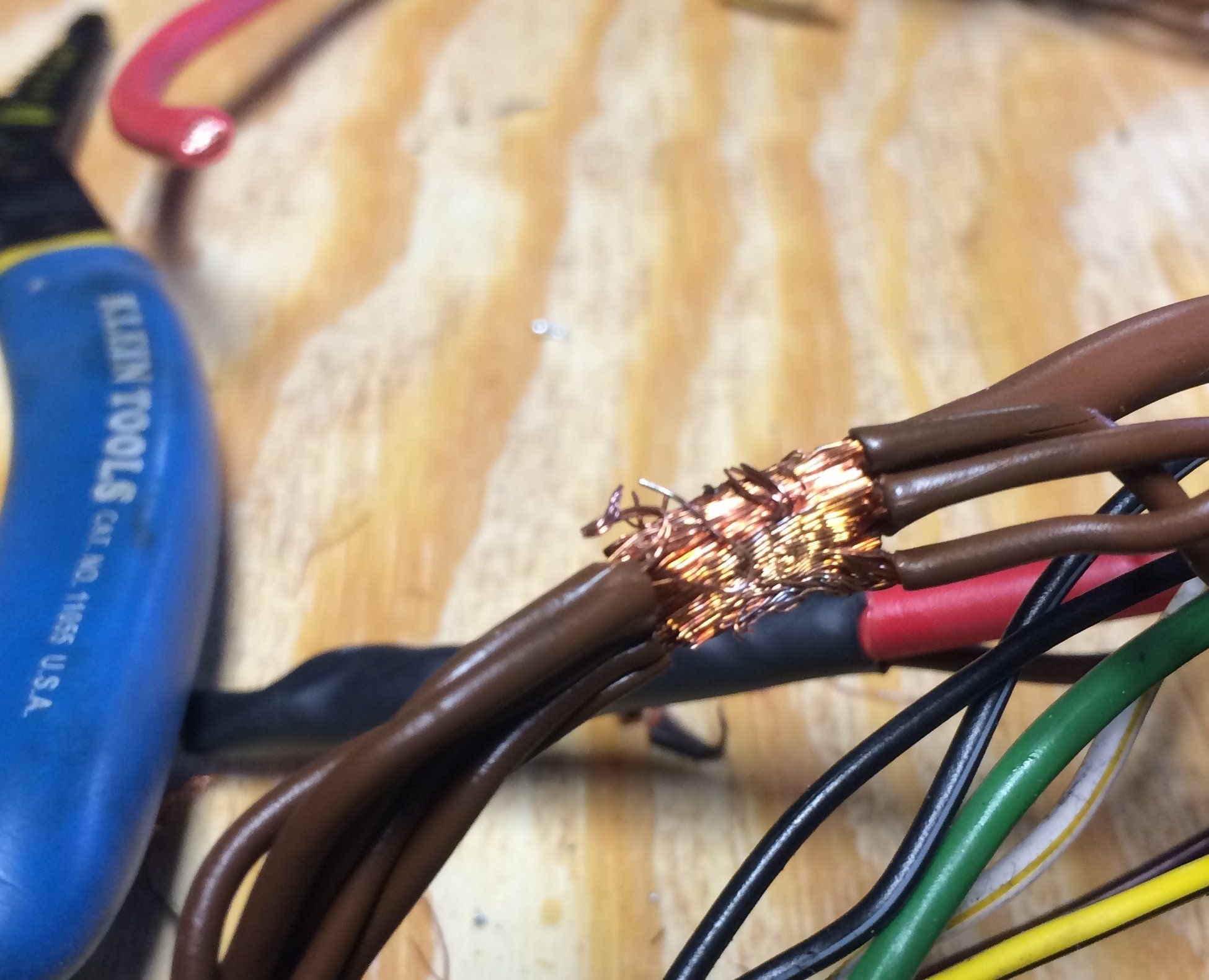
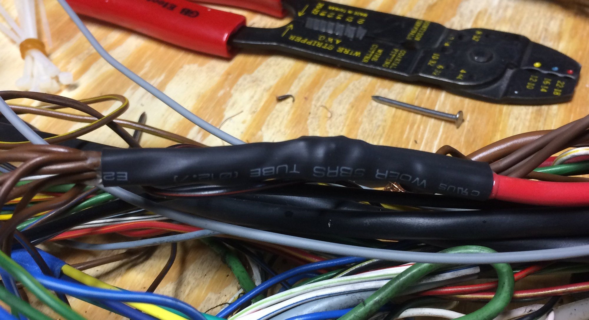
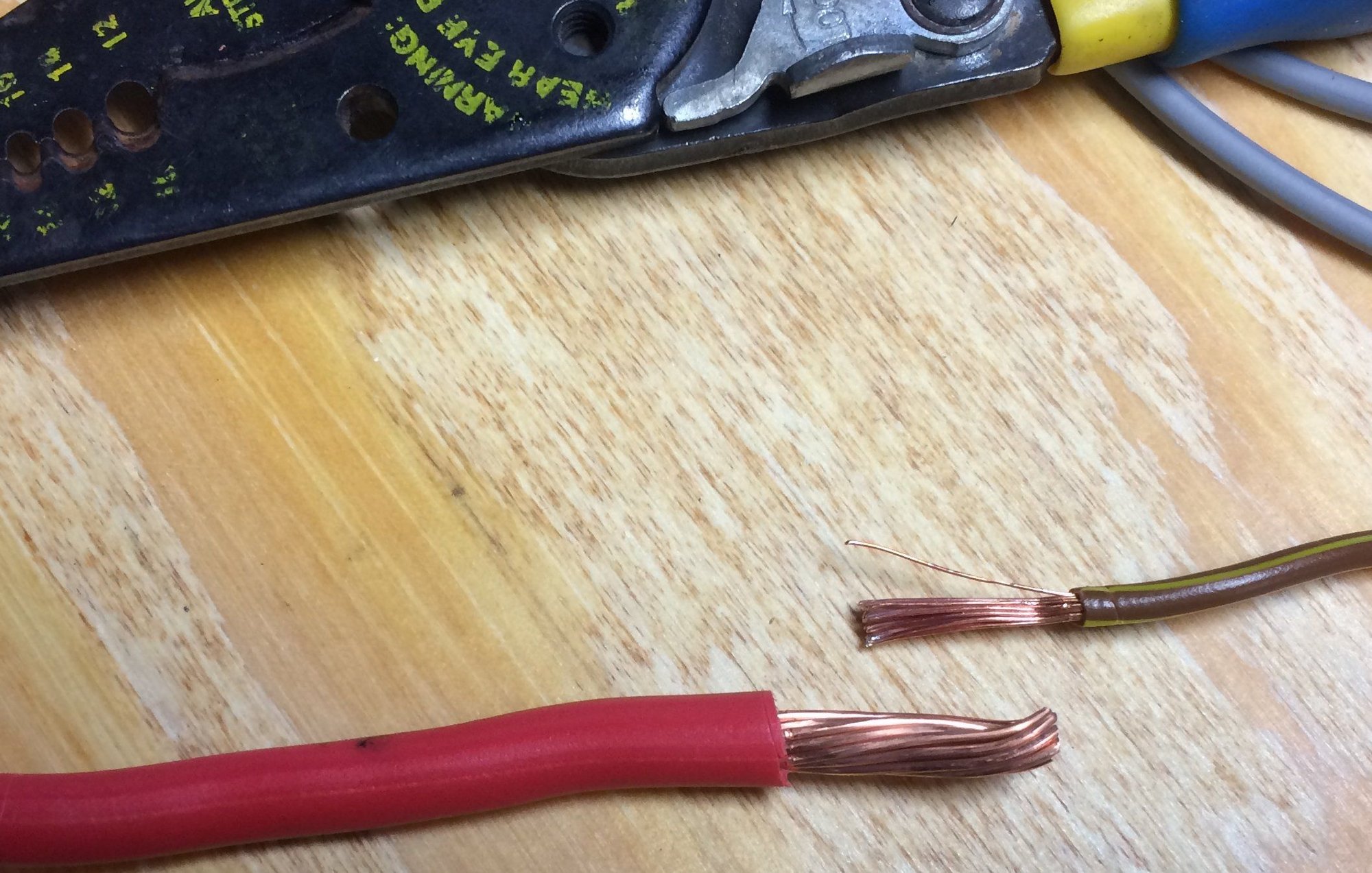
Decided to replace the two large brown ground wires. I just went to the local car quest and found some wire that was the same gauge. However they had thicker strands so it was a bit tougher to solder together with the fine wires (red and brown wire photo). Not really sure how Porsche got theirs together (photo of all brown grounds). They had some sort of square press and bonding agent....doesn't look to be soldered???
If I did it over, I would have ordered some fine strand 10 gauge (I think its 10?) wire from Amazon because I couldn't find it locally. Trying to bundle all the wires together to solder was challenging. The picture doesn't do it justice, the red cable is pretty stiff. Keeping the set up like stock required 11 wires soldered together.
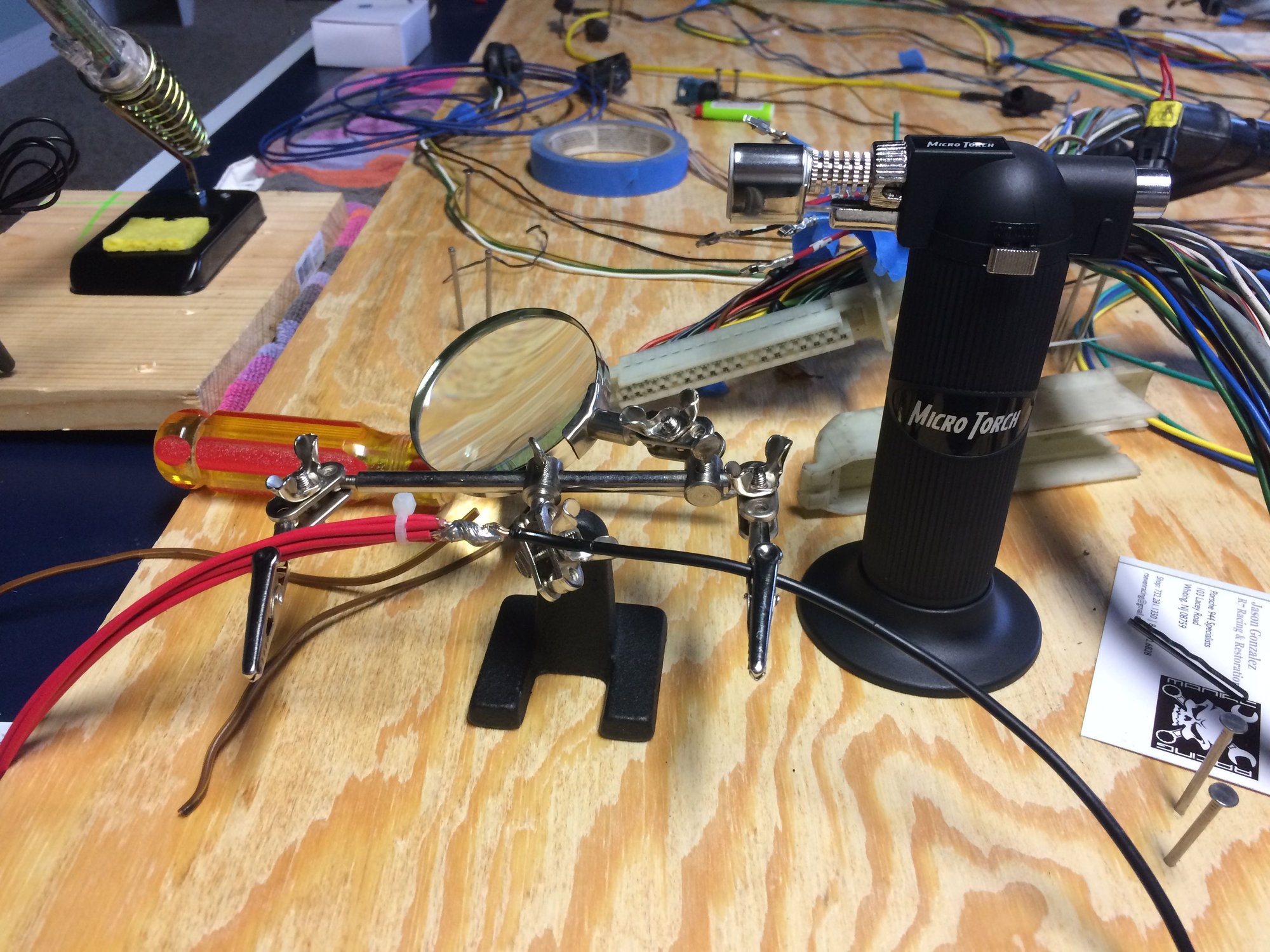
I messed around with a soldering iron, and after several failed attempts went and purchased the harbour freight torch. This thing worked great for the several large bundles and for the heat shrink. Screwing around with a lighter for marine grade heat shrink sucks.
Also, The speed, reference, and Knock sensors are all shielded. I couldn't find any shielded cable without buying "500 ft" so I decided to order them versus making my own.
finally using my ping pong table for something. Unlike many pristine photos of projects posted here to give you inspiration.....I posted my mess to give people hope
Now I'm just waiting for the female pins and techflex to arrive.
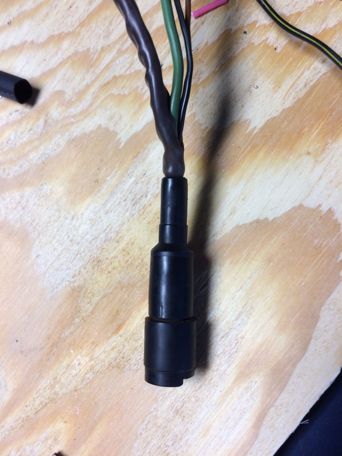
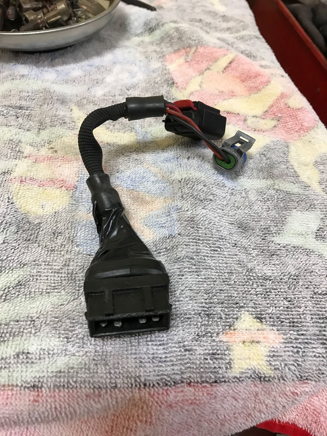
Need Advice....I'm 90% done with this project. I have replaced every wire that runs into the engine bay. My question is the oxygen sensor. is the green thick wire shielded? Those who have done this have you replaced it?
I assume if I cut the rubber boot off the sensor plug I could get to the pins and reuse them with new wire. Is this true? Wanted to ask before I cut this apart.
Its not a huge deal as I don't even have the o2 sensor connected on the car but I just want to the harness to be 100% refreshed should I ever sell it or go back to a stock setup.
This comes from training from my work where soldering is done to NASA and or J standard.
When you solder the wires together don't twist them together. Tin each wire first then place them beside each other then solder together.
Tinning just means take a wire with flux on it, heat it up with the heat source and then melt a small amount of solder on it.
Once you have "tinned" the individual wires then place the wires together oriented how you need them, heat both together and solder together with a small amount of solder.
Your pieces will be fine that you have done but it's a cleaner job when you don't twist together. Twisted wires will fail inspection.
I posted a pic on one of the threads of a J standard technical book from my work for a reference.
The green wire is shielded. The shielding connects at DME terminal 23 and runs to the O2 sensor connector, but does not make an electrical connection there.
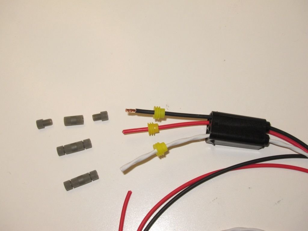
I replaced the all the wire in this circuit. For the shielded wire I used 20AWG dual wall aircraft wire with Tefzel jacketing (available here).
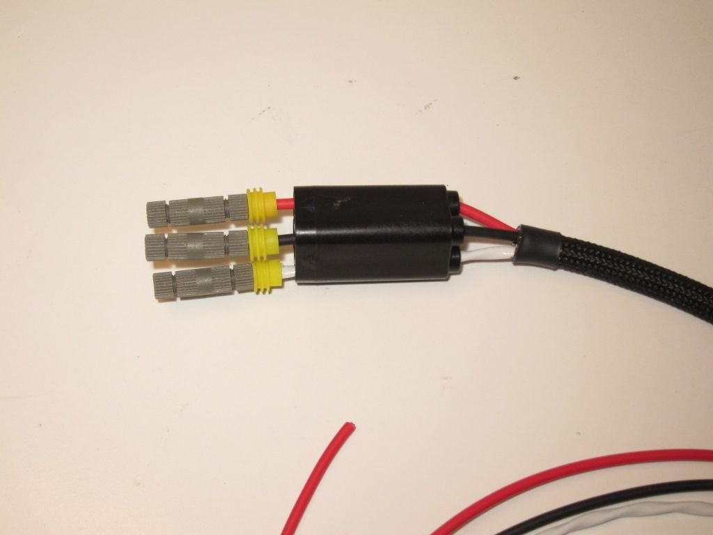
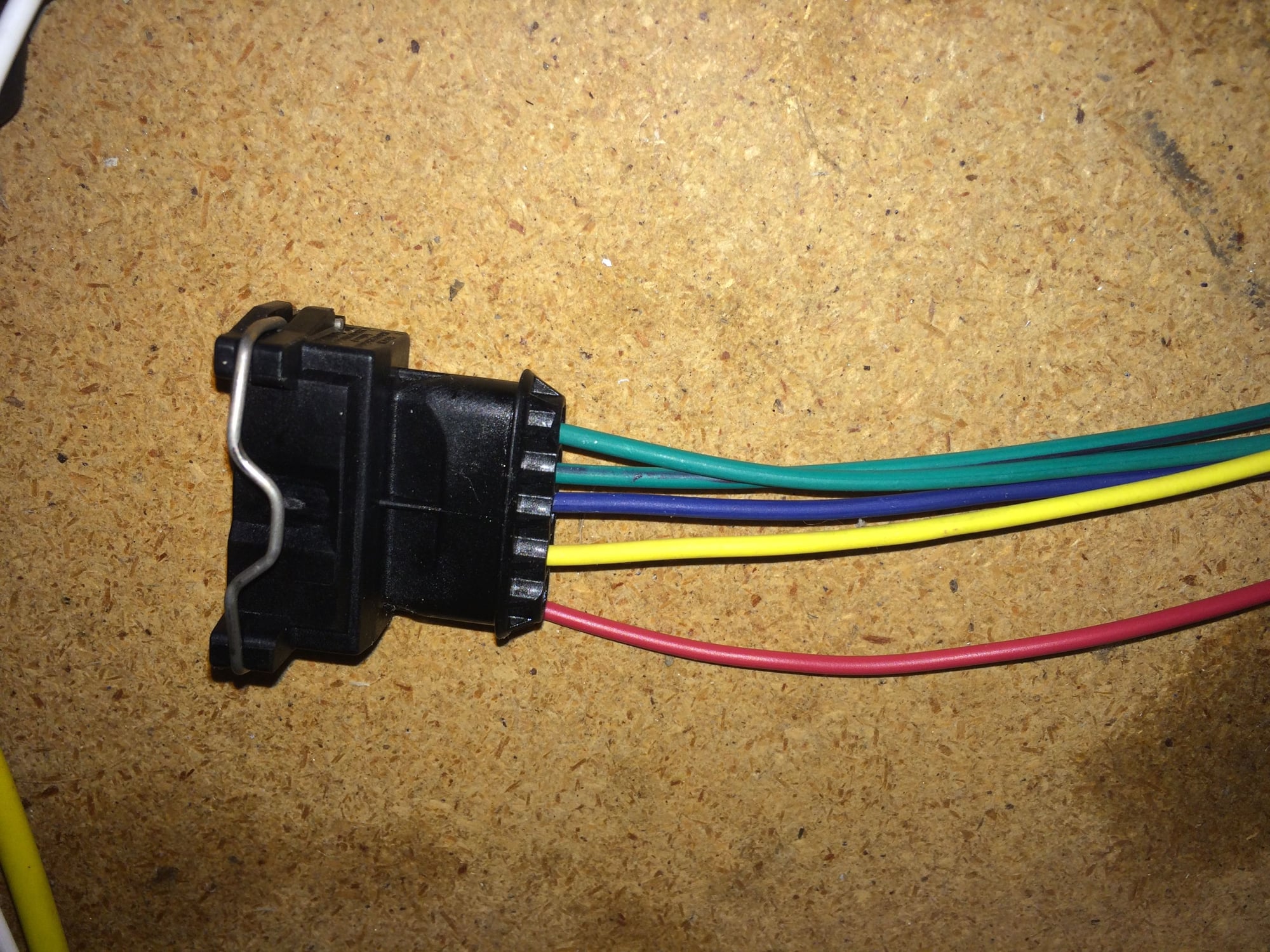
Locating a replacement O2 connector for the harness proved difficult. Rather than fuss with the original connector, I switched to using an O2 sensor with a universal connector. These use threaded barrel connectors to electrically join the wires without soldering (which is important for the O2 sensor, since it gets reference oxygen from the air that enters along the strands of wire).
The plus of this approach is that the O2 sensors with universal connectors are somewhat cheaper. The downside is that it takes a little longer to fully disconnect the harness.
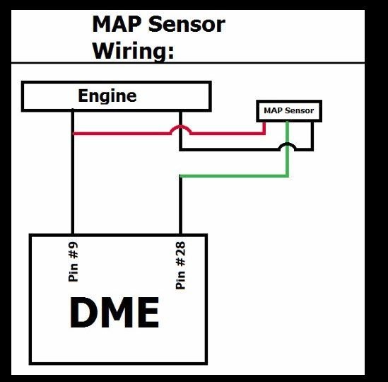
May seem like a dumb question, but I'm getting harness prepared to accept M-tune MAP sensor. it shows cutting wire 28 (which is a ground).
Attach Green wire to DME Side of wire 28 and black wire to "engine side" of wire 28. My new Reference sensor kit eliminated wire 28. So I'm attaching the green wire to pin number 28, and the black wire will go to "engine side" which is just the engine ground.
Is this correct? Guess I'm just not quite sure how the MAP sensor signal uses the ground.
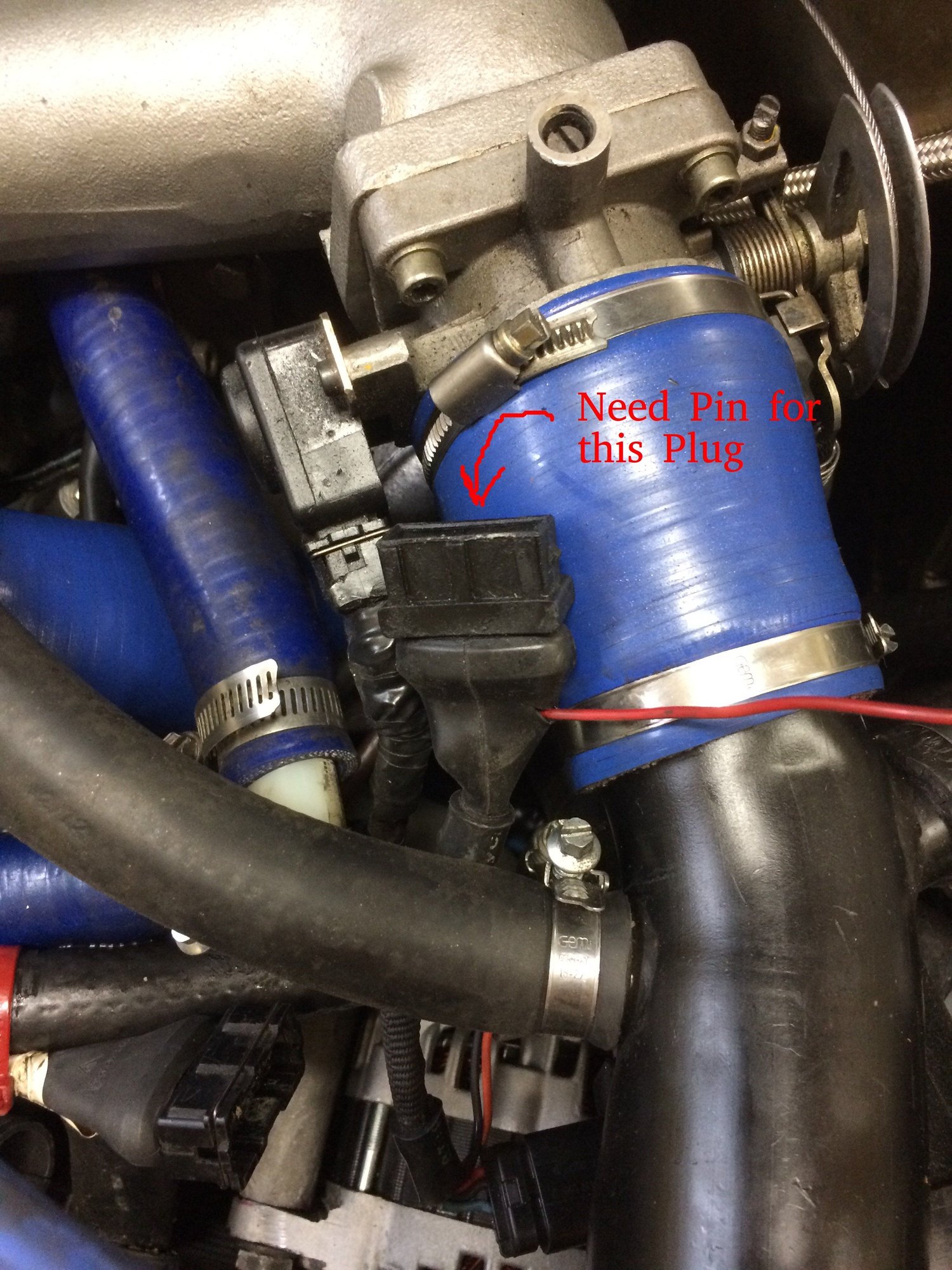
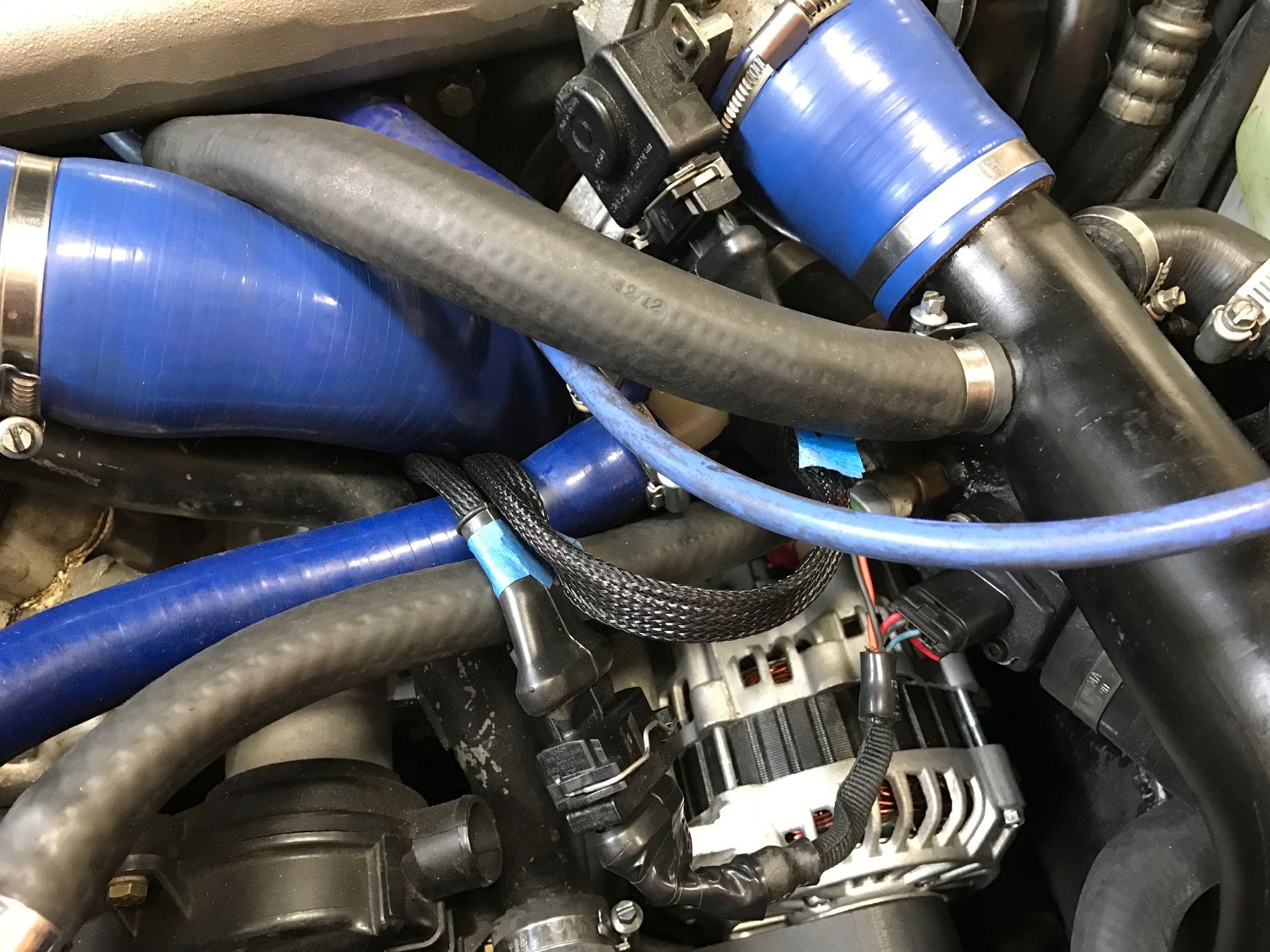
Harness tip - if your running M-tune. A nice enhancement to the harness is to add a 12V circuit to the air flow sensor so you don't have to find a location for the red power wire. The air flow plug has 5 pins but only four are used. Just need to find the male pin for the M-tune plug.
The black wire on pin 28 is GND only on the engine side. Once you cut that wire the DME side is no longer grounded and becomes the input path for the MAP signal (green wire).
Don't forget there's also a resistor on the DME circuit board that must be removed in order for the MAP signal to work correctly.
Success! New harness is in and car fired right up. Nice feeling knowing I wont have to mess those annoying spring clips ever again.
Not a lot of tips to add other than the M-Tune 12 V source mentioned earlier. Added that to the air flow plug to eliminate random red wire running to it. The red wire in the first pic is the one I added and Lindsey Racing was able to supply a male pin for the M-Tune plug
I ended up replacing every wire so I would have complete (stock) harness in the engine bay but what do people think about the test plug.
If I did it over could you just eliminate that. Since I have my old harness, I might rebuild it for this engine set up. (Then there may be a 1 year old refreshed stock harness for sale
Thinking of things to eliminate.
Cycling valve wires
test plug
turbo water switch ( or whatever its called)
oil level sensor (don�t have one)
Also, even though I tried to match lengths, I ended up with what seems like a lot of extra length of wire in the engine bay, especially on the reference sensors and knock sensor. I bought those since I had a hard time finding shielded cable. I may end up pulling boot at the fire wall loose again and pulling the extra wire back to the inside of the car to clean things up.
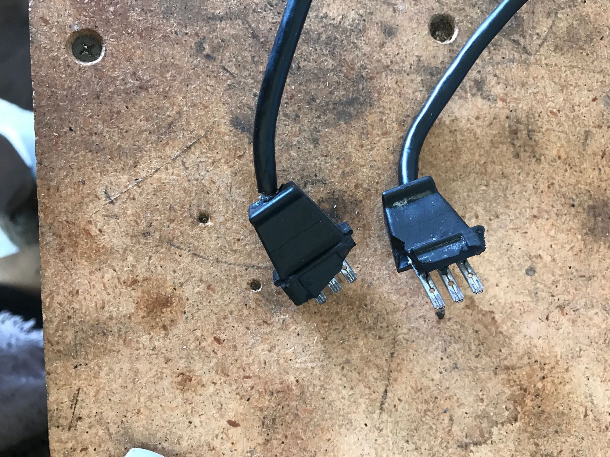
Replaced sensors since the plastic was all but gone. I had them taped together and they haven't been apart for 10 years.


 12-12-2016 | 02:59 PM

 and I wish I would have waited for your reply...I went razor blade and patience. Quite a process just to get it stripped.