
TonyG > New Race Car Build Thread
 05-23-2013, 01:13 AM
#601
Three Wheelin'
Hi Tony, that sucks!
Here's an idea... given that the sway bar is // to the rack:
Onto the adapter, weld a forward-facing arm that has a clevis-like end (like a crab claw, can't remember the right word), lined with UHMWPE, that locates over the sway bar. This would stop the rack from rotating.
Not elegant, but would work!
Cheers,
Mike
 05-23-2013, 12:49 PM
#602
Addict
Rennlist Member
Rennlist Small
Business Sponsor
Rennlist Member
Rennlist Small
Business Sponsor
Anything you can do the raise the rack and lower the attachment point to the spindle will help (then you can shorten the adapter height). Moving the rack forward will help a little - but not enough to solve the problem by itself.
Or you could just raise the ride height of the car by 2-3".....
Or you could just raise the ride height of the car by 2-3".....
05-23-2013, 11:12 PM
#603
Rennlist Junkie Forever
Thread Starter
Over my dead body!
Fortunately the front uprights have the spindle location in relationship to the control arm mounting point raised considerably from that of a regular GT3.
This will allow us to get away without the adapters once we move a few things around.
TonyG
Fortunately the front uprights have the spindle location in relationship to the control arm mounting point raised considerably from that of a regular GT3.
This will allow us to get away without the adapters once we move a few things around.
TonyG
05-24-2013, 12:33 AM
#604
Burning Brakes
Join Date: Nov 2007
Location: Nuke City, NM
Posts: 872
Likes: 0
Received 0 Likes
on
0 Posts
Hmm, that's a tough one. I'm sure they'll figure out an appropriate solution. I'm surprised things have gone so smoothly for them this far...says a lot about the capabilities of the shop!
05-27-2013, 11:59 PM
#605
Pro
Join Date: Nov 2001
Location: Charlotte, NC
Posts: 549
Likes: 0
Received 0 Likes
on
0 Posts
Tony, your dual fuel cell setup is really clever. I like it a lot and it looks like something I might want to consider in a future race car build. However, as I look at how it is setup, some questions come to mind that you have probably thought about:
1. From what I recall, the small fuel cell over the transmission is your surge tank and all fuel going to the engine will be pulled from this small tank, right? And, you have a pump that will transfer fuel from the big main fuel cell to the small surge cell. Therefore, you could have had the refuel line from the dual dry break connections run only to the big tank and allow the small tank to be filled by the transfer pump. But, instead you have a Y connection to enable both tanks to be filled from the dual dry breaks. I am assuming this was done to enable you to fill the entire system relatively quickly, but my guess is for most races, you could fill the tanks at the beginning of the race and not have to refuel again. My only thought was maybe the system didn't need the Y connection (just refuel the big tank) and you would depend on your transfer pump to keep the surge tank full.
2. When you are running sprint races and are "short filling" the tank, how will you determine how much fuel you have consumed (or how much fuel is remaining in the tanks) between races / run sessions?
3. With your dual dry break setup, one line is the "fill line" and the other is the "vent line". Do you have to mark the dual dry breaks on the fuel jugs you will be using to refuel the car to make sure the fill line from the fuel jug matches up to the fill line into your fuel cells?
Thanks,
Jeff
05-28-2013, 12:23 AM
#606
Rennlist Junkie Forever
Thread Starter
Tony, your dual fuel cell setup is really clever. I like it a lot and it looks like something I might want to consider in a future race car build. However, as I look at how it is setup, some questions come to mind that you have probably thought about:
1. From what I recall, the small fuel cell over the transmission is your surge tank and all fuel going to the engine will be pulled from this small tank, right? And, you have a pump that will transfer fuel from the big main fuel cell to the small surge cell. Therefore, you could have had the refuel line from the dual dry break connections run only to the big tank and allow the small tank to be filled by the transfer pump. But, instead you have a Y connection to enable both tanks to be filled from the dual dry breaks. I am assuming this was done to enable you to fill the entire system relatively quickly, but my guess is for most races, you could fill the tanks at the beginning of the race and not have to refuel again. My only thought was maybe the system didn't need the Y connection (just refuel the big tank) and you would depend on your transfer pump to keep the surge tank full.
1. From what I recall, the small fuel cell over the transmission is your surge tank and all fuel going to the engine will be pulled from this small tank, right? And, you have a pump that will transfer fuel from the big main fuel cell to the small surge cell. Therefore, you could have had the refuel line from the dual dry break connections run only to the big tank and allow the small tank to be filled by the transfer pump. But, instead you have a Y connection to enable both tanks to be filled from the dual dry breaks. I am assuming this was done to enable you to fill the entire system relatively quickly, but my guess is for most races, you could fill the tanks at the beginning of the race and not have to refuel again. My only thought was maybe the system didn't need the Y connection (just refuel the big tank) and you would depend on your transfer pump to keep the surge tank full.
The primary tank is in the passenger side (35 gallons). This is the normal tank we'll operate off of.
If we need more capacity, we'll use the rear tank.
The rear tank pumps into the main tank, directly into the surge tank in the fuel cell.
Filling: We have a Y or a straight pipe depending on if we want to fill both tanks or only one tank. What you're seeing is the Y installed.
Dry Breaks: This is not a dual dry break. It's a single dry break. One side is the fuel fill, the other is the vent. The vent must be equal to the fuel fill with respect to size in order to fill with no restriction.
2. When you are running sprint races and are "short filling" the tank, how will you determine how much fuel you have consumed (or how much fuel is remaining in the tanks) between races / run sessions?
Plus... after each race, we have a system to pump out the fuel of each tank. This is important so that you can not only know exactly how much fuel you have in the tank, but for testing so that you can accurately measure fuel consumption.
3. With your dual dry break setup, one line is the "fill line" and the other is the "vent line". Do you have to mark the dual dry breaks on the fuel jugs you will be using to refuel the car to make sure the fill line from the fuel jug matches up to the fill line into your fuel cells?
Thanks,
Jeff
Thanks,
Jeff
In a normal race where quick fill isn't required... we'll just use a jug with a dry break fitting on something to hold open the other side while we put fuel in the pits.
On an enduro race, we'll use a fuel tower with a dual feed with one setup as the supply and one setup as the vent.
TonyG
05-28-2013, 02:17 PM
#607
Pro
Join Date: Nov 2001
Location: Charlotte, NC
Posts: 549
Likes: 0
Received 0 Likes
on
0 Posts
Tony, thanks for your reply. The way you have the two tanks setup sounds great to me and makes complete sense. I am not sure why I was thinking the smaller tank was setup as a surge tank so to speak. I think you had probably written about this earlier in the thread and I forgot. Getting too old . . .
Regarding the analog fuel gauges you have on each tank, are you referring to a "dip stick" in each tank? Or, do you actually have an analog fuel level sender in each tank that can send an electrical signal to a gauge on the dash?
Your idea to pump out the fuel between run sessions is a good one because that will enable you to very reliably determine what really is (or isn't) in the tanks.
Regarding the vent system for both cells, clearly each cell is plumbed into the dry break vent line connection which provides the appropriate vent while refueling. However, is there also a separate vent that enables air to be drawn into the tanks while fuel is consumed when driving the car?
Jeff
05-28-2013, 02:25 PM
#608
Pro
Join Date: Nov 2001
Location: Charlotte, NC
Posts: 549
Likes: 0
Received 0 Likes
on
0 Posts
Regarding the tie rod issue, when I first saw those adaptors, I was thinking they looked like a problem area but I didn't want to say anything because I was hoping they would actually work. The stresses on the tie rods are significant and really need to be fully understood when putting together the front suspension setup.
In my opinion, the tie rods cannot be offset from their connection to the steering rack. In addition, I don't like the single shear ball joint pins to attempt to fix the geometry at the steering arms. The only two alternatives in my mind are:
1. Raise the steering rack (but there is probably no room to do this).
2. Lower the steering arms on the struts preferably without using those extended single shear ball joint pins (it sounds like you are working something to accomplish this alternative).
Jeff
05-28-2013, 03:18 PM
#609
Rennlist Junkie Forever
Thread Starter
Your idea to pump out the fuel between run sessions is a good one because that will enable you to very reliably determine what really is (or isn't) in the tanks.
Without removing the fuel completely to see exactly how much was consumed, you have no real way of knowing.
Regarding the vent system for both cells, clearly each cell is plumbed into the dry break vent line connection which provides the appropriate vent while refueling. However, is there also a separate vent that enables air to be drawn into the tanks while fuel is consumed when driving the car?
Jeff
TonyG
05-28-2013, 03:30 PM
#610
Rennlist Junkie Forever
Thread Starter
Regarding the tie rod issue, when I first saw those adaptors, I was thinking they looked like a problem area but I didn't want to say anything because I was hoping they would actually work. The stresses on the tie rods are significant and really need to be fully understood when putting together the front suspension setup.
In my opinion, the tie rods cannot be offset from their connection to the steering rack. In addition, I don't like the single shear ball joint pins to attempt to fix the geometry at the steering arms. The only two alternatives in my mind are:
1. Raise the steering rack (but there is probably no room to do this).
2. Lower the steering arms on the struts preferably without using those extended single shear ball joint pins (it sounds like you are working something to accomplish this alternative).
Jeff
In my opinion, the tie rods cannot be offset from their connection to the steering rack. In addition, I don't like the single shear ball joint pins to attempt to fix the geometry at the steering arms. The only two alternatives in my mind are:
1. Raise the steering rack (but there is probably no room to do this).
2. Lower the steering arms on the struts preferably without using those extended single shear ball joint pins (it sounds like you are working something to accomplish this alternative).
Jeff
As far as the rack goes.... it's not going anywhere. It's already 1/8" from the bottom of the pan.
They were deciding on the lower control arm mounting point vs the control arm length (it's adjustable) in terms of the fix... as of last week.
TonyG


 06-15-2013, 12:52 AM
#612
Rennlist Junkie Forever
Thread Starter
6/14/13 update
Back on the project. Been finishing up a ton of details.
Throttle cable, fuel system, fuel filler, transfer pump, battery box, ecu box, dash fitment, obtain and fit Racepak IQ3 logger dash and Smartwire, Vnet sensors install, new gas pedal, and a ton more.
The small crap just doesn't end.


After looking in great depth at Motec and AIM for a digital dash, data logger, and sensor input condition output setup, AIM is out of the question as it has no real conditional outputs and a very limited number of inputs. And it's not on a CAN Bus. No go. Motec has everything, but the CDL and SDL just don't have the inputs/outputs and the PDM won't work with the CDL or SDL except for exhaust thermocouples.. which I don't need. So with the CDL and SDL not being expandable, that just leaves the ADL3. And it's just way too expensive when combined with a PDM 30/32.
So for less than 1/2 the price.... I can get the Racepak IQ3 logger dash (with 2gig of mem vs Motec with a measly 4/8/16/120mb... and BTW.... 16mb on Motec is $1800!!!!! GULP).


And I'm running the new Racepak Smartwire (the equivalent of the Motec PDM).
So the entire cam will be run on a CAN Bus with the Smartwire controlling every aspect of the car. No fuses. No relays. Fully programmable. Very nice stuff for sure.
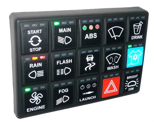
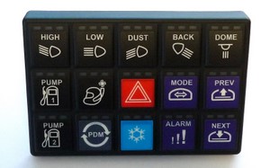
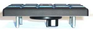
And to top it off.... to do manual switching, I'm reverse engineering the CAN Bus protocols to allow me to use the RaceGrade Motorsport Keypad with the Smartwire to perform manual switching which also has a 0-3 status (4 position status feedback light per switch). Super trick.
No typical race car dash full of manual switches.
See here:
TonyG
Back on the project. Been finishing up a ton of details.
Throttle cable, fuel system, fuel filler, transfer pump, battery box, ecu box, dash fitment, obtain and fit Racepak IQ3 logger dash and Smartwire, Vnet sensors install, new gas pedal, and a ton more.
The small crap just doesn't end.
After looking in great depth at Motec and AIM for a digital dash, data logger, and sensor input condition output setup, AIM is out of the question as it has no real conditional outputs and a very limited number of inputs. And it's not on a CAN Bus. No go. Motec has everything, but the CDL and SDL just don't have the inputs/outputs and the PDM won't work with the CDL or SDL except for exhaust thermocouples.. which I don't need. So with the CDL and SDL not being expandable, that just leaves the ADL3. And it's just way too expensive when combined with a PDM 30/32.
So for less than 1/2 the price.... I can get the Racepak IQ3 logger dash (with 2gig of mem vs Motec with a measly 4/8/16/120mb... and BTW.... 16mb on Motec is $1800!!!!! GULP).
And I'm running the new Racepak Smartwire (the equivalent of the Motec PDM).
So the entire cam will be run on a CAN Bus with the Smartwire controlling every aspect of the car. No fuses. No relays. Fully programmable. Very nice stuff for sure.
And to top it off.... to do manual switching, I'm reverse engineering the CAN Bus protocols to allow me to use the RaceGrade Motorsport Keypad with the Smartwire to perform manual switching which also has a 0-3 status (4 position status feedback light per switch). Super trick.
No typical race car dash full of manual switches.
See here:
TonyG
06-15-2013, 11:06 PM
#613
Rennlist Member
Looks great. You're not wrong about all the small stuff taking up time...and time = $. Your car would cost way over $100k to build down here. Maybe double. Lucky you must be getting great labour rates!
06-16-2013, 12:48 AM
#615
Drifting
Join Date: Aug 2009
Location: Bangkok, Thailand, Milpitas, CA & Weeki Wachee, FL
Posts: 2,239
Likes: 0
Received 2 Likes
on
1 Post
Awesome work Tony! This is truly a thing of beauty and from what I see $100K for all that custom work is still a good deal. Can't imagine there are any 951 based race cars as well sorted as this one. I guess the ultimate proof will be found out on the track.