
busy weekend, twin scroll vs stock crossover data, maf voltage etc
 05-08-2011, 10:40 PM
#1
Race Car
Thread Starter
Ok so I finally got time to sort some things out and collect some data regarding the twin scroll and stock crossover pressure measurements. During this time I measured the MAF voltage (Ford Lightning MAF) to log the airflow differences.
Parts: HX 35 with a t4 .48 hotside, fairly stock engine on E85.
Initially (couple weeks ago) I also had a leak in the vacuum line going to my BOV so the turbo was working overtime and creating more crossover pressure. When this was happening I had close to 60 psi at 20 psi MAP. I even saw 50 psi at 15 psi MAP. The max voltage I saw out of the MAF at that point was less than 4v. That equated to 315 hp no matter whether the pressure was 15 psi or 25. What this resulted in was a crappy dyno session!!
With that fixed and the twin scroll I was seeing 58 psi at 30 psi MAP. I saw about 52 at 25 psi. NOT good!!! The MAF voltage at 30-31 MAP psi was around 4.3. Basically the highest I could get it to go. without running even more boost.
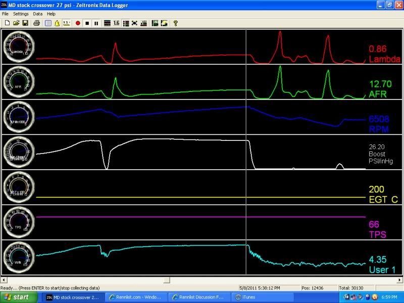
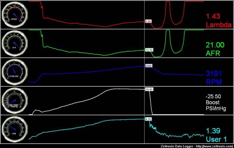
Now I re-installed the stock crossover and started logging. What I saw was 40 psi at 27psi MAP. My MAF voltage was 4.4v and this was even at lower MAP pressure (26psi). That doesn't sound like much but from my understanding regarding the MAF curve the difference between 4.0v(320hp) and 4.3v is a 33% increase in airflow so 4.4 is probably a little more than 420 hp. I'll have to put it on a dyno to verify. It may be far greater or less.
What I do know is that the responsiveness of the twin scroll is better. I could literally rev it in nuetral and make 10 psi free revving. I cannot do that now.
What I have learned is that you can put too big of a pipe between the header and the turbo. What I think happens is the exhaust gas slows down and expands and then becomes more difficult to get through the nozzle of the turbine housing. This was discussed in another thread. In my case the pipes were 2". I will probably reduce the pipe size to a more appropriate size and try it again.
My next step is to add a larger TB along with the custom intake and a larger IC. I will then take a MAF measurement to see what the diffence is. Next will be a Holset HX40 with a .58 open hotside. I may also try to build a larger exhaust in the mean time too.
My goal is to get 4.4v out of the MAF at 25 psi MAP.
PS; I cannot figure out how to do a screen shot off my laptop to show the logs. If I can figure it out I'll post them
Anyway it has been a fun weekend.
Parts: HX 35 with a t4 .48 hotside, fairly stock engine on E85.
Initially (couple weeks ago) I also had a leak in the vacuum line going to my BOV so the turbo was working overtime and creating more crossover pressure. When this was happening I had close to 60 psi at 20 psi MAP. I even saw 50 psi at 15 psi MAP. The max voltage I saw out of the MAF at that point was less than 4v. That equated to 315 hp no matter whether the pressure was 15 psi or 25. What this resulted in was a crappy dyno session!!
With that fixed and the twin scroll I was seeing 58 psi at 30 psi MAP. I saw about 52 at 25 psi. NOT good!!! The MAF voltage at 30-31 MAP psi was around 4.3. Basically the highest I could get it to go. without running even more boost.
Now I re-installed the stock crossover and started logging. What I saw was 40 psi at 27psi MAP. My MAF voltage was 4.4v and this was even at lower MAP pressure (26psi). That doesn't sound like much but from my understanding regarding the MAF curve the difference between 4.0v(320hp) and 4.3v is a 33% increase in airflow so 4.4 is probably a little more than 420 hp. I'll have to put it on a dyno to verify. It may be far greater or less.
What I do know is that the responsiveness of the twin scroll is better. I could literally rev it in nuetral and make 10 psi free revving. I cannot do that now.
What I have learned is that you can put too big of a pipe between the header and the turbo. What I think happens is the exhaust gas slows down and expands and then becomes more difficult to get through the nozzle of the turbine housing. This was discussed in another thread. In my case the pipes were 2". I will probably reduce the pipe size to a more appropriate size and try it again.
My next step is to add a larger TB along with the custom intake and a larger IC. I will then take a MAF measurement to see what the diffence is. Next will be a Holset HX40 with a .58 open hotside. I may also try to build a larger exhaust in the mean time too.
My goal is to get 4.4v out of the MAF at 25 psi MAP.
PS; I cannot figure out how to do a screen shot off my laptop to show the logs. If I can figure it out I'll post them
Anyway it has been a fun weekend.
 05-08-2011, 11:13 PM
#4
Race Car
Join Date: Sep 2005
Location: TEXAS
Posts: 4,247
Likes: 0
Received 0 Likes
on
0 Posts
Ahh..I see. 2" pipe to each side of the twin scroll. (Two, 2" pipes) Lets see. The area of Two 2" pipes is the same as... (googling area of a circle calcutators) a single 2.8" diameter up pipe. I used a 2.5" up pipe. It did well, but the percentage of area from a 2.8" up pipe to a 2.5" up pipe might not sound like much but it's actually pretty large!.. as evidenced.... 2.8" has (6.25 sq. inches) and a 2.5" pipe only has 4.91 sq. inches. for a difference of ... 22% more flow through the 2.8" pipe!!!! - Or in this case, SLOWER flow. Turbo math is fun.
05-08-2011, 11:13 PM
#5
Addict
Rennlist Member
Rennlist Member
Good stuff Sid.
Just for clarification, the comparison was between your custom twin scroll crossover vs. the stock (non-twin scroll) crossover, both with the same turbo, correct?
Just for clarification, the comparison was between your custom twin scroll crossover vs. the stock (non-twin scroll) crossover, both with the same turbo, correct?
05-08-2011, 11:28 PM
#6
Race Car
Thread Starter
Greg yes same turbo.
Bruce, Yeah In hindsight I wish I would have done some better research before building the pipes. It would have been so much easier to use smaller pipes. Lesson learned about assumptions!!
here are a couple screenshots.Nevermind the data on the rh side of one of them as I would not let me add the new image to paint unless I copied it. The little boxes are teh correct data for the curser position
Yes ..I understand it is running lean in the upper rpms. It may be the pump. We are working on it right now.
05-08-2011, 11:34 PM
#7
Nordschleife Master
Ahh..I see. 2" pipe to each side of the twin scroll. (Two, 2" pipes) Lets see. The area of Two 2" pipes is the same as... (googling area of a circle calcutators) a single 2.8" diameter up pipe. I used a 2.5" up pipe. It did well, but the percentage of area from a 2.8" up pipe to a 2.5" up pipe might not sound like much but it's actually pretty large!.. as evidenced.... 2.8" has (6.25 sq. inches) and a 2.5" pipe only has 4.91 sq. inches. for a difference of ... 22% more flow through the 2.8" pipe!!!! - Or in this case, SLOWER flow. Turbo math is fun.
Two 1 3/4" pipes have the same area(ish) as the single 2.5" crossover....
With the HX40, maybe you'll need the extra flow of your larger pipes?? What size is your wastegate? Talking with Josh (I'm sure you've had the same talk with him), a MUCH larger wastegate would probably help your problem as well...
Trending Topics
05-08-2011, 11:39 PM
#8

Ideal gas law applies. Pressure*Volume =nr* Temperature where nr are constants. SO
P=T/V so as V goes up, P goes down with the temp being constant. Lower P, lower turbine speed.
05-08-2011, 11:44 PM
#11
Race Car
Thread Starter
Mark, I'll try it again once I put the other turbo on. To be honest the only way I can see it working would be due to the larger hotside.
It is a 44mm wg. It doesn't seem to be having any boost creep at all with either setup.
It is a 44mm wg. It doesn't seem to be having any boost creep at all with either setup.
05-08-2011, 11:44 PM
#12
Sounds like the paste buffer isn't being cleared. Does it do it in paint too? Do a search on "How To Clear The Contents Of The Clipboard" for the operating system and office package you have. There have been bugs.
05-08-2011, 11:45 PM
#13
Race Car
Thread Starter
05-08-2011, 11:46 PM
#14
Race Car
Thread Starter
05-09-2011, 05:28 AM
#15
Rennlist Member
I think it's just a basic bottle neck in effect Sid.
Thanks for taking the time to do all this and post results.
Pretty sure a larger hotside didn't alleviate the situation for Rod but I'm sure he'll chime in again.
Thanks for taking the time to do all this and post results.
Pretty sure a larger hotside didn't alleviate the situation for Rod but I'm sure he'll chime in again.