

Intake manifold air intake temperatures
 01-14-2008 | 11:09 PM
#16

Addict
Rennlist Member
Rennlist Member
Joined: Feb 2002
Posts: 5,384
Likes: 1
Your number agree with test result from Lindsey racing. Compressed air gets hot.
http://www.lindseyracing.com/mm5/mer...1INTERCOOLER12
http://www.lindseyracing.com/mm5/mer...1INTERCOOLER12
01-15-2008 | 12:02 AM
#17

Rennlist Member
Joined: Oct 2003
Posts: 1,589
Likes: 1
From: Ontario, Canada
Well, the conditions he stated are actually 50 degrees fahrenheit and 2.1 pressure ratio (original post).
I've got a different book that has an exact simple formula and his discharge temps are more like 210 fahrenheit; which would put his IC efficiency at around 55%. That's providing there's minimal pressure drop through the IC.
Using the link, I only seen one pic of the IC. I can't see for sure, but it does seem waaay too small for 3 liter displacement. The internal flow area will also be restricted. So, ya gotta remember in order to get 16 psi boost available to the cylinders, the compressor might be putting out something like 20-22 psi with that pressure drop through the IC. So, that's actually a pressure ratio of 1.4-1.5 (hotter initial discharge temps).
01-15-2008 | 12:24 AM
#18
Burning Brakes
Joined: Feb 2002
Posts: 1,043
Likes: 0
From: Edmonton
Nick, just for some comparison numbers on a very similar setup as yours except TEC3, I showed 40C max temp on a long pull at 200kpa boost. My outside temps were closer to 15C and my temp gauge, a standard GM, is located in the stock boost tube just in front of the throttle body.
From looking at the data log it looked like the temps would have continued to climb even though at a low rate if I had kept accelerating and so it would depend on how long you keep your foot in it as to how hot it gets. That particular run probably took 12 to 16 secs. My intercooler is a Lindsey Stage I, so not optimal by any means. But it seems our numbers correlate pretty closely considering the conditions.
From looking at the data log it looked like the temps would have continued to climb even though at a low rate if I had kept accelerating and so it would depend on how long you keep your foot in it as to how hot it gets. That particular run probably took 12 to 16 secs. My intercooler is a Lindsey Stage I, so not optimal by any means. But it seems our numbers correlate pretty closely considering the conditions.
01-15-2008 | 01:19 AM
#19

Drifting
Joined: May 2006
Posts: 3,481
Likes: 0
From: Melbourne
at what ambient are you seeing 45C? I saw 30 c @ around 20 C so ten above thats was with factory stage 1 cooler bumber cut out and bonnet vents . and at about 21 psi . .
just make sure that through the inter cooler is the easiest path for air to take into the engine bay . so air cant by pass the heat exchangers .
Also I think what you said about air getting through the heat exchangers to easy is absolutely valid . if there is not a nice transition from the duct to the front of the IC air could be rushing through a patch on the inter cooler in the shape of the front duct leaving much of the IC uncooled .
if an inter cooler flows right to left it should be hotter on the right side than the left when you lay your hand on it . but it should be uniform top to bottom
01-15-2008 | 04:39 AM
#20
Pro
Joined: Jun 2005
Posts: 589
Likes: 0
From: Napa Valley, CA
Nick,
According to my thermodynamic calculations,
Starting with:
Ambient Temp of 50 deg F ( = 10 deg C)
Turbo Compressor Effeciency assume = 75%
Pressure Ratio = 2.088 ( = 16 psig)
Intercooler Temperature, IN = 208 deg F (= 98 deg C)
Same as Turbo discharge temp
Intercooler Efficiency assume = 70%
Intercooler Temp. Out = 97 deg F (= 35 deg C)
(same as Manifold Temp)
Ok, so at 45 deg C, your manifold temp. may appear 10 deg C higher than the theoretical or desired temp. However, since it is generally accepted that 15 psig of boost is safe with street octane gas, let�s see how your temp. compares to a �safe� temp.
Let�s see what the intake temp would be on a hot 95 deg F day running 15 psig of boost:
Ambient Temp = 95 deg F (= 35 deg C)
Turbo Compressor Efficiency = 78% (better efficiency at lower boost)
Pressure Ratio = 2.020 (= 15 psig)
Intercooler Temp, IN = 252 deg F (= 122 deg C)
Same as turbo discharge temp
Intercooler Efficiency assume = 70%
Itercooler Temp. Out = 142 deg F (= 61 deg C)
Same as manifold temperature.
So compared to a "safe" 61 deg C, I would say that your 35 deg C manifold temperature ain�t bad at all.
01-15-2008 | 06:00 AM
#22
Pro
Joined: Nov 2001
Posts: 529
Likes: 0
From: UK
Here's a direct link to the pics of Nicks radiator/ intercooler setup
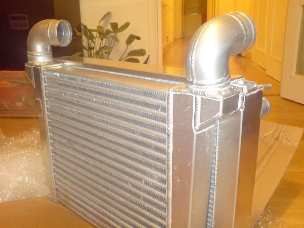
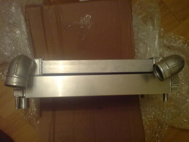
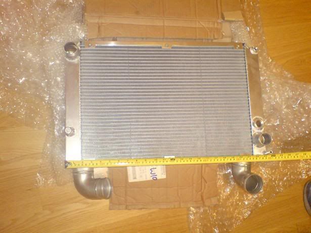
As you can see it is 23" wide by approx 14" deep so it looks plenty big enough.
Nick is there a way to easily move your temp sensor to the hose at the exit of the intercooler? I wonder if the heat from the turbo is affecting things.
As you can see it is 23" wide by approx 14" deep so it looks plenty big enough.
Nick is there a way to easily move your temp sensor to the hose at the exit of the intercooler? I wonder if the heat from the turbo is affecting things.
Last edited by Diver944; 01-15-2008 at 06:01 AM. Reason: typo
01-15-2008 | 06:07 AM
#23
Nordschleife Master
Joined: Aug 2001
Posts: 5,552
Likes: 18
From: Stockholm, Sweden
But the core doesn't seem thicker than about 2".
I would measure pressure before the intercooler and compare with manifold pressure to see the pressure drop. My guess is it's pretty high.
Any pic or more info about where the intake air temp sensor is located?
I would measure pressure before the intercooler and compare with manifold pressure to see the pressure drop. My guess is it's pretty high.
Any pic or more info about where the intake air temp sensor is located?
01-15-2008 | 06:12 AM
#24
Racer
Joined: Apr 2005
Posts: 421
Likes: 0
From: Estonia
I have 100mm*450mm*300mm core + endtanks so overall dimention is 600mm*450*100, running GT35r 1.3-1.4 bar over and I have NEVER seen any temps +10C over ambient.
I have made no changes in the nose panel
http://eku.3lite.ee/albums/album26/P7090065.sized.jpg
My temp sensor is located between the intercooler and throttle body
http://eku.3lite.ee/albums/album26/P7090062.jpg just before the hose starts in TB side.
Nick have you measured your boost pressure befor and after IC?
M
01-15-2008 | 07:55 AM
#25
Thread Starter
Burning Brakes
Joined: Apr 2002
Posts: 782
Likes: 10
From: London, UK
Guys thanks for all the input, really useful. The depth is 2.5 inches as are the inlet/ outlet. I have a restriciton in my 951 IC pipes which are first on the list to be changed out and also the end tank design is poor for flow/ pressure drop. I make the internal volume around 750 - 800 cubic inches on a rough estimate from the dims Paul gave above as I am not near the car right now. I think improving airflow in and out of the IC will be the key. Yes the IC is very close to the rad with a small air gap but the rad is not suffering any cooling probs so I dont see that as a problem, although I will be looking at ways to improve the low pressure zone behind the rad to get better airflow through both IC and Rad.
01-15-2008 | 03:33 PM
#27
Thread Starter
Burning Brakes
Joined: Apr 2002
Posts: 782
Likes: 10
From: London, UK
Been out with the tape measure - depth of core is 2 inches......not enough for good flow I am told. Inlet and outlet on IC is 2.5 inches and the volume of the IC is more like 500 cubic inches. Something tells me the IC will be getting changed.
01-15-2008 | 04:40 PM
#29
Thread Starter
Burning Brakes
Joined: Apr 2002
Posts: 782
Likes: 10
From: London, UK
Thanks Mike, no probs on the quality of my kit either, I just took a chance that it would translate to my application and it did not work out so well as the IC I bought was designed for the ninemeister SC conversion for a 968. It bolts right in but not quite the right size I think. The speedforce does not fit in my car so would have been some extra work, in the end it looks like more customising will be necessary when I have the time and money!