When you click on links to various merchants on this site and make a purchase, this can result in this site earning a commission. Affiliate programs and affiliations include, but are not limited to, the eBay Partner Network.
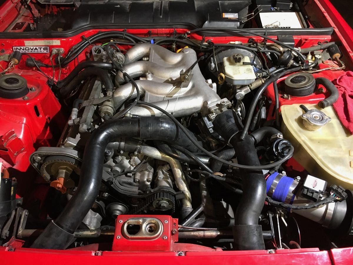
Finally got some 1/4" silicon vaccum hose and I managed to hook up most of the vaccum system and trial-fit most everything tonight.
After mocking up everything I have a few "loose ends"/questions, hope someone have an idea!
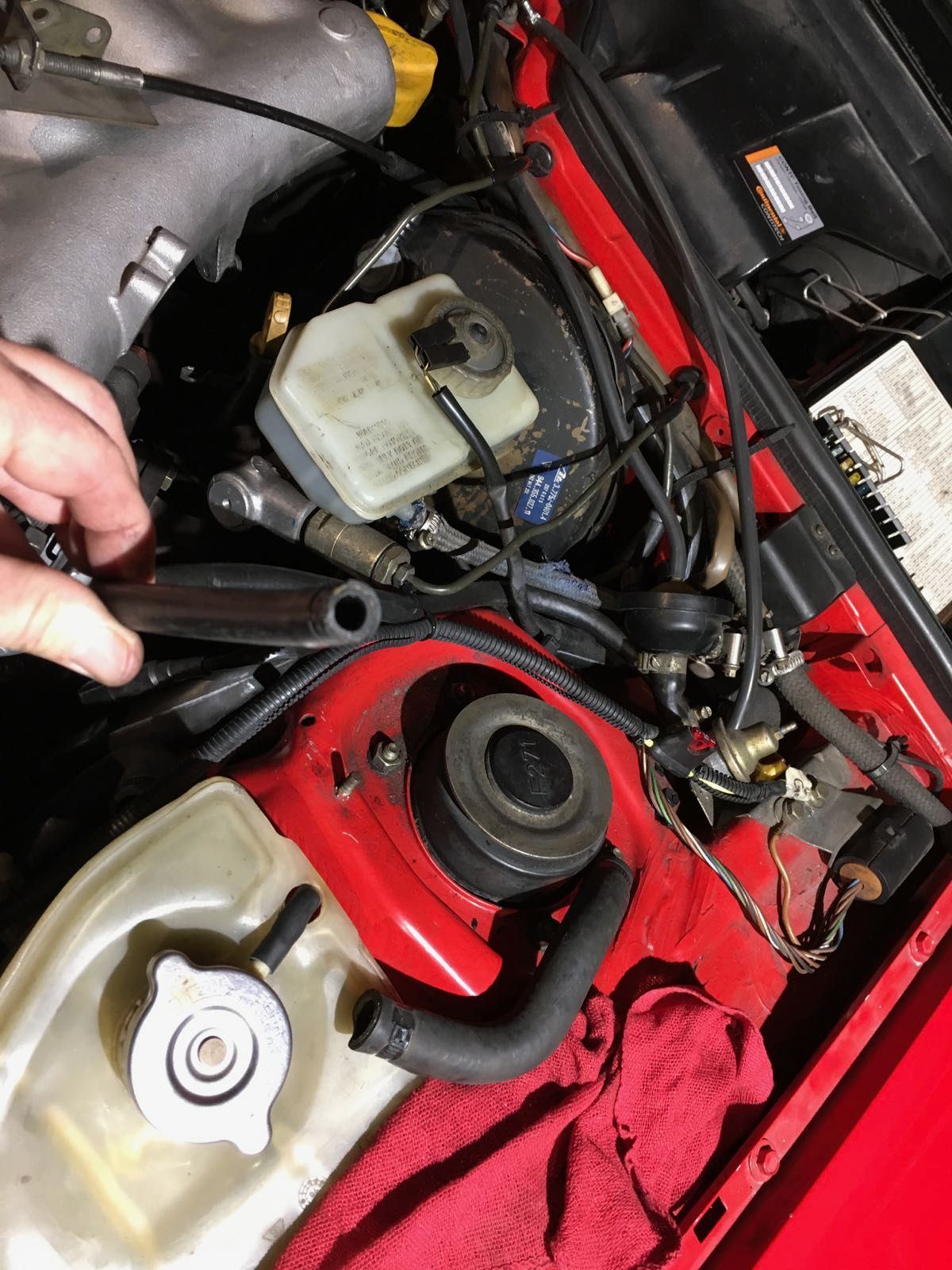
one of the heater /actuator hoses are hooked up, what should I do with the other one?
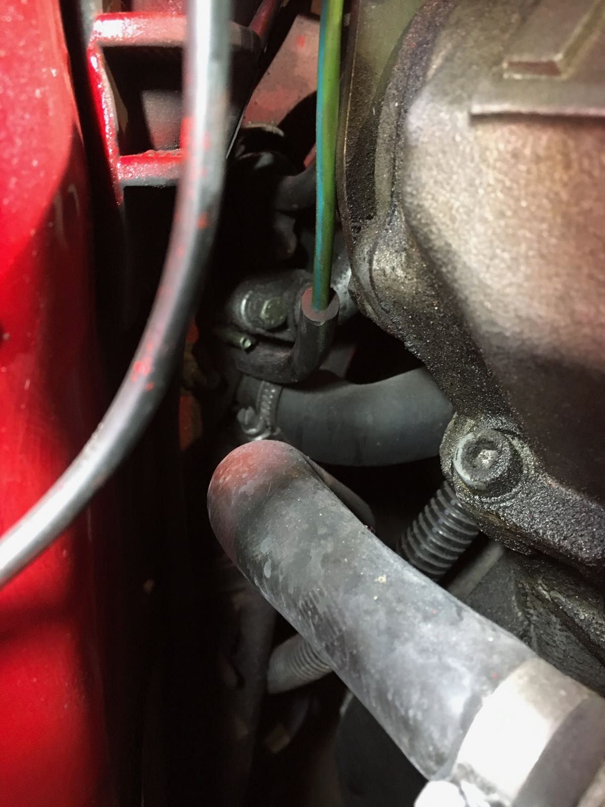
there is a hose coming from the bottom off the fuel vapor stuff up left in the engine ebay, where should it go? Its seem to end almost down aside the turbo.
vacuum canister, just forget about it?
I'll add some text to the photos to possibly explain better.
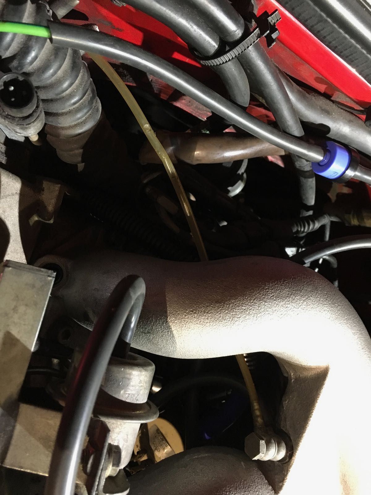
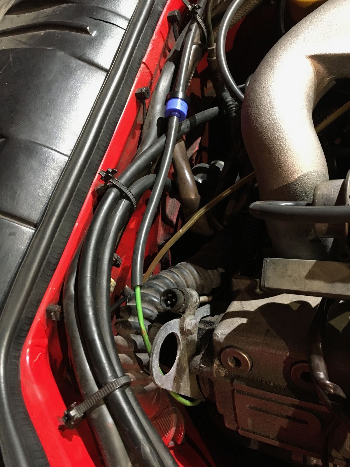
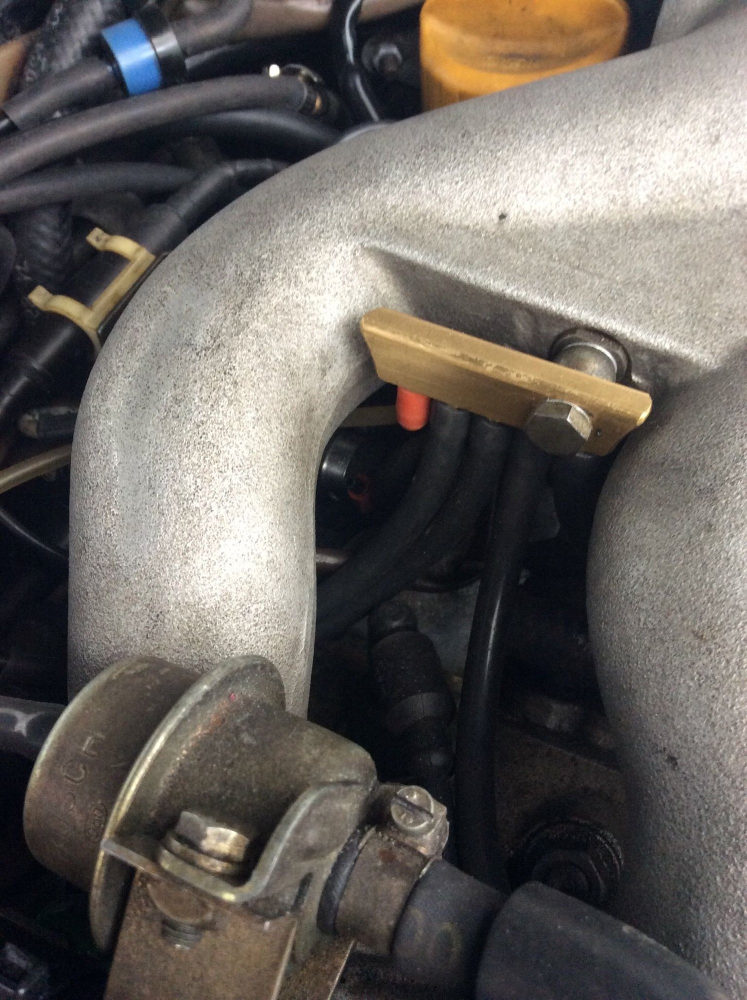
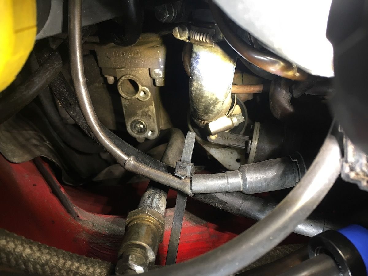
This one is going to one of the two nipples for the heater/actuator, why the blue piece looking like a one way valve (filter?) What to do with the other nipple, connect to vacuum? this is the bottom hose coming from the fuel vapor valve, where does it go? (dec 1986 car) clear line is going to the KLR I suppose, it is getting worn and being swapped or covered with silicon hose. not too bad, fuel vapor and still vaccum to resolve.
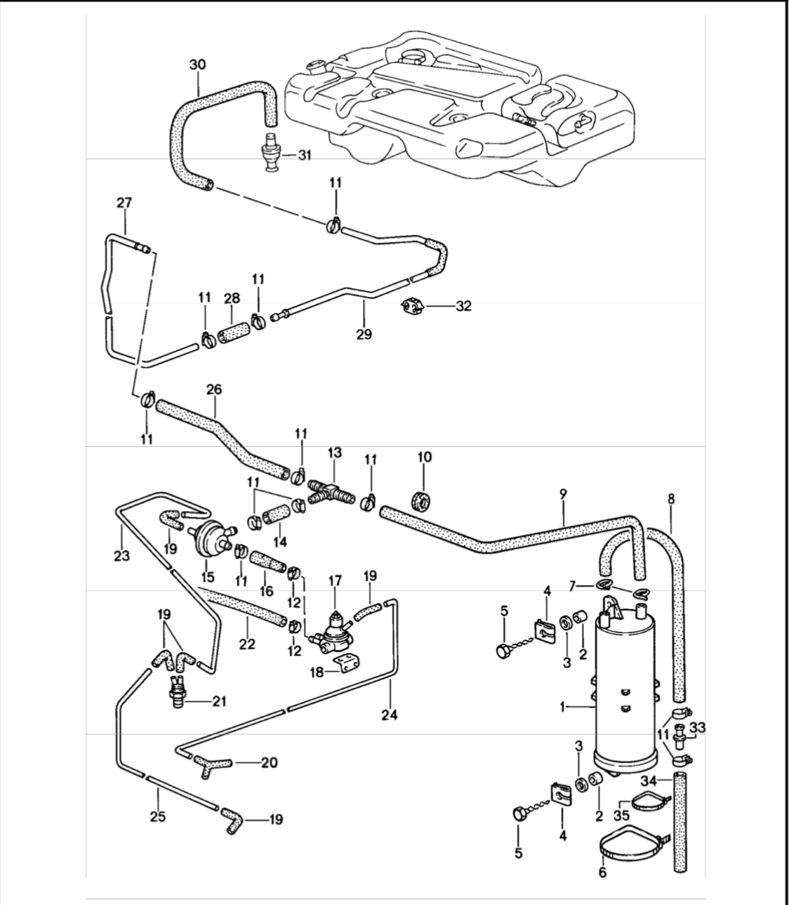
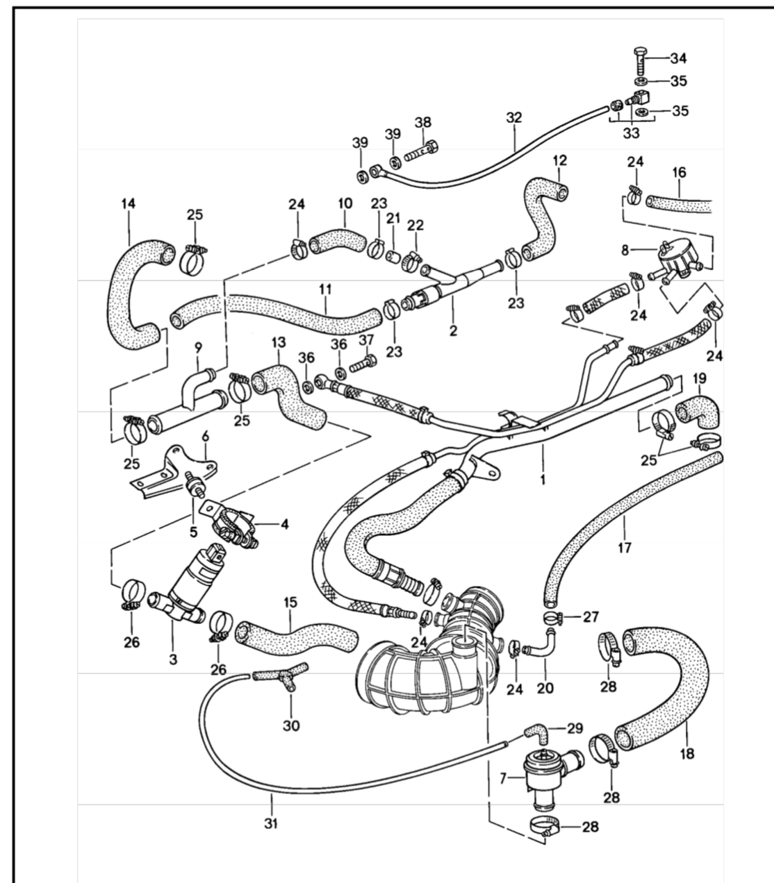
Think I got it now, number 17 in the intake diagram is the same as 22 in the tank diagram. Suppose I will have to use a connector or Y-pipe connect that line into the MAF pipe.
Thanks, havent had time to work on the 951 last weeks but seems like I will get some "garage time" this week. I searched on the Laust vacuum terms but it did not make me wiser
With some luck I hope to fire the engine end of week, I'll just connect the vapor to the MAF manifold for now. I just have to check everything is torqued down, recheck belts, new plugs and then crank it.
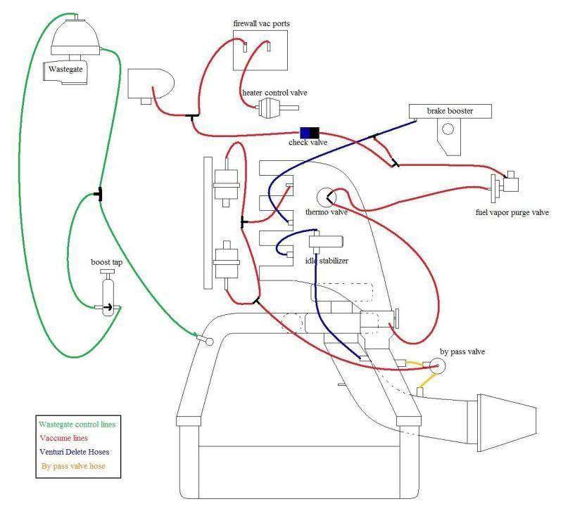
When I contacted Laust little while ago, he had some and I got a 5-port. It's simply one little block you install in place of the vacuum banjo bolt on the intake and it has 4 or 5 nipples to run a vacuum line to each device seperately. Makes installing & diagnosing lines neat and easy.
Notice I have one unused port: perfect for future map sensor or diagnosing with vacuum guage!
OK thanks, I may look into this in the future to cleanup the engine bay further.
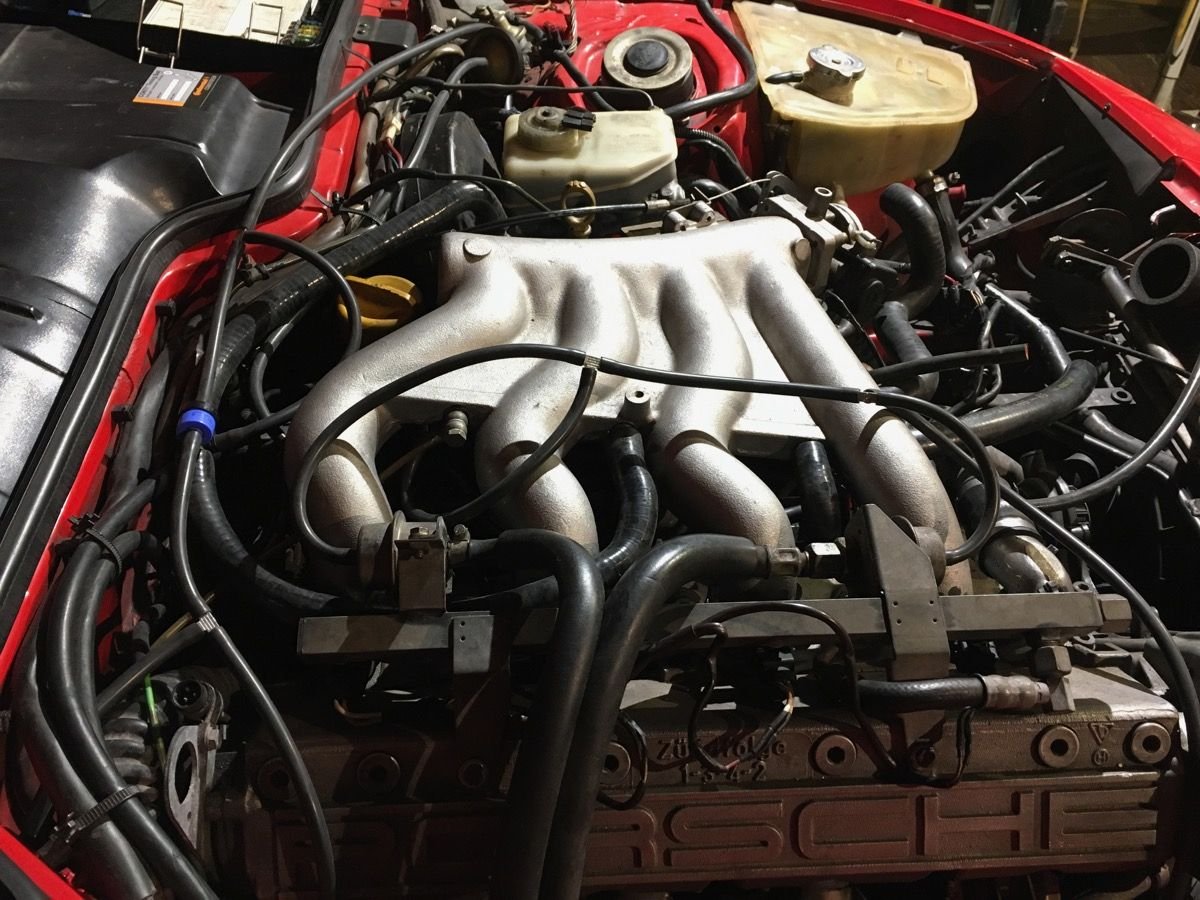
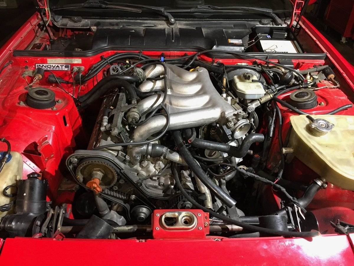
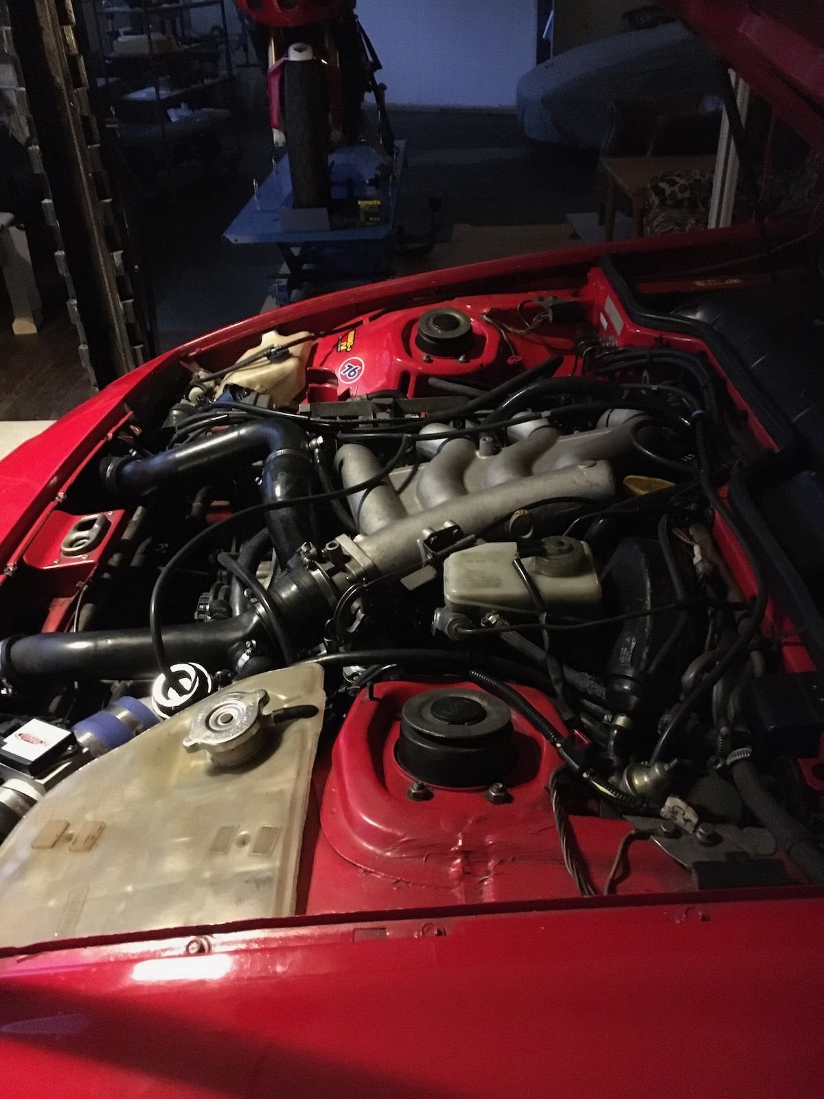
For now most everything is hooked up, it's just the electric turbo cooling pump, distributor and the the intake/MAF to install. Hope to start it end of week.
Another year gone but finally fired up the engine yesterday however it leaked fuel from the press fit supply line and had to stop it after a few secs, at least it fired up.
Left the vacuum line from the tank for now but as soon as I get engine running as it should I'll look into having fabricated something like the "Laust's vacuum block".
Had to jack up the car, remove front wheel and inner fender for the fuel line repair. I found a good instructional at Lindsey racing. Going to check with a local shop that make pressure fit hydraulic/oil lines and have them make a set instead of ordering and waiting.
Thanks, not yet there though. Car still does not start, well it cranks and fires but die immediately.
The old gas had to go, it may be good for the lawn mower but it had this smell and color to it and I decided to empty the tank.
Checked the inline tank screen/filter, very clean, new fuel filter, fuel lines fixed and at the same time I have been installing new seals and those micro filters in all injectors.
All injectors check in at approx 4.8 ohms with my cheapo multimeter, have no way of checking spray patterns but they open as they should.
Removed the resistors I had soldered in as I now use the green OEM injectors, had a vitesse stage 2 turbo kit that was going in but now I have OEM turbo and vitesse MAF.
DME relay checked, not sure if it is good but hotwiring 30-87-87b did not start the car either. Fuel pump running constantly with that mod though, when the DME relay is in the fuel pump only run when I am cranking and then it fire but dies.
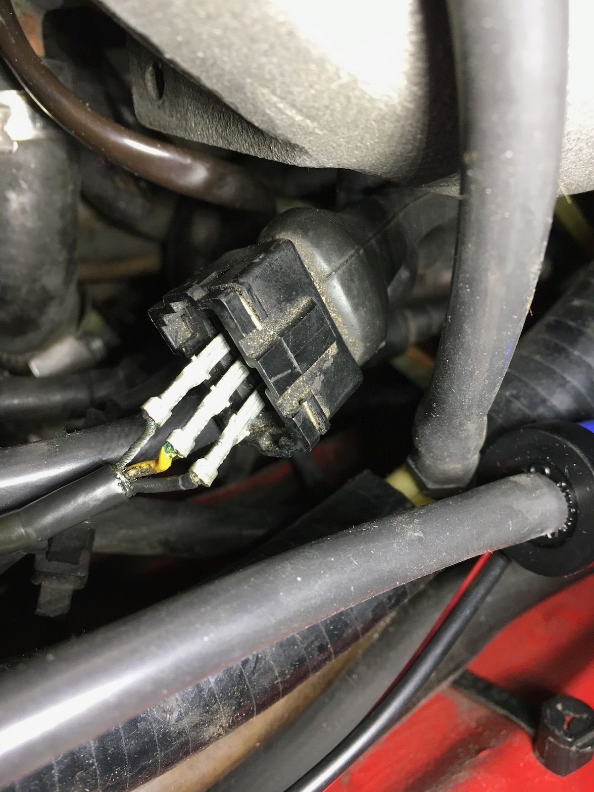
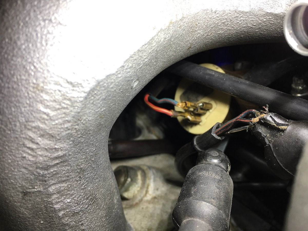
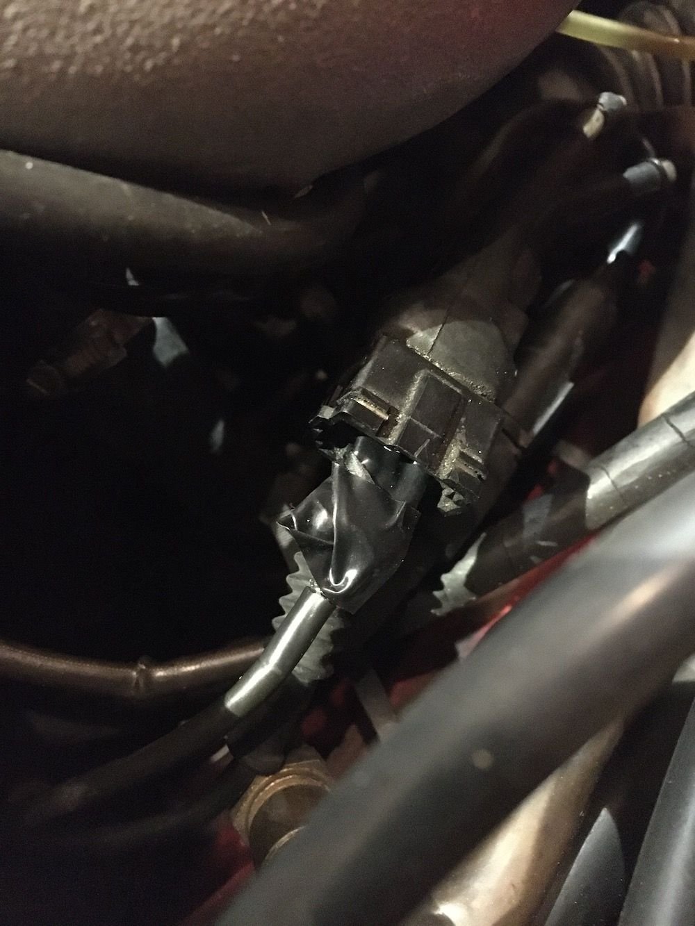
There are a few connectors that are shot but they should not be a problem? The crank position sensor, idle speed valve and cycling valve.
I need to fix the connection to the idle speed valve, the cables are very dry and close to each other with no insulation, cycling valve seems fine with new blades crimped on. I "think" the crank position wires are correct but they were apart for 8 years (?) so maybe not?
"Ran when parked" so hopefully not a DME problem, injector circuit not working maybe but how to test?
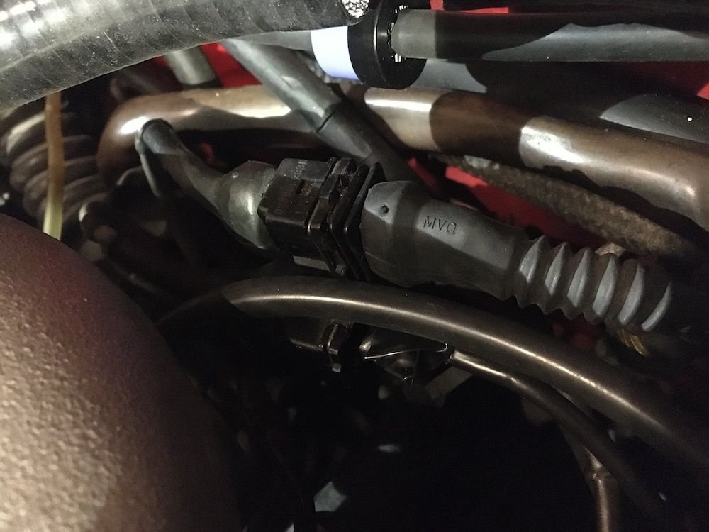
This looks to be correct? Worn harness at the idle valve Vitesse MAF but the rest is OEM now.
Got a new DME relay but did not help, no start just fire and die.
I changed the steering column stalk (for the wipers, lights etc) to a 944 NA stalk a few years ago but should not be anything there right? Immobilizer or similar? Dont think I have run the car after I changed it but thats a real longshot.
Video cranking
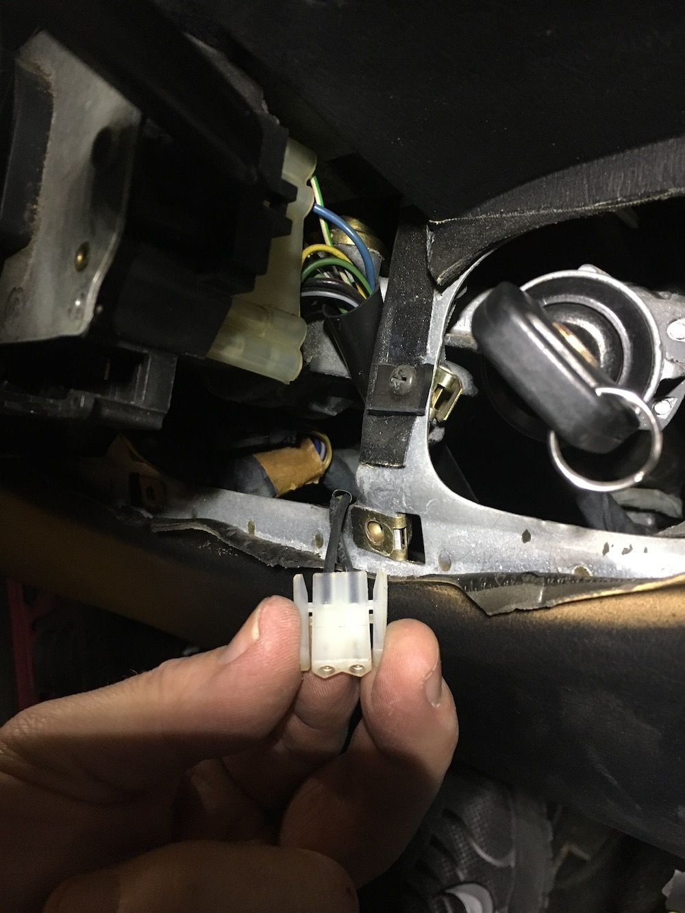
Cant remember where this one go, changed the stalk but dont remember if it was installed there.
Have no idea, just below the steering colums
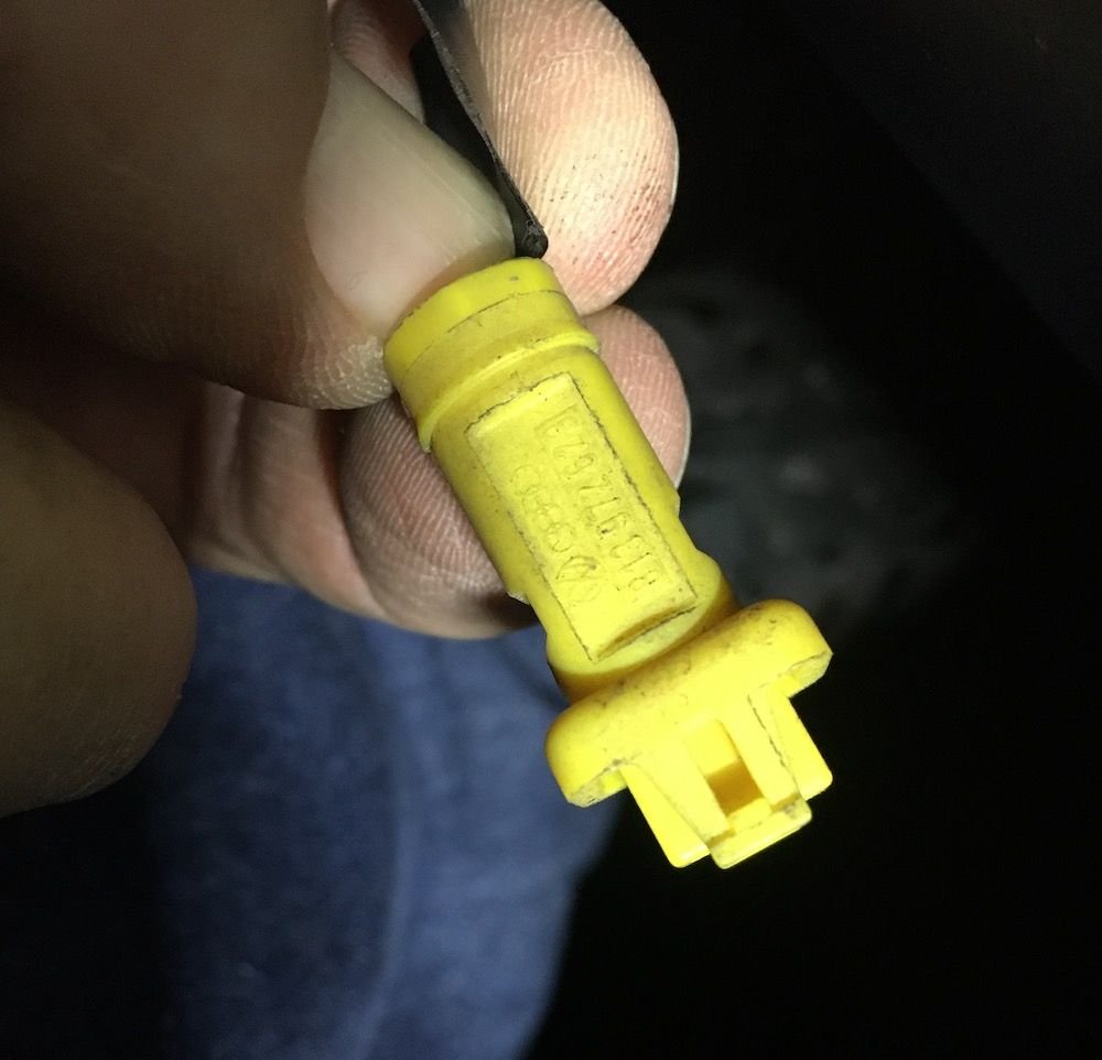
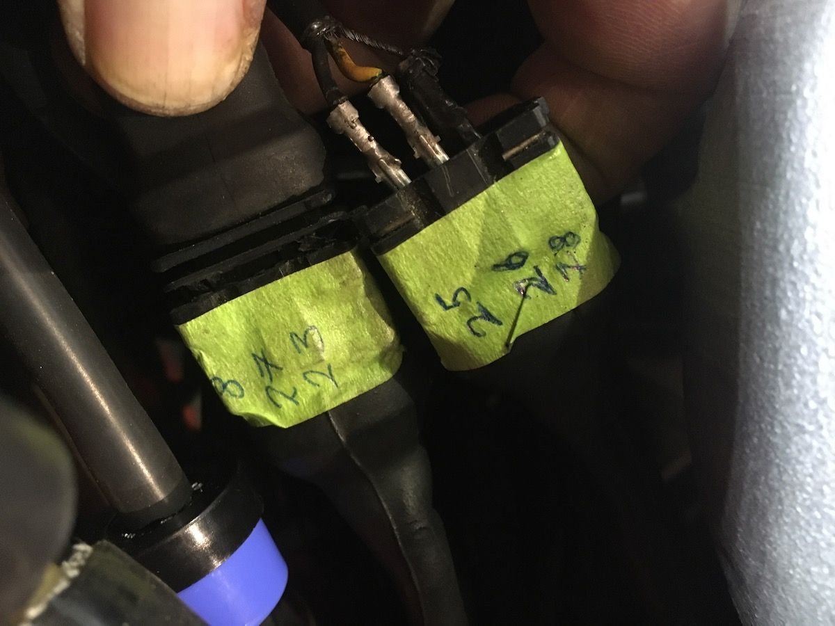
Crank sensor plug, not great but the tacho jump on cranking so it should be good?
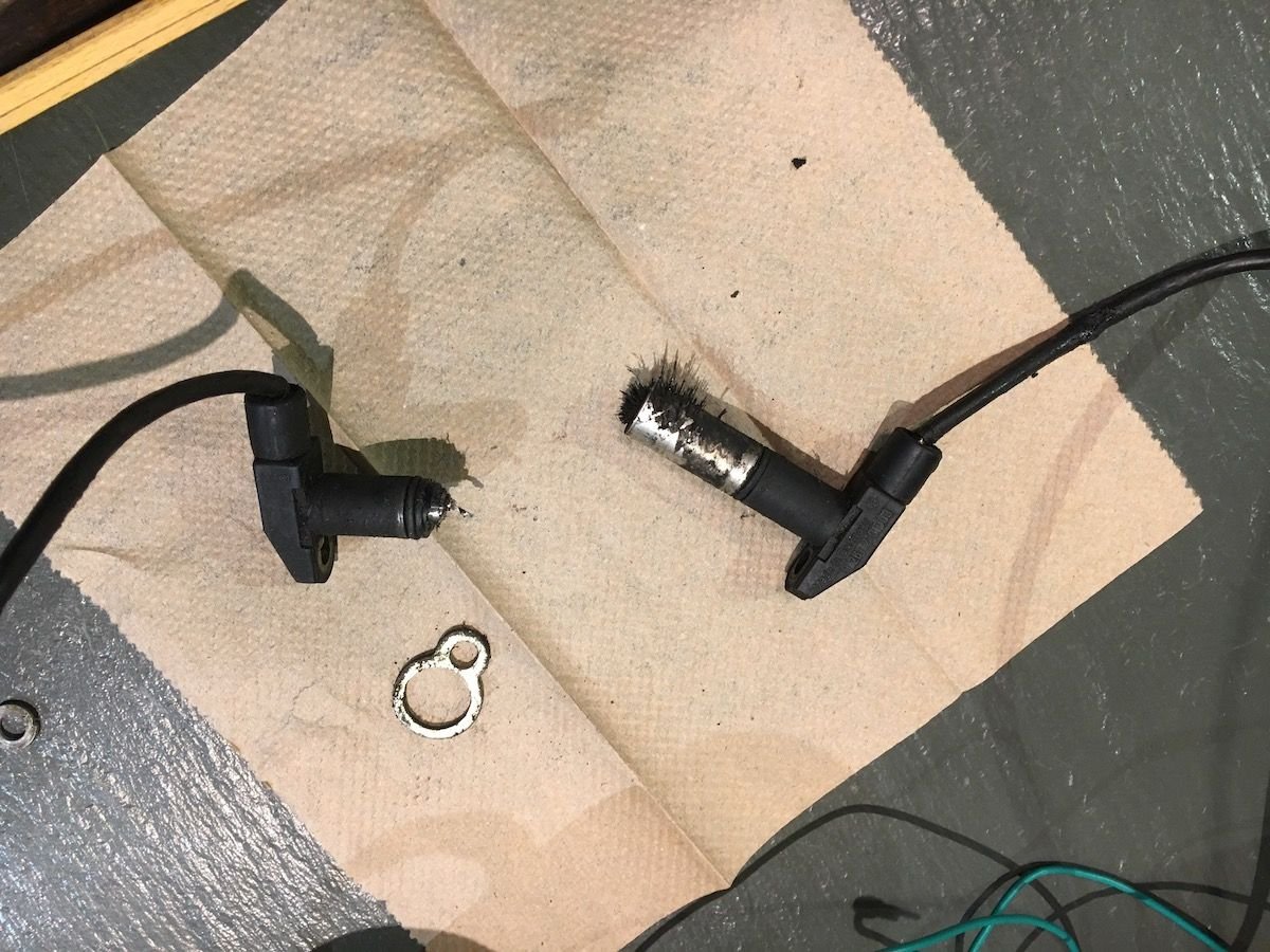
Approaching the sensors.
I went on with the instructions from Clarks garage, first of. I measure the wiring to DME and they were continuous but very brittle. The reference sensor did not get a reading between 25-79 but 25-26 read close to 1K ohm, the speed sensor had the same measure on 8-27 but also +1M Ohms on 8-23.


 10-15-2018, 06:45 PM