When you click on links to various merchants on this site and make a purchase, this can result in this site earning a commission. Affiliate programs and affiliations include, but are not limited to, the eBay Partner Network.
Not sure about the idle - the car was cold when I put the MoMonitor on it. Once I get this hiccup stabilized I will look into the vacuum and idle rpms.
For the moment though, I need some help from all of you. I have a sneaky suspicion that the gap for these sensors is set too far. I remember when I pulled each of the sensors out there was kind of a "ball" of magnetic material stuck to the center of each of the sensors. I wiped all of that ferrous material off and then reinstalled them. It was only after I did that that the car had gotten worse as far as wanting to kill even when it was cold. And so I think the gap is further than it should be. Easy right? Just loosen the two allen head bolts on the sensor bracket, glue the .8 mm washer to the end of the speed sensor, bolt the sensor back into the bracket, push the bracket down as far as it will go and tighten the allen head bolts back up...
That would be easy enough to do if I could get the fricken allen head bolts loose. It literally took me 3 hours of screwing around with different tools just to get the allen wrench into one of the bolts. The space is so cramped and when you have your hand in there - there is no visibility... I finally rigged up a tool to get the 6mm allen wrench into one of the bolt heads (basically it is a drill-bit extension that has set screws in it to hold the allen key but I had to ground down one end of the allen wrench so it would go into the drill bit extension).
Anyway, those bolts are siezed in there! I think I might have bent my allen key just trying to get one to loosen up.
My thighs honestly hurt from bending over the fenders for so long.
So I need some suggestions on how to get those bolts loose. I am at my wit's end here. It almost seems like a guy is going to need to pull the engine out just to get those two damn bolts loose... For now I have dripped some PB Blaster down onto the exposed threads of the back of each bolt as well as around the head/washer of each. I doubt that will do much of anything though.
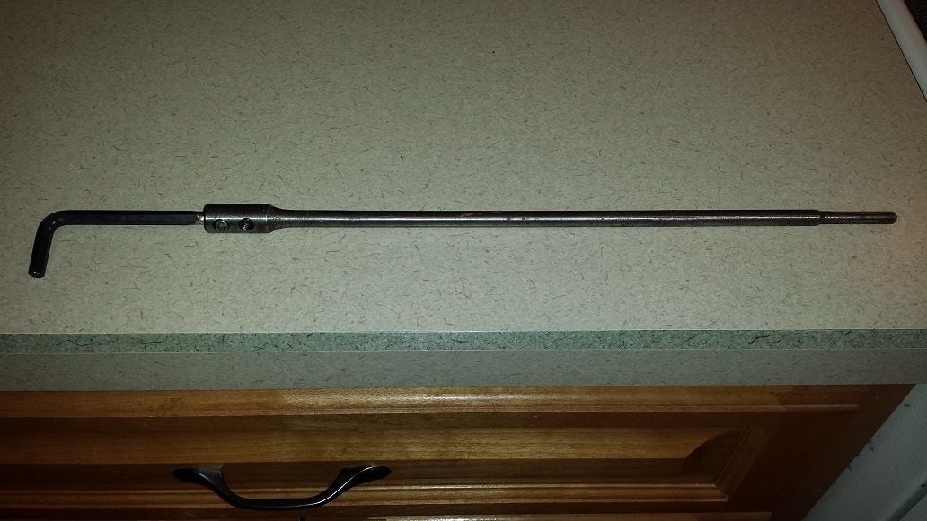
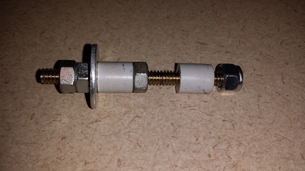
I decided that I wanted to confirm my suspicion so I made a little depth measuring tool. I put some plastic bushings on the middle of it to get it to be close to the same diameter as the sensor so as to minimize the side-to-side play and keep the measurement as accurate as possible.
Basically the tool is a bit of threaded rod with a nylon locknut on the end, then some plastic bushings with a nut between, then a washer followed by a couple of jam nuts.
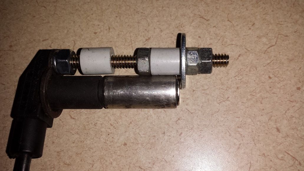
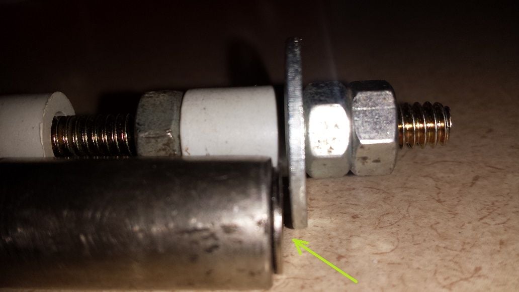
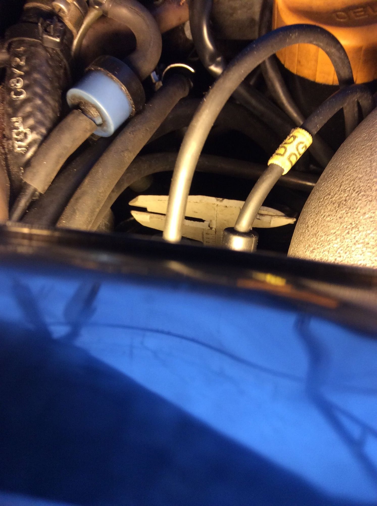
What I did was loosened the jam nuts so to a greater distance than the sensor would go in and then inserted the tool down into the speed sensor hole. then I pushed down on the threaded rod to keep it in contact with the ring gear. As I was pushing down on the threaded rod, I spun one of the jam nuts down until it was pinching the washer to the sensor bracket - then I spun the other jam nut down so that it would keep the first jam nut in place as I pulled the tool out. Once it was out I tightened the two jam nuts even further and then spun the nut between the bushings towards the washer until the upper bushing was holding the washer tightly up against the jam nuts. This allows me to compare that distance (between the end of the locknut and the bottom of the washer) to the distance of the speed sensor with the figure 8 shim and the .8mm washer glued to the bottom of it. You can see in the pictures that there is still a gap of about .5-.6 mm between the bottom of the washer and the end of the sensor with the .8 mm washer glued to the bottom of it.
That tells me that the gap is too great on the sensor bracket. Instead of a .8 mm gap, there is about a 1.3-1.4 mm gap. Which could be enough to cause the sensors to not give a good signal output and possibly cause the DME not to register the readings - resulting in poor idle and stalling.
This is all theoriy at this point - only to be proven if I can get those stubborn bolts loose on the sensor bracket and get it adjusted properly.
One question for everyone here - when setting the gap with the speed sensor and a washer glued to the bottom. Once the bracket bolts are loose, you should have the figure 8 shim installed on the sensor, correct?
To check your flywheel sensor stud, rotate the engine till you centre one in the closer hole and put one of those sliding measuring tools in
But, I doubt there�s a problem there. Focus on removing the bolts. Yes, the figure 8 is on while setting gap. The gap can be quite a bit off before problems start. If you can get access to an oscilloscope, that would be best to �see� the signal.
...and only the lower driver’s side bolt from the bottom. Might need two universals in that chain. Top passenger bolt just needs a stiff setup with ratchet. I had to use the bit holder + bit as the sides of the 3/8” hex socket are too big to fit between the bolt and side of bracket.
For that reason, I am surprised some have gotten regualr bolts to work. How does the socket fit between the head and bracket side?!? Guess I’d have to put one in to see


 05-25-2018, 08:50 PM