When you click on links to various merchants on this site and make a purchase, this can result in this site earning a commission. Affiliate programs and affiliations include, but are not limited to, the eBay Partner Network.
Well, it's running. And the culprit was...wait for it...the DME. That's right, the DME that ECU Doctors said was OK actually isn't. Yesterday, I purchased a used DME off of Craigslist for $125. The seller tested prior to my purchase, so I knew it was good. Shout out to Elliot at Elliot Porsche Parts of Blairsville, GA. Popped it in and she fired right up. In all fairness, I had sent my test results to ECU Doctors and they agreed that the DME appeared to be defective. They have already shipped out a new DME and I will ship the defective one back. Still, I am a little perturbed that they sent me down this rabbit hole by declaring the DME good back in May. They are refunding my $20 in shipping from before, too, but that and an I'm sorry are all I have to show for it.
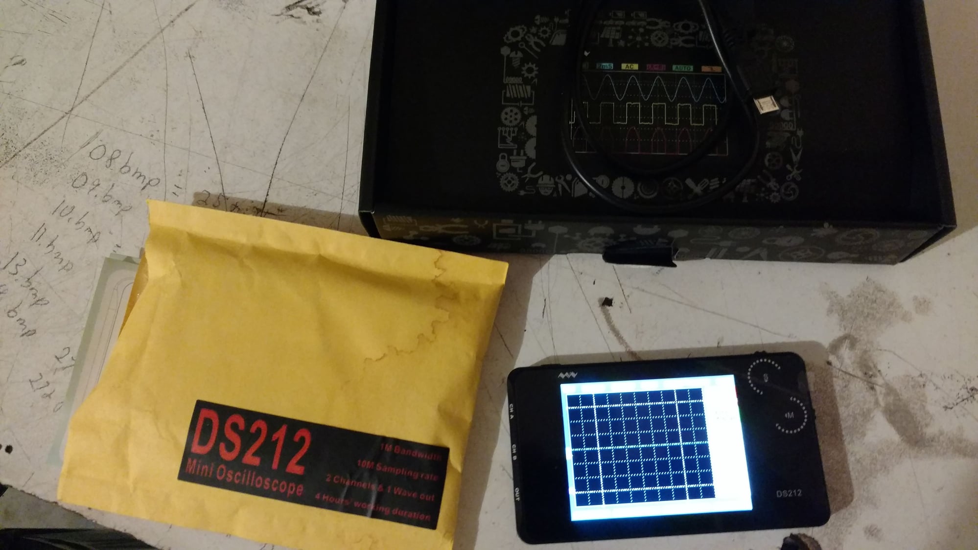
At any rate, for any future enthusiasts that stumble across this thread, I thought I would share a little more about testing the signals to isolate the DME. First off, I am not an expert at operating an oscilloscope by any means, but, I did manage to pull it off, so maybe this can help someone here in the future. For starters, here is the oscilloscope I purchased:
It was $109 shipped from Amazon. Again, just as a reminder, here is how I was able to grab signals with the DME still plugged in:
Finally, here are the settings: Channel (A or B)
Volts: Depends on the signal you are expecting, but generally 1-2 volts per division for the reference and speed sensors. When you are expecting a battery (12 volt) level signal like terminal one, you may want to use 5 volts per division.
DC Coupling
X1 probe - The DS212 only comes with X1 probes.
Timebase: 10ms
Trigger:
SyncMode - SNGL (Single) - This allows you to grab the first signal that meets the trigger threshold and automatically stops acquisition
TrigMode - Upward Slope. This means that the trigger will react to a rising signal
Source - This can be either Channel A or B. It will measure both channels if you want, but it only triggers off of one.
Threshold - the minimum voltage that will trigger taking a measurement - I generally used 1 volt
Autofit - On
You can also save your results as a bitmap and download them to a computer for later use. Hope this helps someone in the future. Let me know if you have any questions.
Congrats on solving the problem. And thanks for adding the Oscilloscope directions; I've already forgotten what settings I used (though I do recall that a longer time interval--.5s I think--gave me nicer views on some tests, esp if you look at your terminals 8&27 wild screen readings
Great video, Tom. So it seems like a good sanity check for new sensors is to use an ohmmeter to verify no connection between the metal body of the sensor and pins 1 and 2 on the connector.
Wow, what a journey! It's great to see the huge ordeal come to a happy ending.
Originally Posted by Dan Martinic
Hold that lighter just yet: the Bosch sensors for the BMW work perfect; it's what I installed. The only difference is the cord length, and it's negligible at best.
I think you'll be fine. Hopefully
PS: be sure to post back what happens!
Several years ago, I used the BMW Bosch sensors to replace the OE on my 1991 951 and they worked perfectly. I got the Bosch part numbers from an equivalency table someone posted on hear ages ago. Indeed, the cords are a bit longer than OE, though.
I do, however, occasionally have to wiggle the wires to get the car to start. Especially when re starting after having run for a while and stopped to refuel, etc.
Thinking it was the wiring harness, I ordered the replacement from Lindsey years ago, but never got around to fitting it, so I still have to wiggle the wires occasionally to get it to start.
This has probably been covered already, but how do you test the harness itself? I'm guessing this is done at the DME side of the wiring?
Thanks and congratulations again for getting it to run after all you went through.
This has probably been covered already, but how do you test the harness itself? I'm guessing this is done at the DME side of the wiring?
.
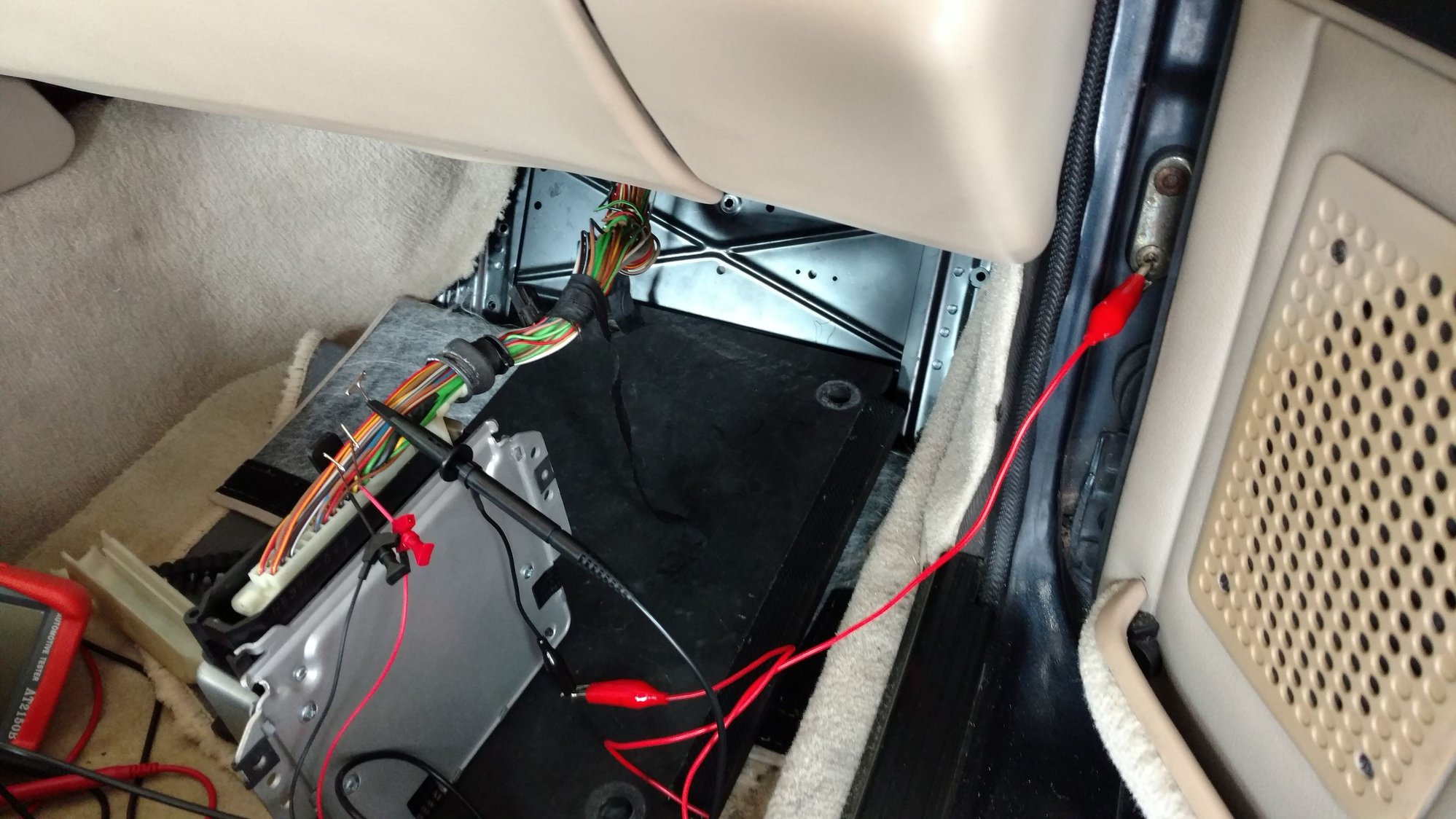
Behind the passenger footwell, when you pull the harness off the ECU (DME) you can remove its back cover. It's a screw on the end. Slide it apart (you'l have to roll back the rubber end cover too).
Then, you can insert tiny needles (or proper back-probes) into the back of the various sockets--beside the wires. Take some long extension wire and test continuity & resistance on the individual wires.
Here, you can see I've removed the harness connector's cover:
But, the problem is most likey right at the sensor connector end's boot. Pull that back and you'll probably see corroded or frayed wire
Last edited by Dan Martinic; 04-04-2019 at 09:27 AM.
I agree it's most likely frayed wires at the Junior Timer connectors that the sensors plug into. Peel back the rubber boots and check the condition of the wires. If you see any copper strands (probably black from corrosion) it means the wire insulation has broken and the signal is likely shorting out. You can also idle the motor and just wiggle the back of those connectors to see if the motor reacts or dies. If so, it's virtually certain you have bad wires on one side of the other. By the way, the exact same thing can happen with the fuel injector wires, with similar no-start results, so next time it doesn't start, look to see if you have tach bounce/twitch when you crank the motor. If no bounce/twitch, think speed and ref sensors; if you have bounce/twitch, think elsewhere like injector wires...


 07-17-2018, 10:58 PM