When you click on links to various merchants on this site and make a purchase, this can result in this site earning a commission. Affiliate programs and affiliations include, but are not limited to, the eBay Partner Network.
Thanks. I have a bare LED rated for 12V; it's just a little LED in a tiny plastic holder with two wires sticking out. Maybe there's a resistor in it.. or maybe the actual LED is just rated for 12V. Not sure. Got it from electronics surplus.
I did solder on some round connectors to those wires--the same that fit into that diagnostic plug behind the driver's side shock tower. I tried to use it when setting idle to confirm ICV is out of the picture; but, I couldn't get it to light at the appropriate time. It lights fine across 12V & ground though.
I will do some reading on the whole LED thing for sure. Seems there is a lot of uses for diagnostic around our ignition systems
If you already used it directly across +/- 12v, and it lived, then it must have the resistor already.
Just wire it to the coil terminals. BLACK is +12V and green will be the Ground from the DME. Basically, the coil gets constant 12V on black wire. The DME grounds the coil on Green to charge it. When DME releases the ground, the coil discharges to fire the plugs.
On the LED you'll see it ON/OFF flicker. You can extend the leads of the LED and tape it on your dash or windshield so you can see it while cranking.
And remember LED's only work one way, so always have the anode side (longer lead and/or flat spot) on the positive side -- i.e., the black coil wire in John's test...
Just a FYI. I am running my 1989 turbo-s DME and klr in my 86 turbo. I do this so I don't switch chips for the maf. I would recommend checking the gap on your Allen screws on the flywheel to the reference sensors. Although the ground strap is there for a reason on the bell housing you did not crank the car. The ground to the chassis is in the battery box. Stick to the basics as I read the post I feel you are over thinking. In other words the car ran before you switched sensors. . Look at the things that got disturbed, wires connectors ect. Good luck! - Glen
Ground is in the battery box? What battery box? You mean the tray that the battery sits on? Sorry; I'm confused. I know I disconnected the smaller single ground wire from the bellhousing--not sure about the other two bigger ones that are on the same screw--and turned the ignition switch to ON. I did not turn to START; just ON.
At the time, I started with the smaller ground, then thought "oh, it will be hard to get at the other stuff under the heater valve, so I better just take that out and replace it."
I did this long enough to go into the car and move the temp **** all the way to the hottest setting. Then I waited about 5 seconds... and turned the key to OFF, disconnecting the battery again, and began draining coolant.
Is the smaller ground wire on the bellhousing the main ground for the DME? The one the Porsche manual warns about being disconnected?
My point is that you didnt crank the car and therefore didn't Draw a huge slug of current. There is a ground stud where the battery is, Right next to it, Box/ Tray, call it what you will, and 12 inches below that stud is where your computers are. Just by the sheer fact you replaced the sensors and were digging around in there I would look at the Wires From the computer to the sensor.. They are not a normal wire, and they get VERY brittle from 30 years of heat, Also the Gap has to be perfect on the sensors and BTW you only need one.. . I had to replace mine, as well as the injector harness, I had a no-start and started to unplug injector thinking that one may be shorted, well, one of the WIRES was.. as soon as I unplugged it the car ran on 3 cyls..... If it was driving season I head up there in my 44 the QEW is great for a porsche...
Hopefully, I can borrow the DME offered up by DarrenD and start solving this mystery; would be a great first step to see if another DME fires it up!
I do notice one of the grey sensor wires on the harness end has cracked insulation. But, I do seem to be getting the proper sensor multimeter results.
Driving Season? Yikes! I've been driving this car for 10 years almost daily--all year long. I even switch out winter tires / wheels! I do spray a lot of corrosion-resistant stuff yearly; I invested in a small gun a long time ago. I'm in awe at the condition of the body and exhaust... only the exhaust fasteners up around the wastegate / crossover area were pretty bad; everything else strangely holds up well and all pipes are original (just switched out the CAT but the original pipes still good)
This parked-since-December situation has seen me driving my wife's Kia to work... and I'm in serious withdrawal.. especially the last two weeks with this nice sun. In fact, my favourite driving weather is slightly cool, dry, and sunny.
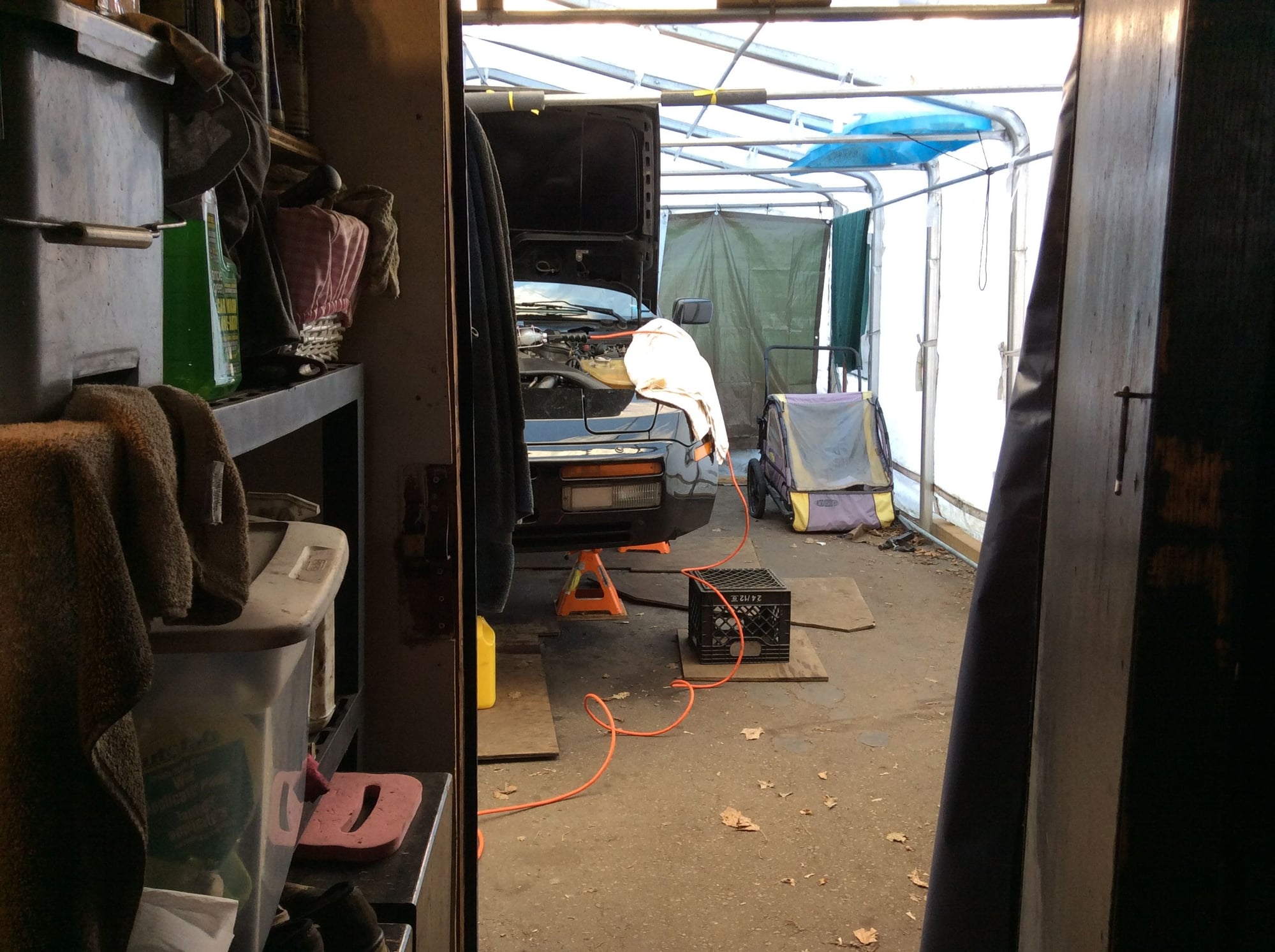
BTW that's one sweet garage & collection you got there
I do notice one of the grey sensor wires on the harness end has cracked insulation. But, I do seem to be getting the proper sensor multimeter results.
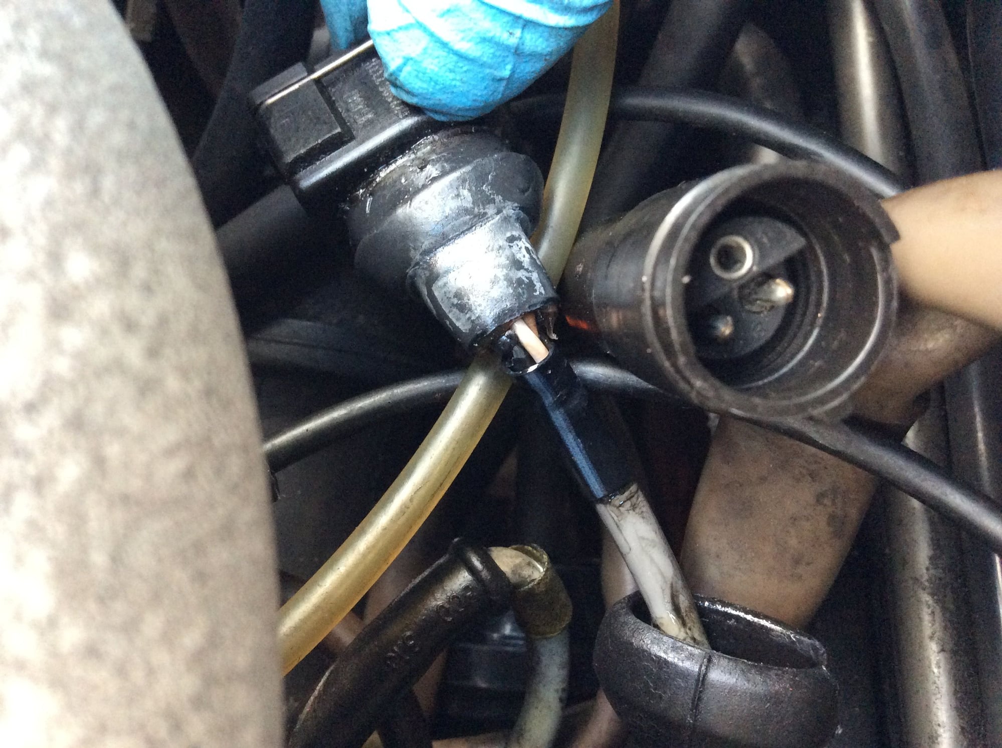
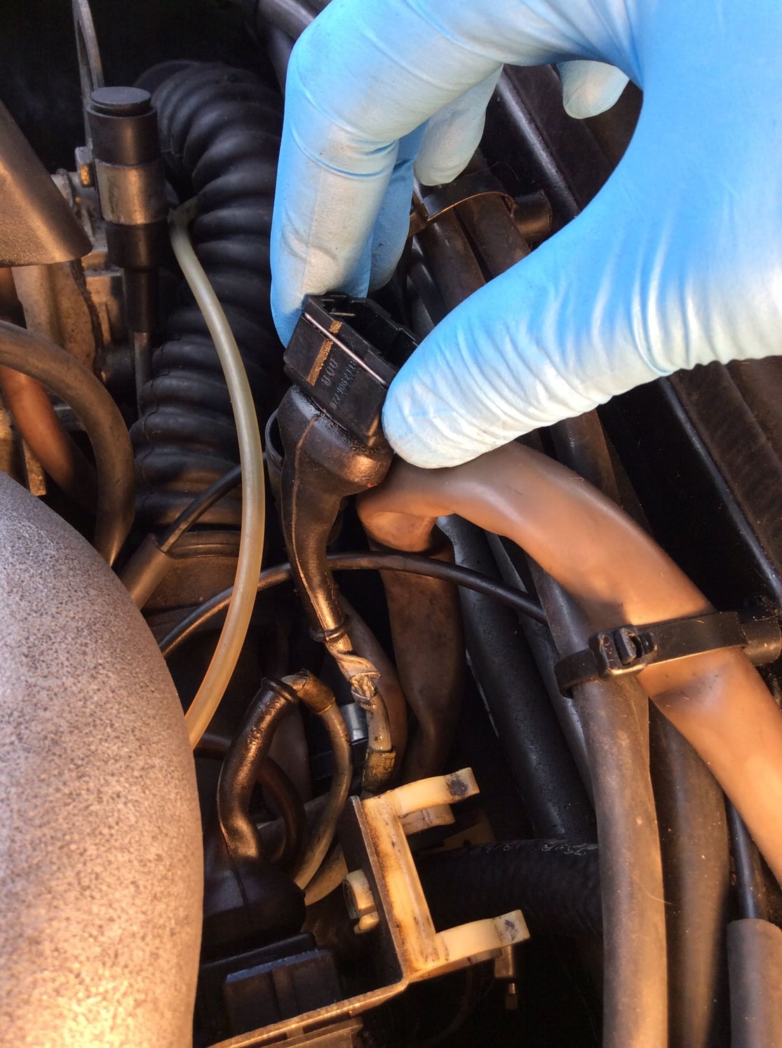
That's most likely your issue. The wires fray under the rubber boot due to the way the factory tried to "pot" the wires with an epoxy-type material. See picture below and find replacement harnesses at 944online and Lindsey. You say you have proper sensor results on the multimeter, but (a) multimeters are not a reliable way to test the signals, (b) you have no tack bounce, (c) the video you posted showed 2/10ths of a volt, not 2 volts. By fishing around in that area, the highly vulnerable/brittle wires finally failed under the boots and now it won't start. There are 3 or 4 things that cause probably 90% of the no-starts on these cars, and this is one of them. That it happened after moving those wires around makes the odds all that much higher. DO yourself a favor and peel the rubber boots back on the harness side of those connectors and take a look at the wires. I'm guessing they will look similar to this picture. If you see any copper strands, then that's almost surely why your car won't start. Too easy to check not to look...
This is what it looks like under the rubber boot. Peel your boots back and chances are good you will see copper strands.
Tom speaks a lot of sense, I�ve also had problems with damaged cables behind those connectors under the boots and also the similar connectors that plug into the fuel injectors. As those looms are both critical to the car operating reliably it�s good practise imo to swap them out if there are any visible cracks in the insulation. It�s good insurance as much as anything and they are readily available and not too expensive.
At this point I�d be tempted to wait until you�ve swapped in a known good DME, but either way I�d probably change that loom wyit if it is damaged like you say.
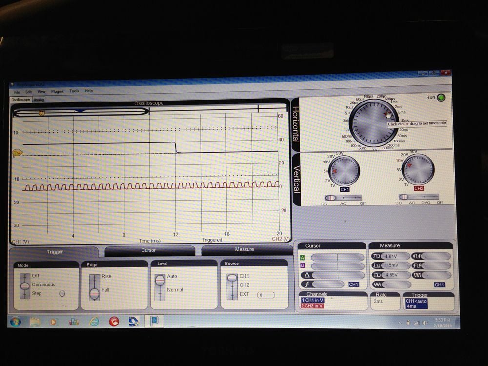
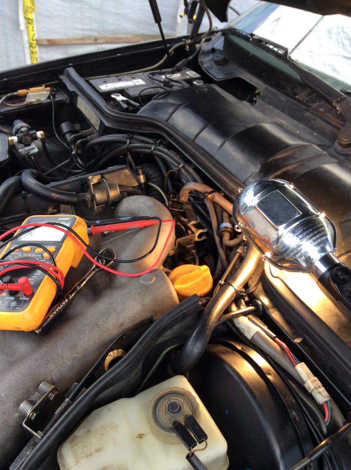
Tom is solid! Always impressed with those posts. However, gentlemen, I believe my sensors are working fine; I learned the oscilloscope this morning and just took a bunch of readings--from the DME harness. Ok.. I learned to get a signal of some sort; but I'm still confused over the time/div thing. The concept is simple but the results are.. funny.
Check them out! These all seem to indicate something is happening that should at least cause a teeny spark or tach bounce, no?
I am resolving to either get a loaner (PS DarrenD--if you're out there, check out your PMs!!) or wait to hear back about mine from "the guy".
The DG wire is more twisted than cracked and I can't see any stray copper (ok, just a quick peek--didn't remove the rubber. Oscilloscope is more fun lol!)
Well, something's happening there. The reference sensor signal looks suspect to me though. You should be getting one pulse of 2 or more volts per revolution, but if your video titles are accurate it looks like you are getting like .2 or .3 volts (and an odd pattern). Your multimeter seemed to say the same thing... Humor me, take a look under the rubber boot on the harness side of the ref connector. No guarantees, but that would be my next move for sure.
You have the probe and scope in sync on the x10 settings I trust (if you have that)?
Or, if you like playing with the scope, try (carefully) checking the signals on pins 12 and 13 of the 8051 processor on the DME while you crank. The speed and ref sensor raw signals get fed to the "S100" chip on the DME board, which converts those raw ac signals into clean 5 volt digital pulses, and those clean pulses then get sent to the hardware interrupt pins on the 8051 (i.e., pins 12 and 13). If you don't see a square(ish) 5 volt pulse on pin 12 and 13, the processor isn't getting the ref sensor or speed sensor signals, respectively. Here's a terrible picture of those signals on a pc scope...
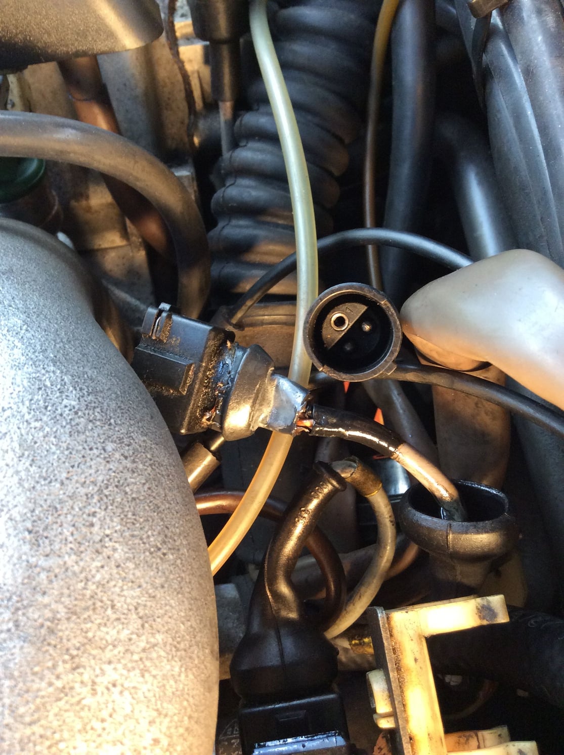
Here ya go. I see some bare wire but appears to not be the two main lines.
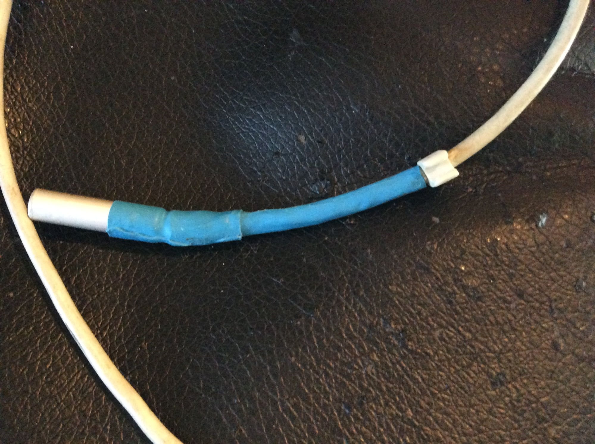
The boot was glued with something; should I glue it back? I'm thinking some heat shrink around the grey wire outside (big twisted piece missing) for now anyway. I just want to see this thing start and run!!
(I patched with cut heat shrink before.. check out the repair of computer power supply wire. Kinda hack but works?)
Oh.. I used 1x on both the probe and 'scope end.
Don't have DME at the moment; left it with 'the guy' (who may or may not know what to do with it); otherwise, I'd be all over that chip test!!
Yeah, I'd replace too, though I don't actually see the wires themselves frayed. If you re-use, I wouldn't try to glue the boot on -- that will only make life harder down the road. Try this, with the main DME connector disconnected, check for continuity between the two pins in the harness-side connectors. They should be separate with zero continuity (open, infinite resistance) so if you see any continuity between the two pins in the same connector, then there is a short inside the harness somewhere.


 03-22-2018, 11:59 AM