When you click on links to various merchants on this site and make a purchase, this can result in this site earning a commission. Affiliate programs and affiliations include, but are not limited to, the eBay Partner Network.
Oh wow thanks Laust! This is great information. That is, there's plenty of it, including some funky math formulas!
I'm going to need some translation.. but.. on first read, I get the impression that the clue to my emissions failure lies in the "dilution %".
In my search, I've found that posted emissions results seem to consistently have 14-15% as "Dilution"--just as I've had all these years (and oddly similar to stoichiometric afr)
Given that 'Dilution' is related to CO (apparently + CO2 yet turned into a percentage with the Math), and that I failed CO, seems I have not enough (or too much?) "Dilution" during the test.
I wonder if it's the fault of the testing facility? I've done most of my tests there as 1) they don't do any inspection whatsoever--the hood isn't opened and no one looks underneath--giving the impression that it's easier to pass (they also let you watch); 2) there are slow times where you pull right up, so I can drive straight off a highway run and right to the test and 3) it's mostly mechanics taking their cars there
But this time, some kid was doing it, and suspiciously, the computer screen wasn't showing any action. They just made the first tests free in Ontario; I wonder if they are failing now to get you in a second time lol
Anyway, I'm changing the O2 sensor at hefty cost but it's been on at least since I bought the car in '08 and 80K US miles.
Will be interesting to see what happens when I put it in!
Thanks for the info. I'm a little confused by the graph though. AFR? Is 1.0 on the bottom ideal AFR (then lower numbers on left = less air?)
BTW your vac manifold is super cool. I think I'll film the test tomorrow and post just to offer a view of it in testing action
The "dilution factor" is the percent of oxygen content in the exhaust, has NOTHING to do with the air-fuel ratio!!!! The technician at the emissions testing facility should be able to clarify this---if not, they have no right working there!
The dilution correction factor referenced in the CA BAR document posted by Laust is a formula to calculate the emissions results IF such a dilution of O2 is present ("X" in the equation).
So, you probably have an exhaust leak somewhere. In the state of California, a 15% dilution factor would invalidate the emissions test and the leak would need to be located and fixed (I think the limit is in the 8% range as indicated in your previous emissions test results).
But the elevated CO and HC numbers point to a degrading catalytic converter, but your already-taken first step of ordering a new O2 sensor is not a bad idea. It may not cure your issue, but if there is no change it will at least confirm that the cat likely the root issue. You might even pass the test if you get the catalytic converter really hot and bring it straight into the testing facility . . . .
Please read my posts in your other thread about the O2 sensor feedback circuit and how it works for more info . . . .
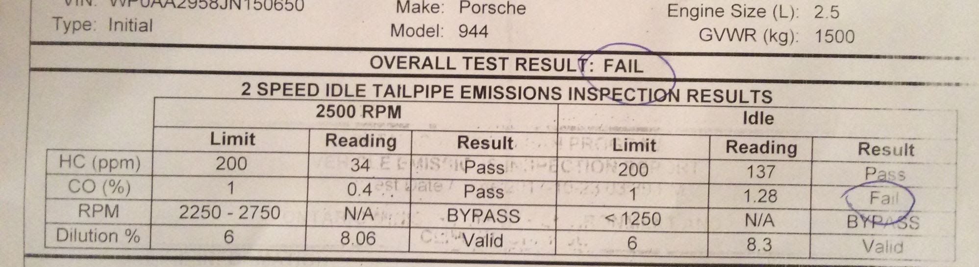
Since I've owned the car (9.5 years), I have always had pretty steady emissions results (most of the images in this thread) with 15% dilution
This latest one--the fail, and the very first image in post 1--is the only time I'm showing 8%. The limit is 6%.
I did remove the crossover and turbo for recent work, reinstalling with new seals all around. I also got a new muffler put in at a shop. The shop checked my work and said there's no leaks.
From your info, I gather that I may have had a leak before but likely don't now?
The only puzzle then is why do my other vehicles all show 14-15% dilution, as do most posts I randomly search? Seems to be the normal?
Yes, I'd also be curious as to what the criteria is for the dilution factor in ON. I'd ask the technician for an explanation, would be interesting to know.
Otherwise, I think you'll be totally OK driving the car as-is for now. Because you only barely failed the idle CO portion of the test, a fresh O2 sensor and hot catalytic converter may be all that you need to pass.
Sounds good. After I install the new sensor, I'll go in for another test and ask the operator to explain the dilution.
I can tell you that up here, they are diluting our bank accounts with this nonsense lol
I'm a little confused by the graph though. AFR? Is 1.0 on the bottom ideal AFR (then lower numbers on left = less air?)
----
Instead of AFR I should have said "Excess air factor, lambda", which is the unit on the X-axis in the graph.
Stoichiometric occurs at lambda = 1.0. Left of that is rich and lean is to the right of that. Note also that there is a curve for the voltage out of the (narrow-band) sensor.
The shaded area is the control range for the DME (when in closed loop mode). Even though the voltage dithers quite a bit, the mixture stays very close to stoichiometric.
A reason for running stoichiometric (not mentioned by Chris) is that this is the only region where a 3-way catalytic converter is simultaneously effective on all 3 pollutants (HC, CO and NOx).
From the graph, then, I read that the catalytic has the least effect on CO compared to HC and NOx.
To me, the graph also implies that there is a very small sweet spot of perfect afr; esp at the NOx rising point!
And it would seem that my O2sensor isn't reporting a rich enough mixture; it would have to read near the top of its range—close to 1V—to force the DME to correct back into the 'shade'
And since my propane test yesterday didn't cause a high reading (basically stayed the same), then my 02 sensor is clearly not functioning as designed.
Unless I did the test wrong. Next chance I get, I'll repeat it, prob on Saturday. Maybe pumping propane from a home-torch through a vac line connected to an empty vac manifold port isn't enough?
Instead of AFR I should have said "Excess air factor, lambda", which is the unit on the X-axis in the graph.
Stoichiometric occurs at lambda = 1.0. Left of that is rich and lean is to the right of that. Note also that there is a curve for the voltage out of the (narrow-band) sensor.
The shaded area is the control range for the DME (when in closed loop mode). Even though the voltage dithers quite a bit, the mixture stays very close to stoichiometric.
A reason for running stoichiometric (not mentioned by Chris) is that this is the only region where a 3-way catalytic converter is simultaneously effective on all 3 pollutants (HC, CO and NOx).
Laust
This is true, but for maximum efficiency of a 3-way catalytic converter, the A/F ratio needs to continuously oscillate between slightly rich and lean of 14.7:1. As shown by the graph, actual NOx emissions (dashed line) are minimized by a slightly rich-of-stoichiometric A/F ratio, but the HC and CO emissions (again, the dashed lines) are less when slightly lean of stoich. Hence the "dithering" voltage, which averages out to a 14.7:1 AFR if everything is healthy.
And thanks to Laust for posting that graph, it helps to explain a lot in a single image!
Would you see this dithering on a multimeter at idle? Because... I didn't
I found the new O2 sensor on my doorstep this morning. This is odd, since it wasn't there last night, and I didn't think they deliver on Saturdays?
What lousy weather! It's cold and rainy up here, and my "tent garage" leaks badly, leaving me to lie on wet plywood. And what a pain trying to screw in a new O2 sensor while fighting the wire, all with so little clearance that my nose rubs the oil pan
This is not the weather to video the old one being tested on the car, nor the new one. But, I did put the torch to the old one in the shed and can't seem to get it to read anything past .3v.
From a previous thread in 2016, I found this by Chris:
"And for posterity's sake, the O2 sensor that that Clark's Garage prescribes is completely useless: when the O2 sensor is unplugged to test the voltage, all you are seeing is open-circuit voltage, which tells you next to nothing. The O2 sensor needs to remain plugged in to complete the circuit to the DME, and the signal wire needs to be pierced or back-probed with the voltmeter positive lead, with the negative lead connected to a good ground."
So much for all this "testing" lol
The new O2 is in and I'll re-do the emissions test this coming week
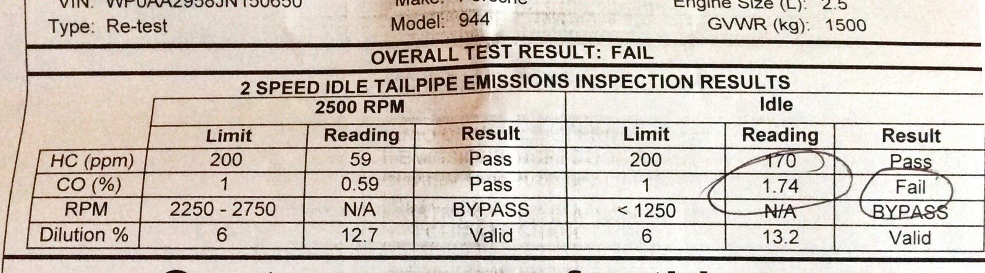
Did the re-test with a new oem O2 sensor and a 20 min highway drive.
The emissions test result is *worse*
Since the tech doesn't even open the hood, please tell me there is something I can disconnect, connect, turn, or adjust just to pass then put back to normal?
The car is otherwise running better than ever. I asked about the "Dilution" and he said that has nothing to do with my car--that it's his machine. He didn't elaborate


 10-25-2017, 10:35 PM