When you click on links to various merchants on this site and make a purchase, this can result in this site earning a commission. Affiliate programs and affiliations include, but are not limited to, the eBay Partner Network.
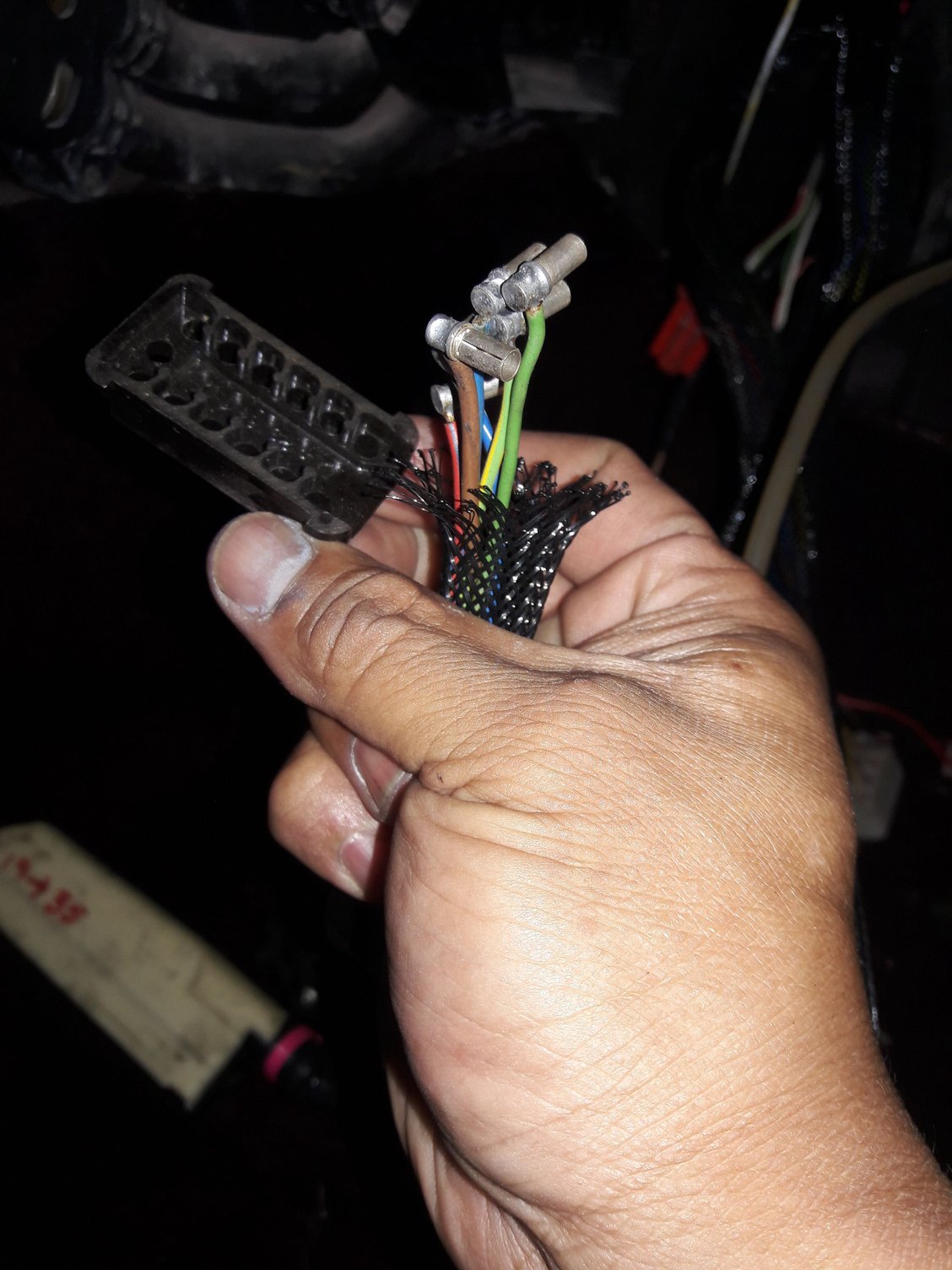
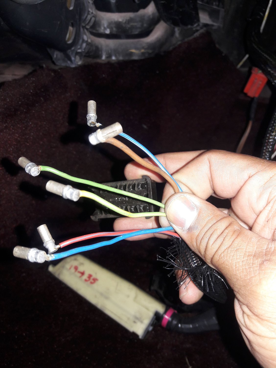
Hello everyone. I recently refurbished the harness of my project 86 944t. While taking it out, these wire which was located under the dash behind the glove box broke into pieces and the wires came out. Can anyone please help in identifying where these wires are supposed to go into the ppastic holder? And another thing, what is this for, because there wasnt anything attached to it.
If you have a Schematic (Which you now NEED) look at Vans Video on YouTube about reading Porsche Schematics. Hopefully someone will post it, Otherwise I will have to get back to this thread.. Im at work and My Schematics are home.. But If you do some do some digging on the NET You will find the pin outs faster I can share this with you.. This is the main power, I know this because I needed the main power for my standalone in the race car.. Handy to have a "Reference" car around.
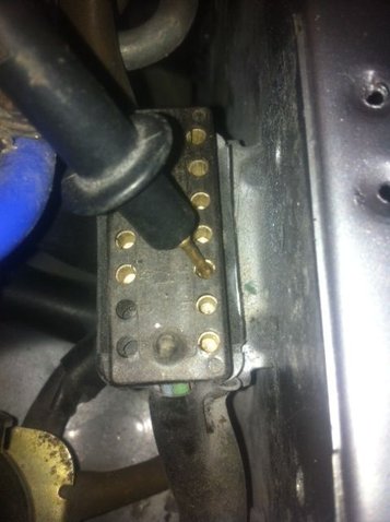
As you say, nothing plugs into this connector, so it doesn't really matter which wires go where (unless your car comes across some uber-rare and arcane factory diagnostic tool that may or may not even exist). It doesn't even show on the 86 schematic, even though 86 cars have them, so from the 87 schematic, here are the pin assignments in that connector:
pin 1: black (this is "probably an alternate for red/white wire you have, and both are "probably" a switch 12v supply)
pin 2 brown (ground)
pin 3: green/yellow (KLR pin 9, ignition input)
pin 4: blue (KLR pin 15, knock counter signal)
pin 11: green (pin 3 of KLR; blink code output)
pin 12: blue/white (pin 1 of KLR; diagnostic)
If you look closely, I believe the pin numbers are marked on that connector.

 09-01-2017, 11:11 PM