'87 Intake Removal, Repairs, Installation Procedure (w/pics)
 01-22-2009, 01:44 AM
#76
Under the Lift
Lifetime Rennlist
Member
Lifetime Rennlist
Member
And I thought I was busy enough with just one 928! Oh, I do have another in the driveway I need to get to. With 4, you must have most of the weekends booked pretty solid.
 01-22-2009, 05:34 PM
#77
Drifting
Dwayne,
Like I've said before. Its write ups like these that make me believe I can do this! Can't thank you enough. We all know you don't have to take the time to document this step by step with photos to boot....but you do and I for one appreciate it BIG TIME.
Like I've said before. Its write ups like these that make me believe I can do this! Can't thank you enough. We all know you don't have to take the time to document this step by step with photos to boot....but you do and I for one appreciate it BIG TIME.

 01-23-2009, 12:20 PM
#80
Rennlist Member
Thread Starter
Join Date: Sep 2007
Location: Ridgecrest, California
Posts: 1,363
Likes: 0
Received 143 Likes
on
28 Posts
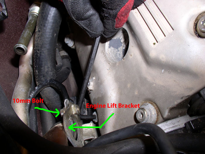
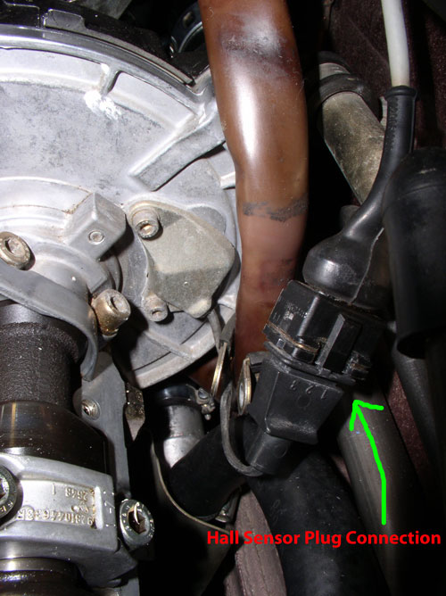
OK....one last thing to check before beginning the intake and cam cover preparation for installation - the Hall Sensor. The Hall Sensor is used by the EZK to retard the timing of a specific cylinder when combustion knock is detected. By knowing the position of the cam (through the Hall Sensor) at the time of the combustion knock (through the knock sensors), the EZK identifies the offending cylinder and retards the timing of that cylinder by 3 degrees. If knocks continue, it will retard in steps of 3 degrees to a maximum of 9 degress for that cylinder. The timing of all cylinders will be retarded 6 degrees if the knock sensors or Hall Sensor fail. The Hall Sensor is located on the passenger front side of the engine and is attached to the back side of the metal cam gear plate. You recall I did not remove the engine lift bracket when removing the cam cover because it was not necessary. However, I wanted to get a good look at the sensor and the plug connection to the wiring harness so the engine lift bracket needed to be removed. In addition, removing the lift bracket would also provide a little extra room for re-installing the cam covers which will take place shortly.
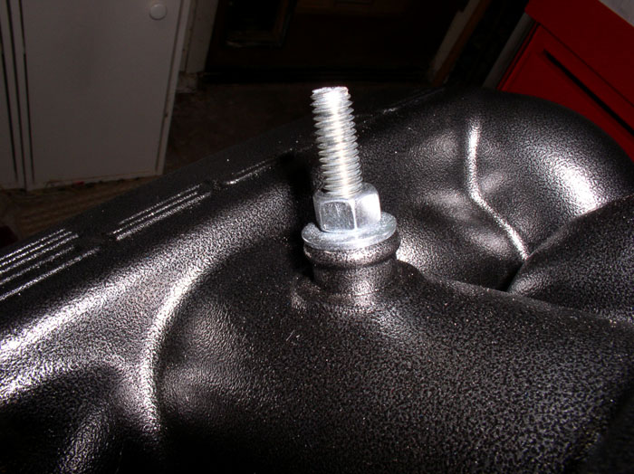
You will first need to remove the 10mm bolt that holds the wiring harness clamp to the lift bracket. There is also a ground strap wire connected to the lift bracket that runs to the passenger side coil mounting bracket. After removing the harness clamp, I reinstalled the 10mm bolt with the ground strap attached to keep them together.
Next, you'll need to remove the 13mm bolt that secures the lift bracket to the engine head. I found it easier to access this bolt from undeneath the car using a 12" + 6" extension with universal elbow. Although the lift bracket has two mounting holes, only one bolt is used to secure it. The other mounting hole slips over a mounting pin that extrudes from the side of the head.
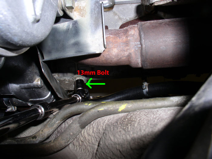
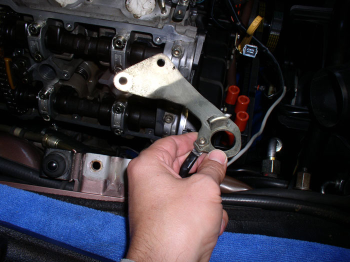
After the 13mm bolt is removed, you can take out the lift bracket and set it aside.
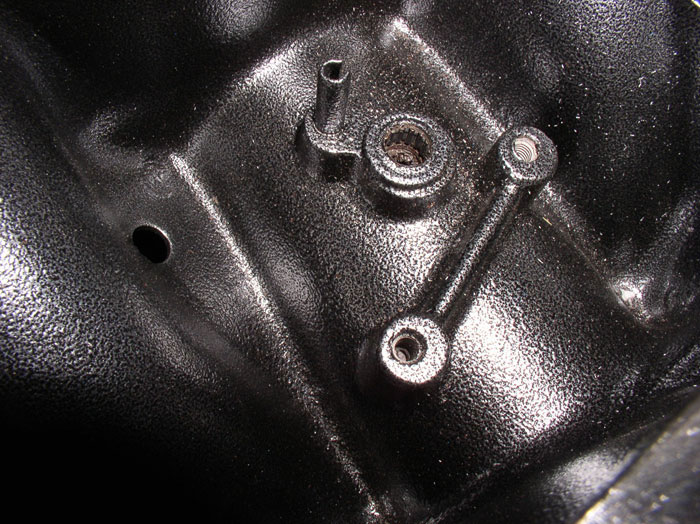
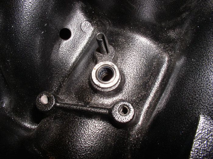
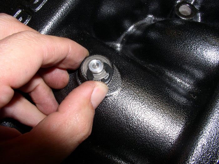
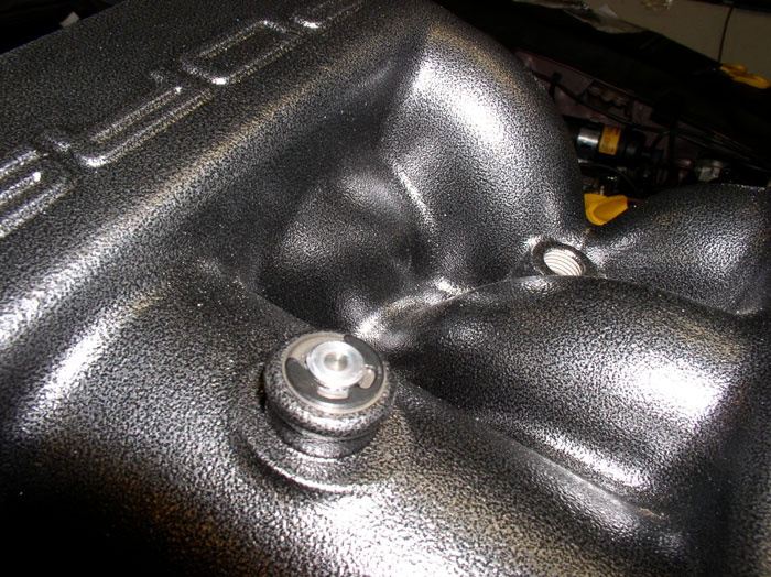
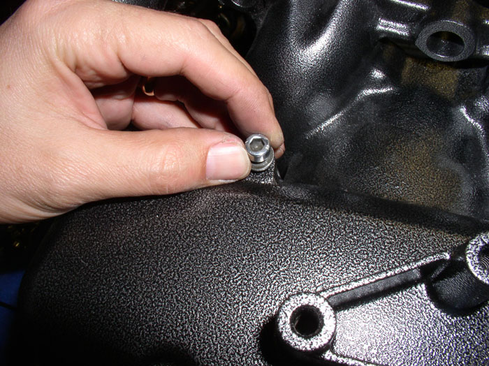
Here's a shot of the Hall Sensor. It's mounted with two 5mm allen head bolts. If your sensor is known to be bad, now's the time to replace it while it's easy to access. I don't believe mine was causing any problems so I decided not to replace it until I had evidence it was broke. If you replace yours, the tightening torque for the mounting bolts is 6 ftlbs or 72 inch pounds.
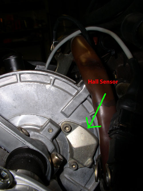
Here's the Hall Sensor plug connection to the wiring harness. This connection is typically the failure point. The sensor side of the connection becomes brittle and cracks and no longer secures a good connection with the wiring harness.
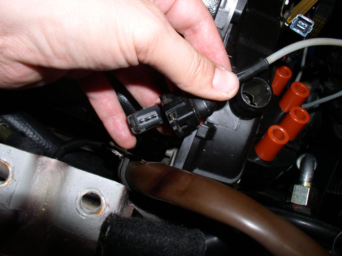
Unplug the Hall Sensor from the wiring harness and inspect the plugs condition. Mine actually looked just fine, no discolorations or cracks visible. The electrical connections themselves also looked clean and free of dirt and corrosion. If you find no problems with the Hall Sensor plug connection, re-connect the plug to the harness. Leave the lift bracket off until the cam cover is installed. If your Sensor plug is cracked or shows signs of discoloration or brittleness, I would recommend replacing the Hall Sensor - it will come with a new plug connector.
continued.....
You will first need to remove the 10mm bolt that holds the wiring harness clamp to the lift bracket. There is also a ground strap wire connected to the lift bracket that runs to the passenger side coil mounting bracket. After removing the harness clamp, I reinstalled the 10mm bolt with the ground strap attached to keep them together.
Next, you'll need to remove the 13mm bolt that secures the lift bracket to the engine head. I found it easier to access this bolt from undeneath the car using a 12" + 6" extension with universal elbow. Although the lift bracket has two mounting holes, only one bolt is used to secure it. The other mounting hole slips over a mounting pin that extrudes from the side of the head.
After the 13mm bolt is removed, you can take out the lift bracket and set it aside.
Here's a shot of the Hall Sensor. It's mounted with two 5mm allen head bolts. If your sensor is known to be bad, now's the time to replace it while it's easy to access. I don't believe mine was causing any problems so I decided not to replace it until I had evidence it was broke. If you replace yours, the tightening torque for the mounting bolts is 6 ftlbs or 72 inch pounds.
Here's the Hall Sensor plug connection to the wiring harness. This connection is typically the failure point. The sensor side of the connection becomes brittle and cracks and no longer secures a good connection with the wiring harness.
Unplug the Hall Sensor from the wiring harness and inspect the plugs condition. Mine actually looked just fine, no discolorations or cracks visible. The electrical connections themselves also looked clean and free of dirt and corrosion. If you find no problems with the Hall Sensor plug connection, re-connect the plug to the harness. Leave the lift bracket off until the cam cover is installed. If your Sensor plug is cracked or shows signs of discoloration or brittleness, I would recommend replacing the Hall Sensor - it will come with a new plug connector.
continued.....
01-23-2009, 11:34 PM
#81
Rennlist Member
Thread Starter
Join Date: Sep 2007
Location: Ridgecrest, California
Posts: 1,363
Likes: 0
Received 143 Likes
on
28 Posts
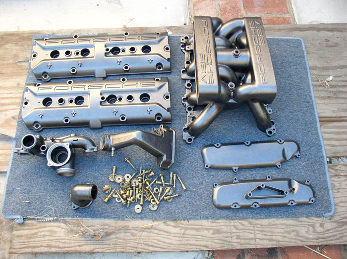
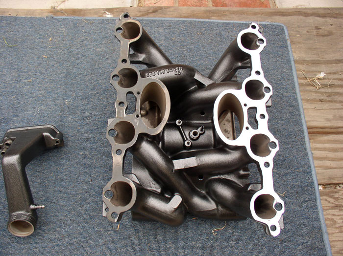
So I received my parts back from the Powder Coaters. I used Olympic Coatings in Escondido, CA. I went with a textured finish to hide the casting imperfections and a darker color to hide dirt/dust better. This finish is called silver vein. For all of these parts, it cost about $250 and took about 3.5 weeks.
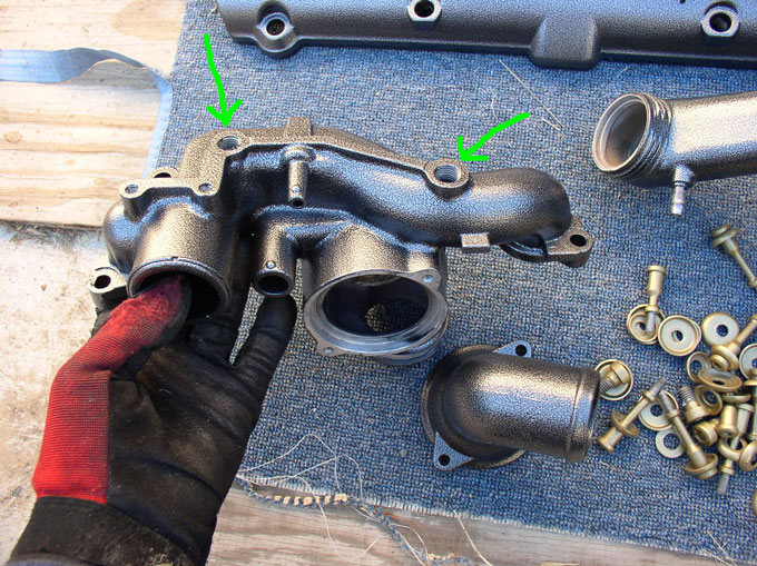
If you had parts powder coated like mine, there may be some cleanup work required before reassembly. For example, depending on how good the powder coater masked off threads and ports, you may have to sand or file powder coating residue from some of those surfaces. On my water bridge, since I went with a textured finish, I needed to file smooth the mating surface for both the Temp II sensor and the Temp guage sending unit as shown below oOtherwise, I had leaks. I used a file to maintain a level surface vs using sandpaper. No need to file all the powdercoating off, just enough to smooth out the textured finish so the sealing ring gets good contact on the water bridge surface.
The mating surface on the intake runners also had residue. I used a wire brush wheel on a bench buffer to clean these surfaces. A coarse wheel with light pressure worked well for me (being careful not to introduce heavy scratches in the intake mating surface.
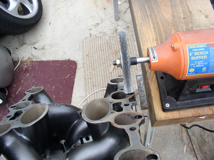
Here's the difference after cleaning one side.
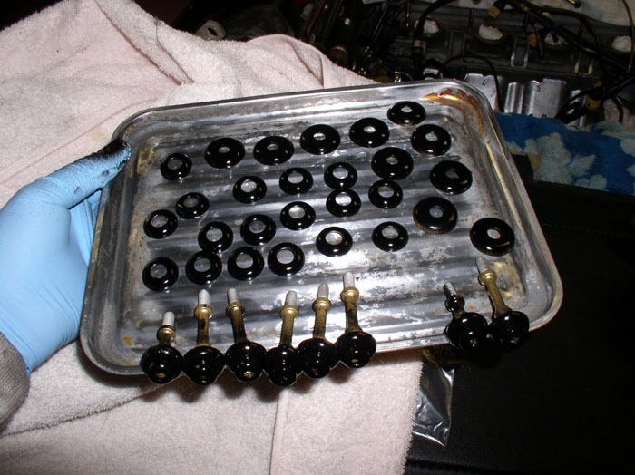
I had the cam cover bolts and intake umbrella washers also powder coated a brass finish - hoping it would look similar to the orginial finish but was disappointed in the color. Therefore, I repainted the visible areas of this hardware with engine enamel, gloss black and liked it much better.
If you sent your intake to the powder coaters, it's likely you will need to replace your flappy bearings. Although, I understand some have been able to simply clean the bearings in place and re-use them. If you have a vacuum leak at the flappy bearings, you will need to replace the seals or the bearings themselves that come with new seals, if you want to cure the leak. Roger sells the correct replacement bearings and they come with double seals.
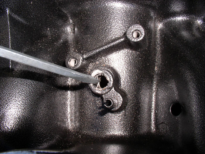
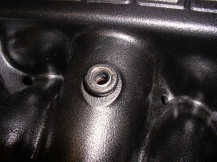
To replace the bearings with seals, first pry up the needle bearing cage with a small flat blade screwdriver.
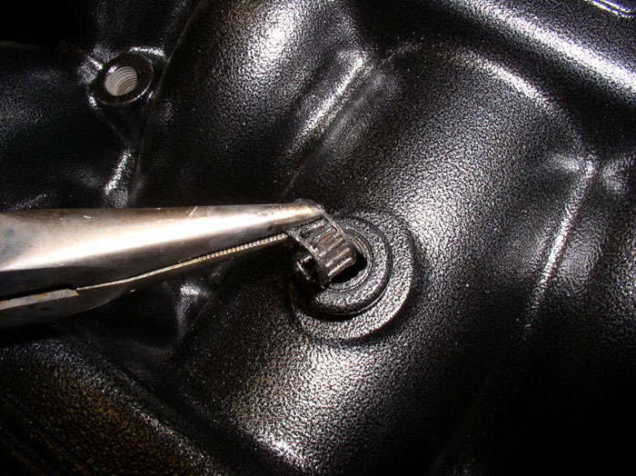
Then, use a pair of needle nose pliers to extract the needle bearing cage.
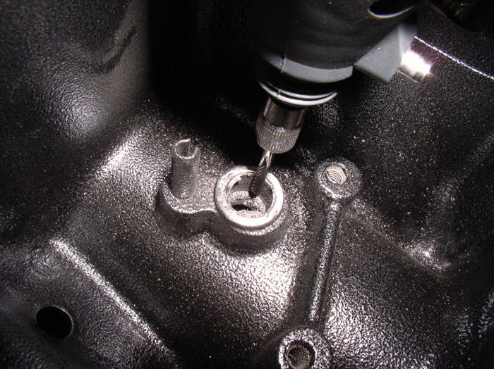
After removing all the left over needle bearings, I cut the bearing casing using a dremel Tungsten Carbide Cutter No. 9901. I learned this technique by reading one of Schocki's posts. THANKS, Schocki! Keep the cutting bit level and parallel with the bearing casing to cut a consistent penetrating groove in the casing. Apply light pressure and take your time - especially if it's your first time. I stopped frequently and checked the depth of cut. You will know when you cut through when you see the metal underneath the cutter change to a bright silver ( this is the aluminum seat - the intake). Cut lightly and make sure you have a steady line all the way down the length of the bearing casing. At that point, you should be able to pry under the lip of the bearing casing with a screwdriver to break it loose.
Once the bearing is broke loose, extract it with a pair of needle nose pliers.
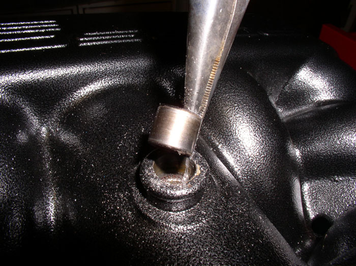
Here's a pic of the cut bearing casing.
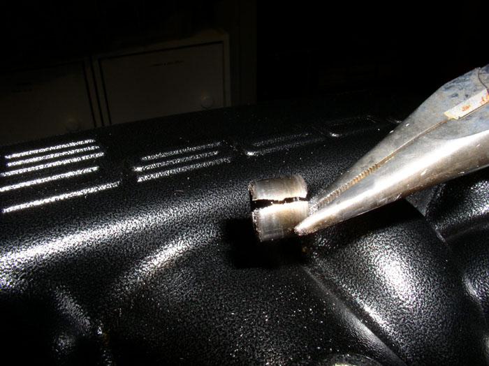
The objective is to cut through the casing with minimal scoring to the bearing seat. Perform the same operation on the bearing on the other side of the intake
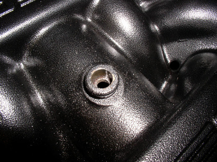
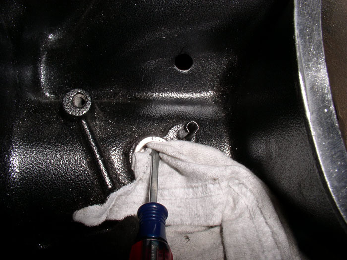
Next, clean the bearing seats with a clean rag - a flat blade screwdriver helps.
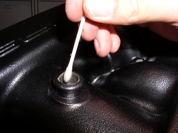
Lubricate the bearing seats with WD-40 or similar product. I used a q-tip to apply the lubricant.
To install the new bearings, I used a 12" length of 3/8" threaded rod (from Home Depot) and also bought two nuts and two washers to go with it.
continued...
If you had parts powder coated like mine, there may be some cleanup work required before reassembly. For example, depending on how good the powder coater masked off threads and ports, you may have to sand or file powder coating residue from some of those surfaces. On my water bridge, since I went with a textured finish, I needed to file smooth the mating surface for both the Temp II sensor and the Temp guage sending unit as shown below oOtherwise, I had leaks. I used a file to maintain a level surface vs using sandpaper. No need to file all the powdercoating off, just enough to smooth out the textured finish so the sealing ring gets good contact on the water bridge surface.
The mating surface on the intake runners also had residue. I used a wire brush wheel on a bench buffer to clean these surfaces. A coarse wheel with light pressure worked well for me (being careful not to introduce heavy scratches in the intake mating surface.
Here's the difference after cleaning one side.
I had the cam cover bolts and intake umbrella washers also powder coated a brass finish - hoping it would look similar to the orginial finish but was disappointed in the color. Therefore, I repainted the visible areas of this hardware with engine enamel, gloss black and liked it much better.
If you sent your intake to the powder coaters, it's likely you will need to replace your flappy bearings. Although, I understand some have been able to simply clean the bearings in place and re-use them. If you have a vacuum leak at the flappy bearings, you will need to replace the seals or the bearings themselves that come with new seals, if you want to cure the leak. Roger sells the correct replacement bearings and they come with double seals.
To replace the bearings with seals, first pry up the needle bearing cage with a small flat blade screwdriver.
Then, use a pair of needle nose pliers to extract the needle bearing cage.
After removing all the left over needle bearings, I cut the bearing casing using a dremel Tungsten Carbide Cutter No. 9901. I learned this technique by reading one of Schocki's posts. THANKS, Schocki! Keep the cutting bit level and parallel with the bearing casing to cut a consistent penetrating groove in the casing. Apply light pressure and take your time - especially if it's your first time. I stopped frequently and checked the depth of cut. You will know when you cut through when you see the metal underneath the cutter change to a bright silver ( this is the aluminum seat - the intake). Cut lightly and make sure you have a steady line all the way down the length of the bearing casing. At that point, you should be able to pry under the lip of the bearing casing with a screwdriver to break it loose.
Once the bearing is broke loose, extract it with a pair of needle nose pliers.
Here's a pic of the cut bearing casing.
The objective is to cut through the casing with minimal scoring to the bearing seat. Perform the same operation on the bearing on the other side of the intake
Next, clean the bearing seats with a clean rag - a flat blade screwdriver helps.
Lubricate the bearing seats with WD-40 or similar product. I used a q-tip to apply the lubricant.
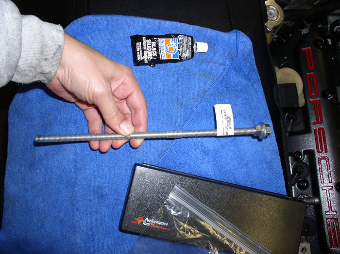
To install the new bearings, I used a 12" length of 3/8" threaded rod (from Home Depot) and also bought two nuts and two washers to go with it.
continued...
01-23-2009, 11:49 PM
#82
Rennlist Member
Thread Starter
Join Date: Sep 2007
Location: Ridgecrest, California
Posts: 1,363
Likes: 0
Received 143 Likes
on
28 Posts
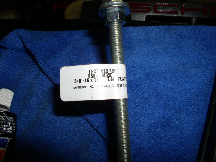
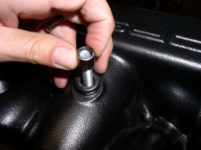
Here's a close up of the threaded rod I purchased from HD. I found the 3/8" thread to fit perfectly inside the bearings.
Put one nut and one washer on the threaded rod and insert the rod through the bearing seat (it doesn't matter if you start with the top or bottom bearing)....
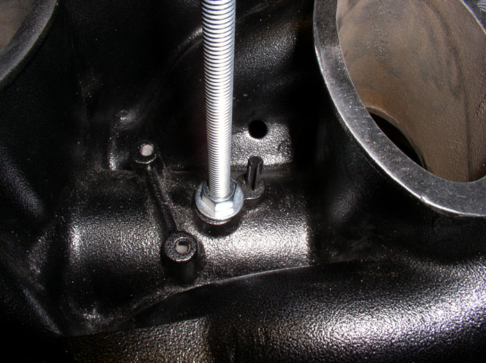
....and out the other side with enough thread to place a bearing and nut with washer.
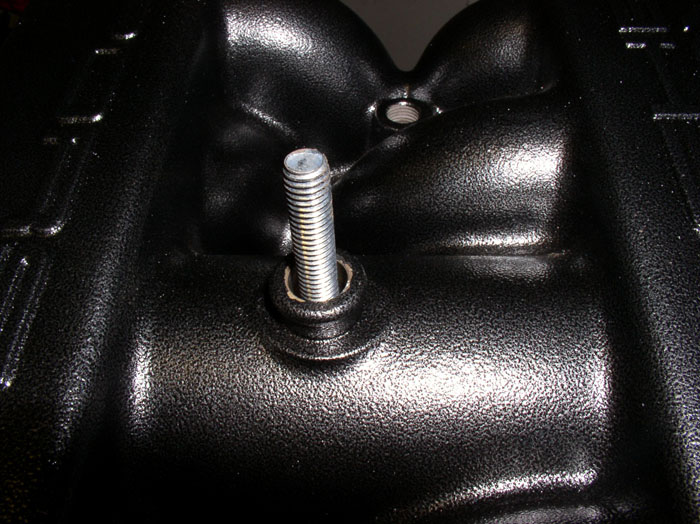
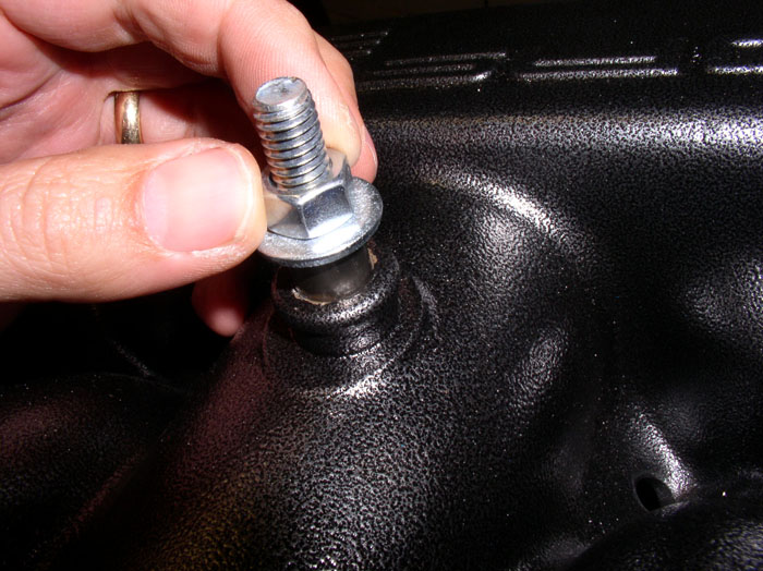
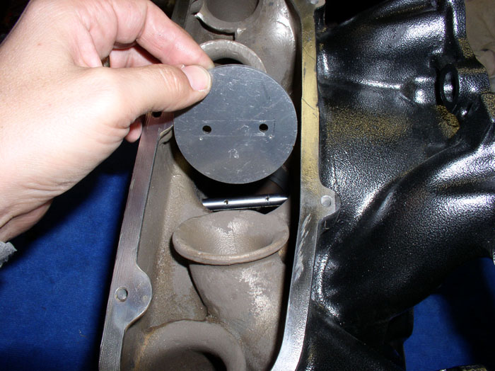
Place a bearing on the rod with the flat edge facing down toward the intake seat. The rounded edge of the bearing should be facing up away from the intake as shown. When placing the bearing on the threaded rod, be careful not to force the bearing on so as to distort or displace the small seals inside the bearing.
Place a washer and a nut on the rod and finger tighten down.
Use a 9/16" wrench to turn the nut while counterholding the other nut on the other end of the rod.
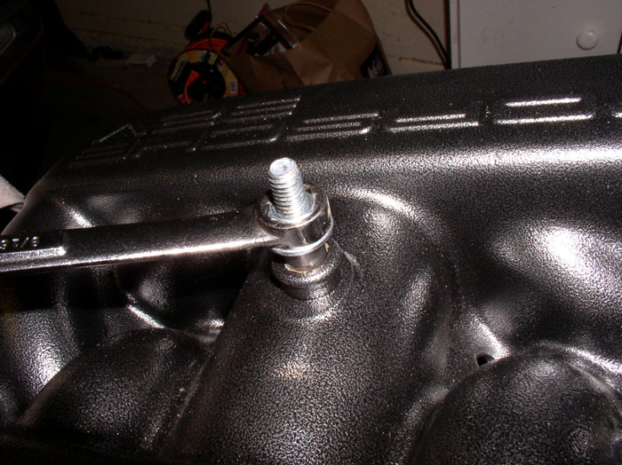
Tighten down the nut. You should not encounter much resistance at all.
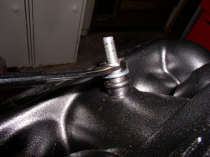
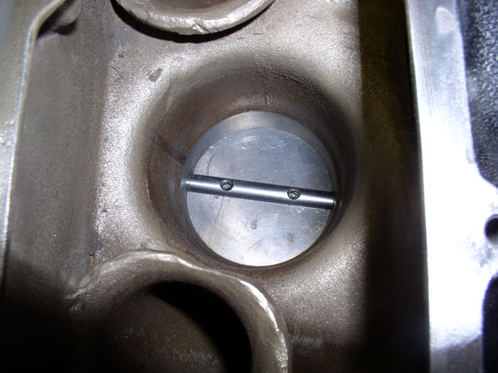
Tighten down until the washer is flush with the intake.
Then remove the nut and washer. Carefully extract the rod being carefull not to displace the bearing seals.
Perform the same operation on the other bearing on the opposite end of the intake.
Congratulations.....you just completed the flappy bearing replacement!
continued....
Put one nut and one washer on the threaded rod and insert the rod through the bearing seat (it doesn't matter if you start with the top or bottom bearing)....
....and out the other side with enough thread to place a bearing and nut with washer.
Place a bearing on the rod with the flat edge facing down toward the intake seat. The rounded edge of the bearing should be facing up away from the intake as shown. When placing the bearing on the threaded rod, be careful not to force the bearing on so as to distort or displace the small seals inside the bearing.
Place a washer and a nut on the rod and finger tighten down.
Use a 9/16" wrench to turn the nut while counterholding the other nut on the other end of the rod.
Tighten down the nut. You should not encounter much resistance at all.
Tighten down until the washer is flush with the intake.
Then remove the nut and washer. Carefully extract the rod being carefull not to displace the bearing seals.
Perform the same operation on the other bearing on the opposite end of the intake.
Congratulations.....you just completed the flappy bearing replacement!
continued....
01-23-2009, 11:59 PM
#83
Basic Sponsor
Rennlist
Site Sponsor
Rennlist
Site Sponsor
Dwayne,
The Master - thank you.
Roger
The Master - thank you.
Roger
__________________

Does it have the "Do It Yourself" manual transmission, or the superior "Fully Equipped by Porsche" Automatic Transmission? George Layton March 2014
928 Owners are ".....a secret sect of quietly assured Porsche pragmatists who in near anonymity appreciate the prodigious, easy going prowess of the 928."
Does it have the "Do It Yourself" manual transmission, or the superior "Fully Equipped by Porsche" Automatic Transmission?
George Layton March 2014928 Owners are ".....a secret sect of quietly assured Porsche pragmatists who in near anonymity appreciate the prodigious, easy going prowess of the 928."
01-24-2009, 12:59 AM
#85
Rennlist Member
Thread Starter
Join Date: Sep 2007
Location: Ridgecrest, California
Posts: 1,363
Likes: 0
Received 143 Likes
on
28 Posts
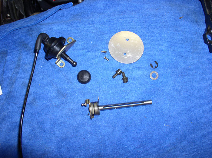
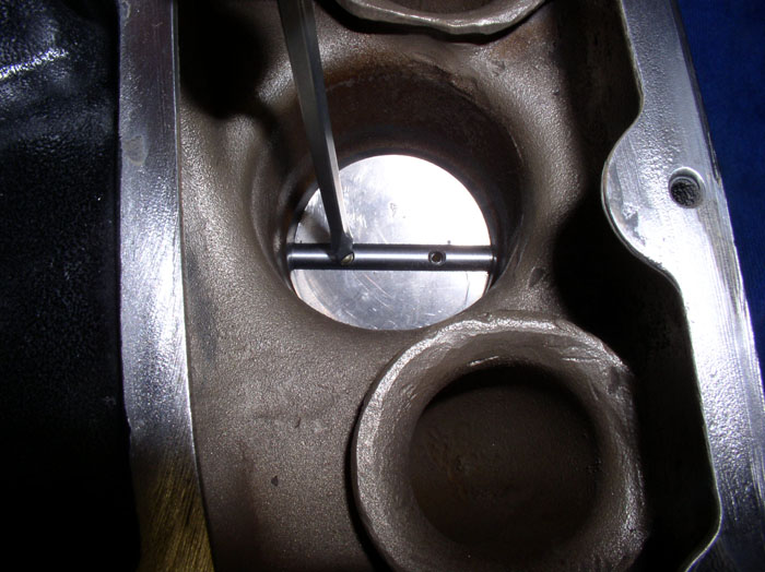
After the bearings are installed, you can install the flappy valve (plate and shaft) and vacuum diaphram next. The flappy shaft has plastic washers, a spring, spring washer and flat washers. Here's the oder these parts were on my flappy.
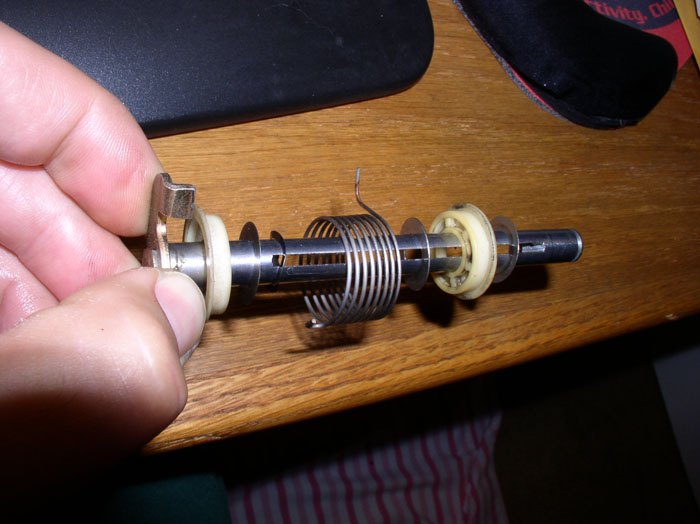
Here's all the parts that need to be re-installed that are part of the flappy system.
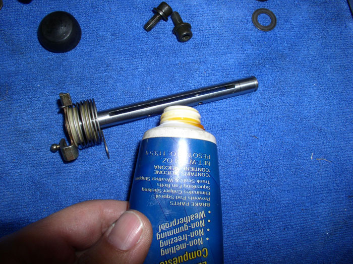
Start by applying a light coat of silicone lubricant on the flappy plate shaft before installation.
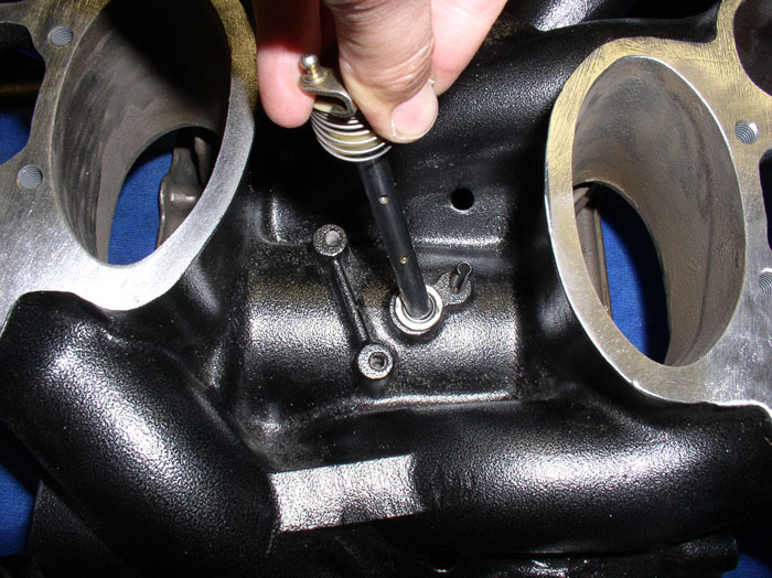
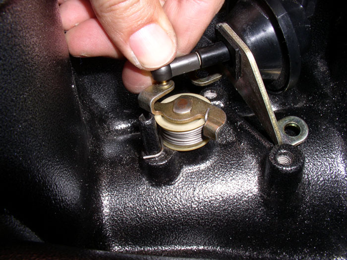
Insert the flappy shaft with hardware in the correct order (as shown above) through the bottom bearing. Be careful while inserting the shaft to ensure the seals in the bearing do not distort. I used a twisting motion on the install. When you insert the shaft all the way to the bottom of the bearing seat, you can position the spring onto the spring catch (the spindle protruding up from the bottom of the intake just to the right of the flappy plate shaft - see pic). IIRC, to get the proper tension on the spring and plate action, I wound the spring about twice around the shaft in a tightening direction.
On the topside of the intake, install the retaining washer....
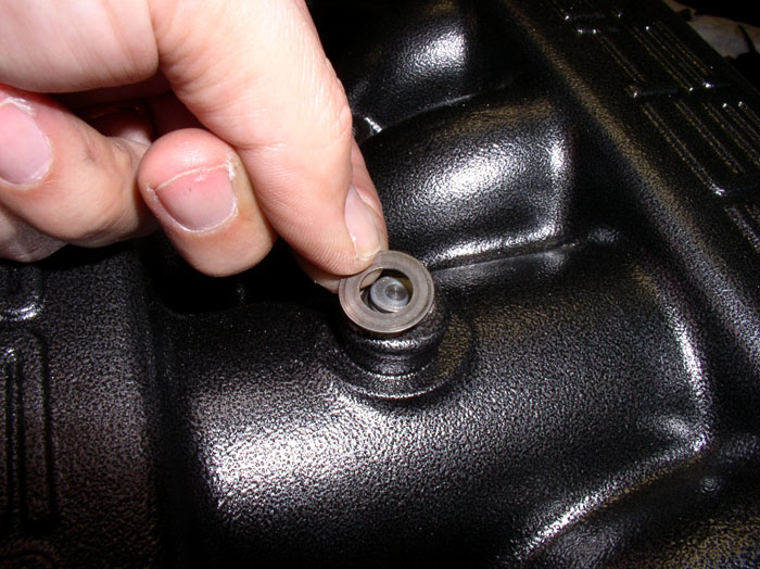
...followed by the spring circlip.
Ensure the circlip is fully seated in the groove in the flappy shaft.
Next, rotate the flappy shaft 90 degrees and insert the flappy plate into the slot in the shaft. Orient the plate in the same manner as before the disassembly. If you marked the plate, follow the indications on your markings. If you didn't mark the orientation, you'll need to examine the camfers on the plate and make sure they are positioned to mate smoothly against the wall of the intake.
After you've inserted the plate, operate the shaft/plate without the screws inserted to ensure smooth operation of the valve. There should be no sticking or rubbing. After fine adjustments to ensure smooth operation....
....install the mounting screws. I used threadlocker blue on the threads of the screws before installation. Tighten down the screws. Re-check operation of the plate and ensure smooth operation.
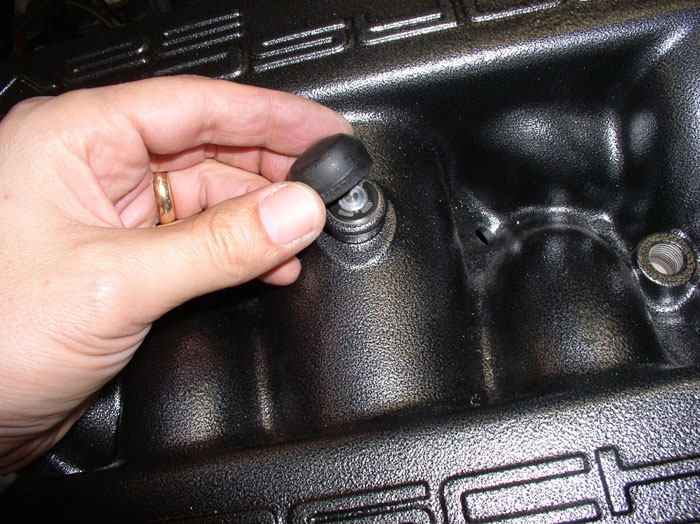
Install the rubber cap on top of the intake.
Position the diaphram unit over the mounting holes as shown and line up the diaphram ball connector with the ball on the flappy shaft lever arm.
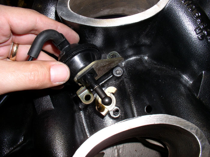
Note how the spring catches are attached. One on the intake spindle and the other end of the spring on the shaft lever arm. Press the diaphram ball connector onto the ball of the lever arm as shown.
Install the mounting bolts. Two 5mm allen head bolts. I used about 6-7 fllbs torque or about 75 inch lbs.
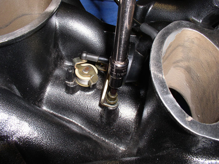
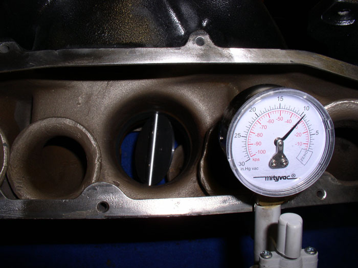
Finally, connect a hand vacuum pump up to the diaphram vacuum elbow and test operation of the diaphram and flappy valve under vacuum. It should operate smoothly. Mine would begin to move at about 5 inHG vacuum and would be fully open about 12-13 inHG vacuum. This was about the same as before the disassembly.
Flappy Valve and Diaphram Installation complete!
continued.....
Here's all the parts that need to be re-installed that are part of the flappy system.
Start by applying a light coat of silicone lubricant on the flappy plate shaft before installation.
Insert the flappy shaft with hardware in the correct order (as shown above) through the bottom bearing. Be careful while inserting the shaft to ensure the seals in the bearing do not distort. I used a twisting motion on the install. When you insert the shaft all the way to the bottom of the bearing seat, you can position the spring onto the spring catch (the spindle protruding up from the bottom of the intake just to the right of the flappy plate shaft - see pic). IIRC, to get the proper tension on the spring and plate action, I wound the spring about twice around the shaft in a tightening direction.
On the topside of the intake, install the retaining washer....
...followed by the spring circlip.
Ensure the circlip is fully seated in the groove in the flappy shaft.
Next, rotate the flappy shaft 90 degrees and insert the flappy plate into the slot in the shaft. Orient the plate in the same manner as before the disassembly. If you marked the plate, follow the indications on your markings. If you didn't mark the orientation, you'll need to examine the camfers on the plate and make sure they are positioned to mate smoothly against the wall of the intake.
After you've inserted the plate, operate the shaft/plate without the screws inserted to ensure smooth operation of the valve. There should be no sticking or rubbing. After fine adjustments to ensure smooth operation....
....install the mounting screws. I used threadlocker blue on the threads of the screws before installation. Tighten down the screws. Re-check operation of the plate and ensure smooth operation.
Install the rubber cap on top of the intake.
Position the diaphram unit over the mounting holes as shown and line up the diaphram ball connector with the ball on the flappy shaft lever arm.
Note how the spring catches are attached. One on the intake spindle and the other end of the spring on the shaft lever arm. Press the diaphram ball connector onto the ball of the lever arm as shown.
Install the mounting bolts. Two 5mm allen head bolts. I used about 6-7 fllbs torque or about 75 inch lbs.
Finally, connect a hand vacuum pump up to the diaphram vacuum elbow and test operation of the diaphram and flappy valve under vacuum. It should operate smoothly. Mine would begin to move at about 5 inHG vacuum and would be fully open about 12-13 inHG vacuum. This was about the same as before the disassembly.
Flappy Valve and Diaphram Installation complete!
continued.....
01-24-2009, 02:03 AM
#86
Rennlist Member
Thread Starter
Join Date: Sep 2007
Location: Ridgecrest, California
Posts: 1,363
Likes: 0
Received 143 Likes
on
28 Posts
Next, install the intake side covers with gaskets. Each side cover is different so the gaskets are fitted for their respective cover.
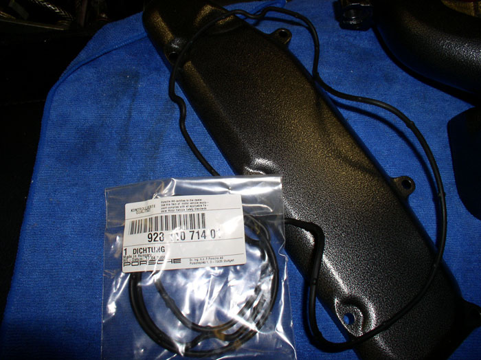
As you lay in the gasket into the side cover channel, notice the rubber tabs on the gasket - designed to hold the gasket in place. Therefore, no adheasive/sealant is required on these gaskets.
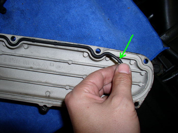
Next, position the cover with gasket installed onto the intake and install the 5mm allen head bolts. Torque the bolts to 8 ftlbs or 96 inch lbs.
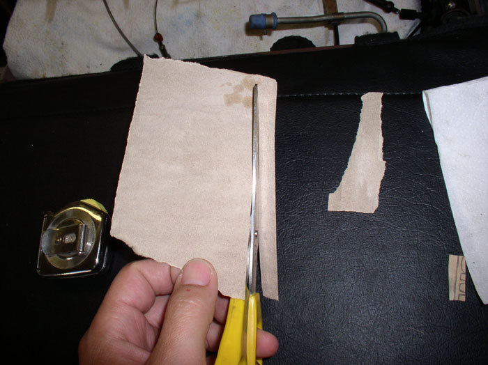
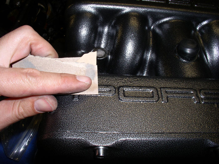
If you decide to paint the lettering on the intake and cam covers and you will be painting over the powder coat surface, you will need to prepare the cam cover and intake surfaces for the paint. I used 150 grit sandpaper. Cut a strip approximately 1/4" wide and about 6" long.
Fold the sandpaper in half lengthwise so it's about 1/8" wide.
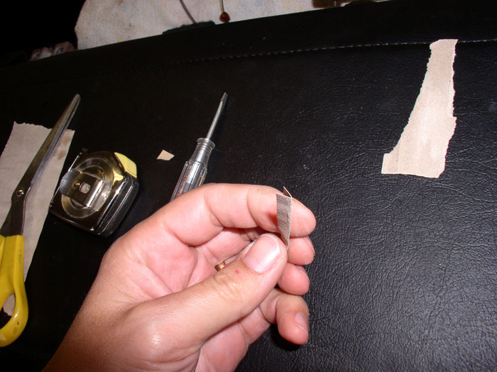
Select a small, narrow blade screwdriver ensuring the blade fits between the recessed lettering grooves.
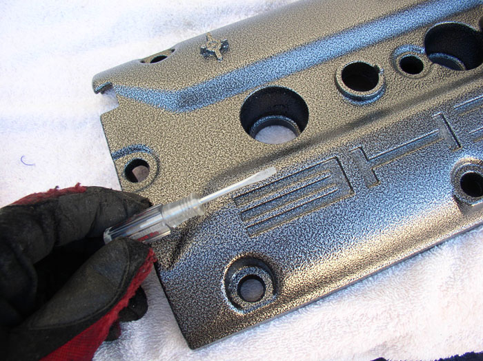
Bend the sandpaper strip over the tip of the screwdriver as pictured and lightly sand the "flat" of the letters on the cam covers. No need to try to remove the existing powder coat or painted surface. The objective is to simply roughen up the surface so the paint will bond better.
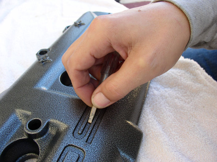
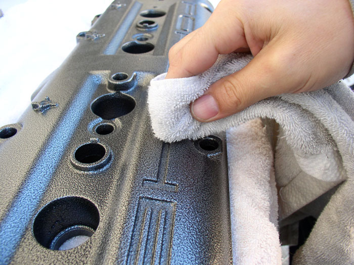
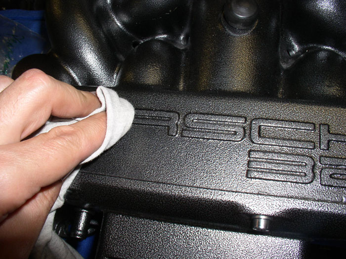
After the light sanding, use a damp (not wet) terry cloth rag to wipe the freshly sanded letters clean of dust.
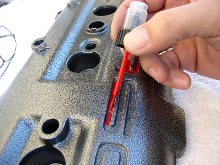
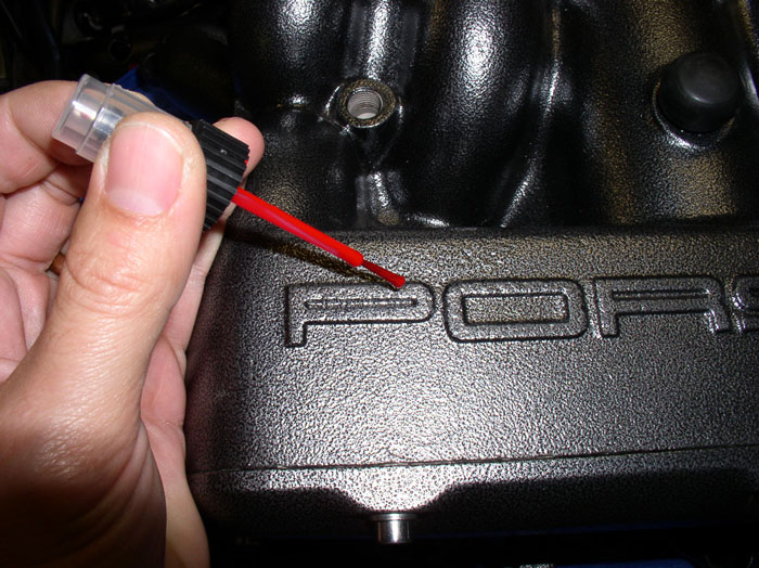
I used automotive touch up paint you buy at an automotive parts store or Wal-Mart in this case. For the red letters, I used a GM color #519 "Victory Red". I also bought a variety of paint brushes thinking I would certainly have the perfect brush to apply paint. However,.....
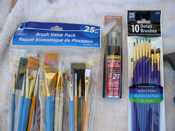
I found the applicator brush that came with the touch-up paint to work very nicely. So I used it. I applied 3 coats of the touch-up paint. Let the paint dry 30-60 minutes between coats ensuring paint is dry to the touch (not tacky) before applying next coat. I focused on painting the "flat" of the recessed lettering and didn't paint the "walls" of the recessed letters.
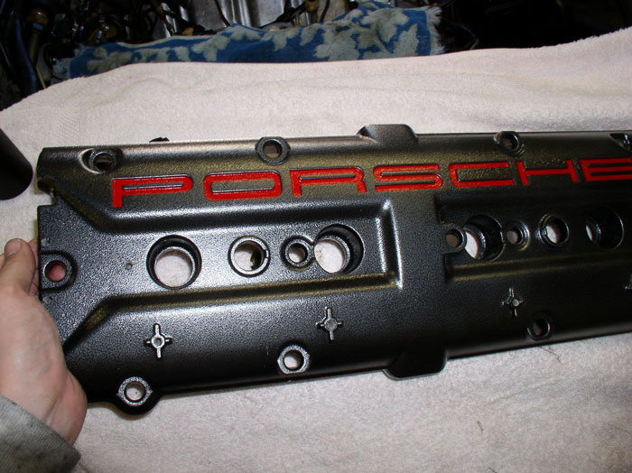
When done, it should look something like this.
Next, the intake lettering. Start by rouging the surface of the letters with 150 grit sandpaper as with the cam cover letters.
Wipe the dust off the letter surfaces.
Then apply the paint as on the cam covers. Again, I used 3 coats of paint and tried to stay on the flat of the letter only.
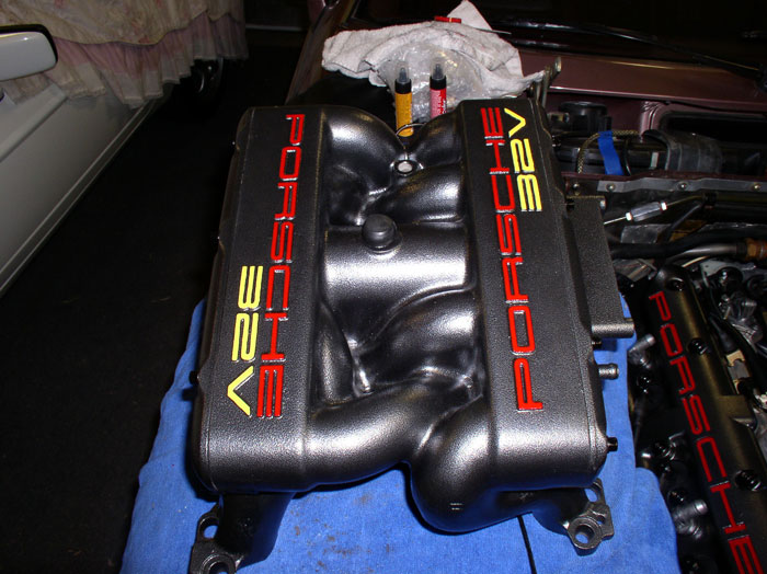
When done, it should look something like this. I used "Ford Chrome Yellow" on the "32V" letters. I thought the yellow would match the other yellow highlights under the hood (e.g., oil filler cap, oil dipstick, yellow decals).
continued.....
As you lay in the gasket into the side cover channel, notice the rubber tabs on the gasket - designed to hold the gasket in place. Therefore, no adheasive/sealant is required on these gaskets.
Next, position the cover with gasket installed onto the intake and install the 5mm allen head bolts. Torque the bolts to 8 ftlbs or 96 inch lbs.
If you decide to paint the lettering on the intake and cam covers and you will be painting over the powder coat surface, you will need to prepare the cam cover and intake surfaces for the paint. I used 150 grit sandpaper. Cut a strip approximately 1/4" wide and about 6" long.
Fold the sandpaper in half lengthwise so it's about 1/8" wide.
Select a small, narrow blade screwdriver ensuring the blade fits between the recessed lettering grooves.
Bend the sandpaper strip over the tip of the screwdriver as pictured and lightly sand the "flat" of the letters on the cam covers. No need to try to remove the existing powder coat or painted surface. The objective is to simply roughen up the surface so the paint will bond better.
After the light sanding, use a damp (not wet) terry cloth rag to wipe the freshly sanded letters clean of dust.
I used automotive touch up paint you buy at an automotive parts store or Wal-Mart in this case. For the red letters, I used a GM color #519 "Victory Red". I also bought a variety of paint brushes thinking I would certainly have the perfect brush to apply paint. However,.....
I found the applicator brush that came with the touch-up paint to work very nicely. So I used it. I applied 3 coats of the touch-up paint. Let the paint dry 30-60 minutes between coats ensuring paint is dry to the touch (not tacky) before applying next coat. I focused on painting the "flat" of the recessed lettering and didn't paint the "walls" of the recessed letters.
When done, it should look something like this.
Next, the intake lettering. Start by rouging the surface of the letters with 150 grit sandpaper as with the cam cover letters.
Wipe the dust off the letter surfaces.
Then apply the paint as on the cam covers. Again, I used 3 coats of paint and tried to stay on the flat of the letter only.
When done, it should look something like this. I used "Ford Chrome Yellow" on the "32V" letters. I thought the yellow would match the other yellow highlights under the hood (e.g., oil filler cap, oil dipstick, yellow decals).
continued.....
01-24-2009, 10:20 AM
#87
Rennlist Member
Dwayne,
You really are da man! I thought your trick for pressing in the flappy bearing was excellent.
I just wanted to add, since the part of the hall sensor that's most likely to fail is the connector end. It's possible to replace just the connector end without removing valve covers. So another time to look at your hall sensor connector is while doing a TB job.
01-24-2009, 02:18 PM
#89
Addict
Lifetime Rennlist
Member
Lifetime Rennlist
Member
Ive got a very small leak as far as i can tell. i used soapy water around some areas and got it to bubble at the front where my SC mates to the manfiold. Prety minor and im notgoing to mess with it until i take it off again later for some other reason.
I would like to be able to have smoke pass though the intake system and then it would be easier to see exactly where leaks are occuring. Any one done that?
thanks again for the write up and showing the device you made.
Also...i added a regulator to the line that feeds the schraeder valve on the tester..i set it for about 4 psi....this way ,if there was a leak it would continue to pressurize the intake system while I looked around for it. Opposed to pressurizing it , then having it leak out right away....then having to pressureize again....over an over.
01-24-2009, 06:30 PM
#90
Basic Sponsor
Rennlist
Site Sponsor
Rennlist
Site Sponsor
Dwayne & Tony,
I have been asked to put together a test kit for those overseas who do not have the luxury of a Home Depot or for those who are challenged with shopping 8>)
Found everything at HD apart from the gauge and fitting - maybe not available in Texas.
Can you be more specific with name and part number or a squew (spelling) number?
Tony,
What about the regulator? Can you share the info on what you used for those less technically advanced?
Picture maybe?
Thanks,
Roger