'87 Intake Removal, Repairs, Installation Procedure (w/pics)
 01-18-2009, 12:22 AM
#31
Rennlist Member
Thread Starter
Join Date: Sep 2007
Location: Ridgecrest, California
Posts: 1,363
Likes: 0
Received 143 Likes
on
28 Posts
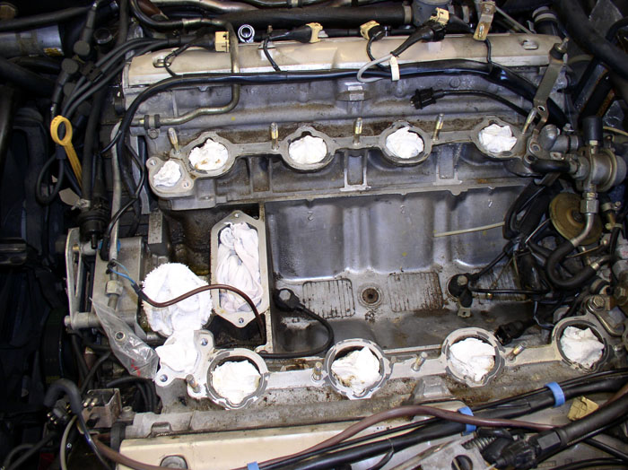
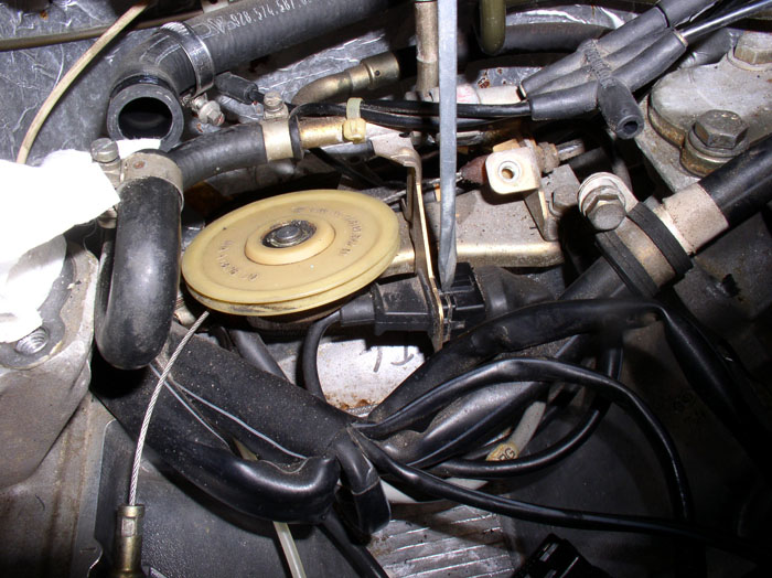
The last thing remaining to include in the intake refresh for powder coating are the cam covers. At this point, the engine should look something like this.
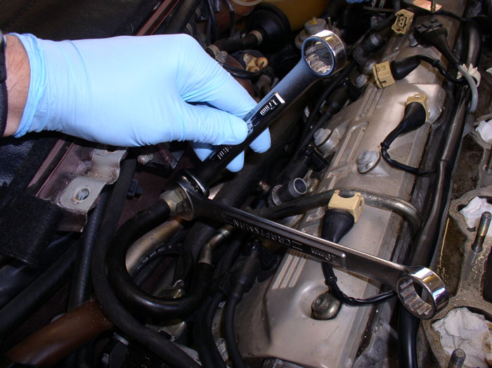
Start by disconnecting the fuel supply line at the passenger fender wall. Use a 19mm wrench to counterhold and a 17mm wrench to loosen the compression nut on the metal side of the fuel line. Use a towel under the connection to catch escaping fuel. After the line is disconnected, remove the fuel line. Also, cap the fuel supply line with a vacuum plug. I didn't cap mine right away but did later on.
I disconnected the fuel vapor solenoid so I could get the hose out of the way and be able to maneuver the harness more freely. I also knew I'd be needing to disconnect if for the TB/WP job coming up next so now seemed like a good time.
Next, disconnect the brake booster to vacuum ventri hose on the driver's side at the brake booster using a phillips screwdriver and remove the hose.
Remove all 8 spark plug wires at the spark plugs. First, disconnect the spark plug wire harness clamps from the hold down brackets on the cam cover. Then pull the plug connectors from the spark plugs as shown. Finally, lay the wires at the front of the engine out of the way.
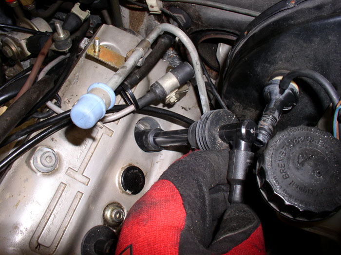
You can begin loosening (but not removing) the cam cover bolts starting with the driver's side. There are 13 bolts. Each is a 5mm allen head bolt. I found the allen socket with extension to work well for the easily accessed bolts - the top and middle bolts.
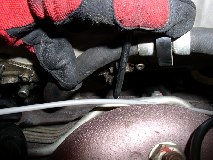
The lower 4 bolts are a little more difficult. The front one you can get at with the socket with no extension.
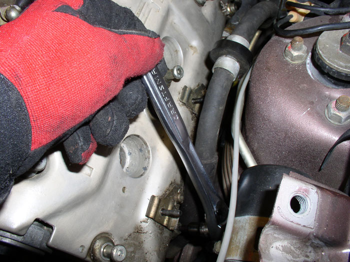
For the next two (middle) lower bolts, I had to use a 5mm allen key wrench. Unfortunately, this goes slow since you can only turn the bolts about 1/3 of a turn at a time while holding the Power Steering hose out of the way. But be patient, take breaks and you will get it to the point where you can loosen the final distance with your fingers.
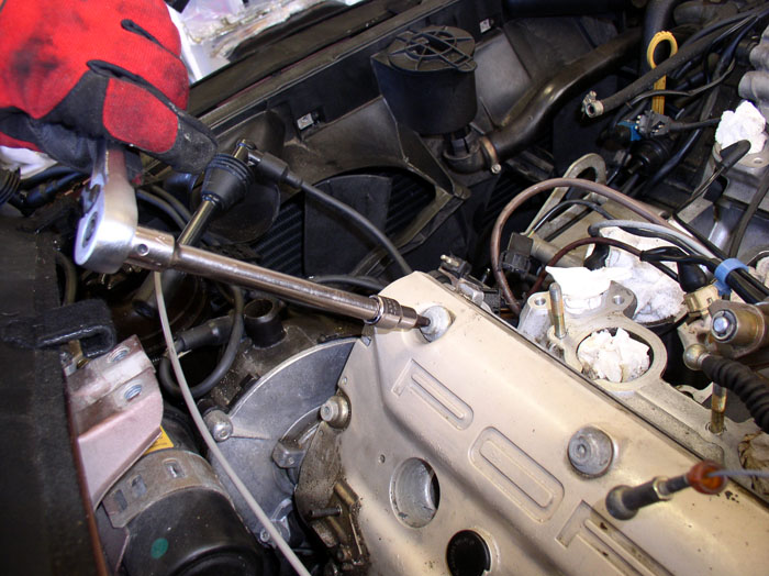
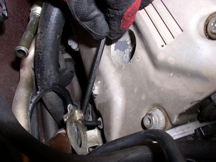
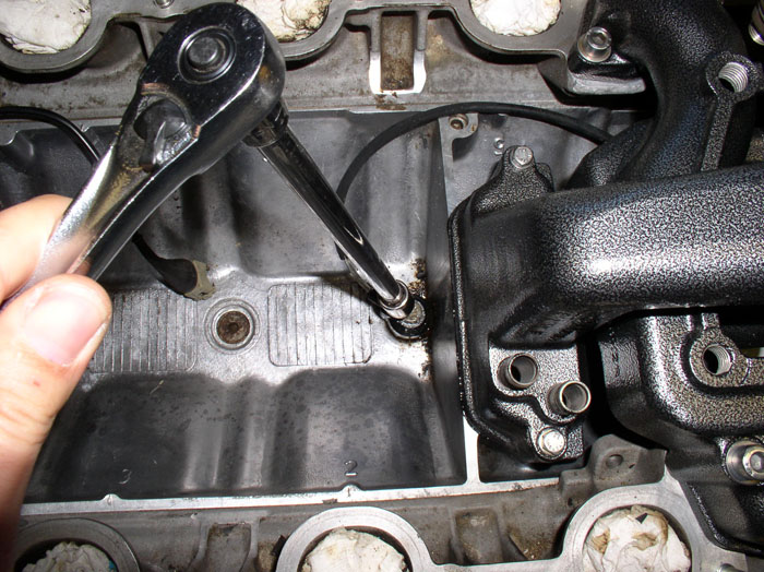
The rear, bottom bolt can be accessed using the allen socket with universal elbow and extension, as pictured.
With all 13 bolts loosened, you can use a screwdriver to lever off the casting tab on the head (as pictured) to carefully pry the cam cover up.
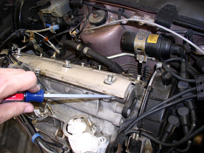
Once the cover is broke free, you can maneuver it up and away from the head being careful not to drop anything into the exposed cam workings below.
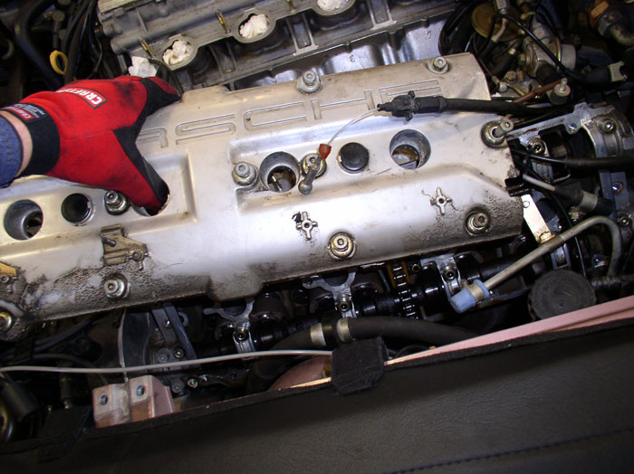
Now you can inspect the cam workings to make sure nothing foreign dropped in.
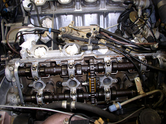
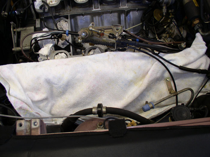
And immediately cover the exposed cams with a clean towel. Place cables on top of the towel.
Now the passenger side. I found it necessary to remove the air pump diverter valve. Start by removing the two 10mm bolts that secure the valve to the mounting bracket. A gear wrench works well here.
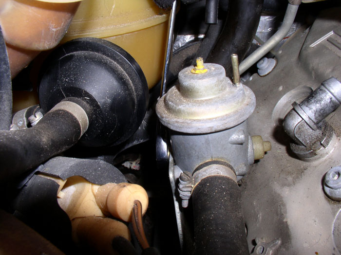
Next, loosen the bottom hose clamp with a flat blade screwdriver and lift up on the diverter valve to separate it from the lower hose.
continued......
Start by disconnecting the fuel supply line at the passenger fender wall. Use a 19mm wrench to counterhold and a 17mm wrench to loosen the compression nut on the metal side of the fuel line. Use a towel under the connection to catch escaping fuel. After the line is disconnected, remove the fuel line. Also, cap the fuel supply line with a vacuum plug. I didn't cap mine right away but did later on.
I disconnected the fuel vapor solenoid so I could get the hose out of the way and be able to maneuver the harness more freely. I also knew I'd be needing to disconnect if for the TB/WP job coming up next so now seemed like a good time.
Next, disconnect the brake booster to vacuum ventri hose on the driver's side at the brake booster using a phillips screwdriver and remove the hose.
Remove all 8 spark plug wires at the spark plugs. First, disconnect the spark plug wire harness clamps from the hold down brackets on the cam cover. Then pull the plug connectors from the spark plugs as shown. Finally, lay the wires at the front of the engine out of the way.
You can begin loosening (but not removing) the cam cover bolts starting with the driver's side. There are 13 bolts. Each is a 5mm allen head bolt. I found the allen socket with extension to work well for the easily accessed bolts - the top and middle bolts.
The lower 4 bolts are a little more difficult. The front one you can get at with the socket with no extension.
For the next two (middle) lower bolts, I had to use a 5mm allen key wrench. Unfortunately, this goes slow since you can only turn the bolts about 1/3 of a turn at a time while holding the Power Steering hose out of the way. But be patient, take breaks and you will get it to the point where you can loosen the final distance with your fingers.
The rear, bottom bolt can be accessed using the allen socket with universal elbow and extension, as pictured.
With all 13 bolts loosened, you can use a screwdriver to lever off the casting tab on the head (as pictured) to carefully pry the cam cover up.
Once the cover is broke free, you can maneuver it up and away from the head being careful not to drop anything into the exposed cam workings below.
Now you can inspect the cam workings to make sure nothing foreign dropped in.
And immediately cover the exposed cams with a clean towel. Place cables on top of the towel.
Now the passenger side. I found it necessary to remove the air pump diverter valve. Start by removing the two 10mm bolts that secure the valve to the mounting bracket. A gear wrench works well here.
Next, loosen the bottom hose clamp with a flat blade screwdriver and lift up on the diverter valve to separate it from the lower hose.
continued......
 01-18-2009, 01:20 AM
#32
Rennlist Member
Thread Starter
Join Date: Sep 2007
Location: Ridgecrest, California
Posts: 1,363
Likes: 0
Received 143 Likes
on
28 Posts
You can remove the spark plug harness brackets from the cam cover using a 4mm allen key wrench. There are two brackets on each cam cover.
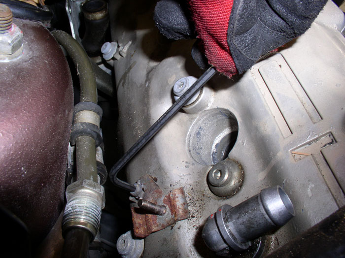
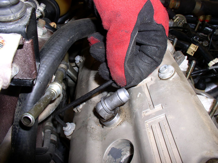
Like the driver's side, there are 13 5mm bolts to loosen on the passenger side. The top row and middle row of cam cover bolts can be easily accessed with the allen socket as before. The bottom 4 require a little extra work. The front bolt can be accessed using a 5mm allen key wrench and can be loosened with the engine lift bracket in place. It will take patience since you can only turn the bolt about a 1/4 turn at a time.
The next bolt in line at the bottom row can be accessed with the allen key wrench - with patience.
The last bolt on the bottom row can be accessed with the allen socket, universal elbow and extension.
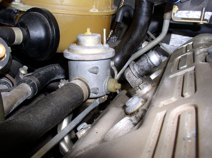
To get at the third bolt on the bottom row. I removed the air diverter valve bracket from the head. It's attached to the head using two 13mm bolts that can be accessed from underneath the car using long extensions (12" and 6") and universal elbow. After the bracket is unattached from the head, you can push it out of the way while you access the cam bolt using the allen socket, extension and universal elbow.
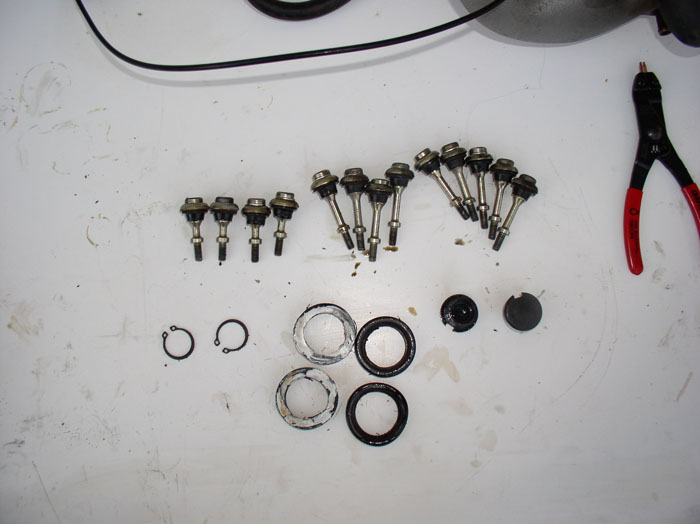
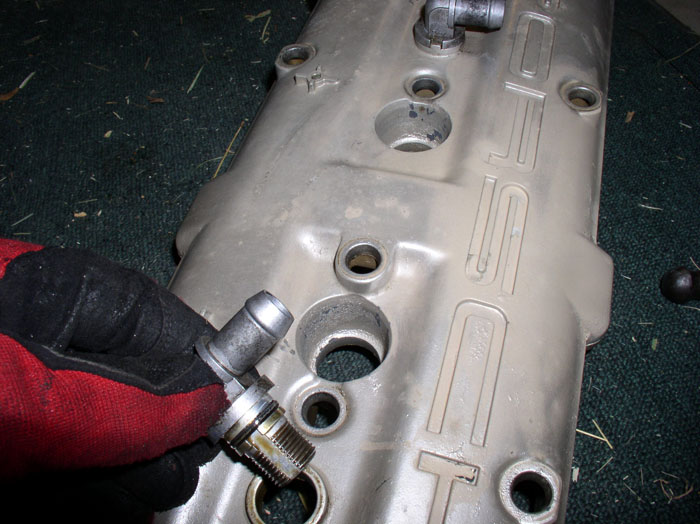
Now you can break loose and manuever the cam cover off the head in the same fashion as on the driver's side. Remember to cover the exposed cams with a clean towel. With both cam covers off, you can remove the bolts an other components in preparation for powder coating. Start with removing the bolts.There are 3 parts to each bolt - the shoulder bolt itself, an umbrella cap washer, and a rubber thrust washer. The exception is there are 6 bolts that have sealing rings between the bolt head and umbrella washer. Note that these six are the 4 bolts at the bottom row of the cam cover and the two end bolts of the middle row. As noted by Dave C. and Bill Ball, you may not find these sealing rings on your cam cover if you have an '89 or newer S4. They seem to be common on '87 and even '88. If you do find them on your cam cover and they are not in the locations described above, and you are certain that your cam covers have never been removed since factory installation, note the location of the bolts that have the rings so you can put them back as the factory installed them (THANKS Dave and Bill!). Otherwise follow the pattern described above for re-installation as it matches the factory service bulletin. Finally, note that 4 of the 13 bolts are shorter than the others. These 4 bolts go into the four corner holes in the cam cover.
The other bolts do not have the sealing rings.
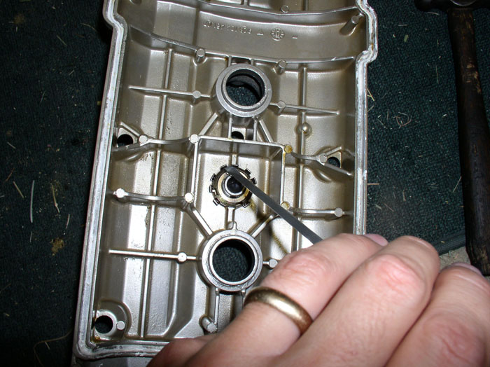
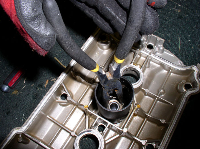
On the driver's side cam cover, remove the breather hole plugs by first removing the circlip that secures the plug to the cover. Use appropriately sized circlip pliers. There are two of these.
When the clip is removed the plugs simply pop out. Each plug seals with an o-ring - which is on the order list. Also, remove the 4 rubber spark plug sealing gaskets from the cam cover. Note that the sealing gaskets have a sealant (white in this case) applied to them.
Here's the items you should have removed from the driver's side cover. All will be reused except for the breather hold plug o-rings, spark plug sealing gaskets, and cam cover bolt thrust (rubber) washers.
For the passenger side cam cover, the two breather elbows use a different means of attachment. Each uses a nut with locking tine washer as shown. Look at the nut closely and you will see a notch cut out and a tine from the washer bent down to lock it into place. You can bend the tine up that is locking the nut in place with a flat blade screwdriver.
Then use pliers to loosen and remove the nut. Then remove the tined washer.
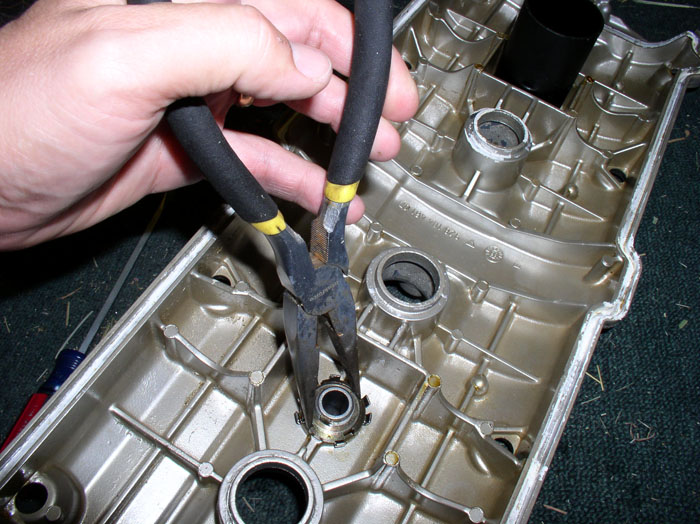
The elbow can then be removed from the top side of the cover. Each elbow also seals with an o-ring that is the same size as the breather hole plugs removed from the Driver's side cam cover.
The rear elbow removal is slightly complicated by the existence of a tube surrounding the nut and tine washer. The removal process is the same as the other elbow. There is enough room to pry away the locking tine and also room enough to use a pair of pliers in the tube to loosen and remove the nut. Proceed with removing the nut, tined washer, tube and elbow.
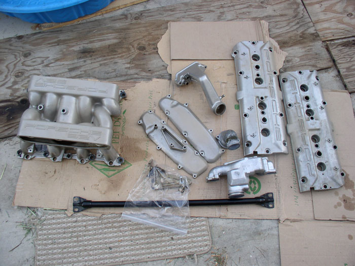
Now the cam covers as well as the other components of the intake refresh are ready for the powder coaters. Here's all the components I sent to Olympic Coatings in southern California. I even included the cross brace and the cam cover bolts and umbrella washers.
continued....
Like the driver's side, there are 13 5mm bolts to loosen on the passenger side. The top row and middle row of cam cover bolts can be easily accessed with the allen socket as before. The bottom 4 require a little extra work. The front bolt can be accessed using a 5mm allen key wrench and can be loosened with the engine lift bracket in place. It will take patience since you can only turn the bolt about a 1/4 turn at a time.
The next bolt in line at the bottom row can be accessed with the allen key wrench - with patience.
The last bolt on the bottom row can be accessed with the allen socket, universal elbow and extension.
To get at the third bolt on the bottom row. I removed the air diverter valve bracket from the head. It's attached to the head using two 13mm bolts that can be accessed from underneath the car using long extensions (12" and 6") and universal elbow. After the bracket is unattached from the head, you can push it out of the way while you access the cam bolt using the allen socket, extension and universal elbow.
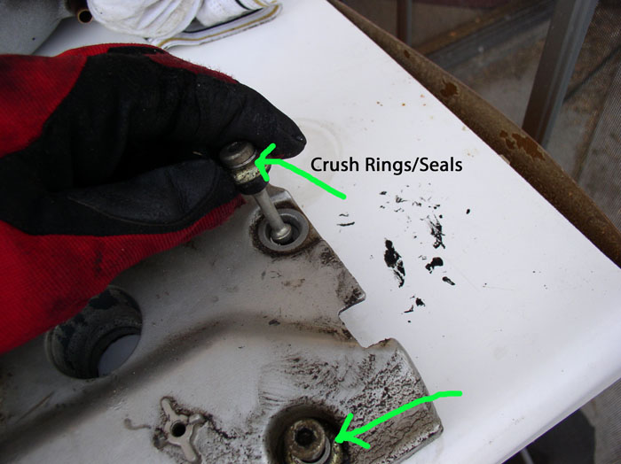
Now you can break loose and manuever the cam cover off the head in the same fashion as on the driver's side. Remember to cover the exposed cams with a clean towel. With both cam covers off, you can remove the bolts an other components in preparation for powder coating. Start with removing the bolts.There are 3 parts to each bolt - the shoulder bolt itself, an umbrella cap washer, and a rubber thrust washer. The exception is there are 6 bolts that have sealing rings between the bolt head and umbrella washer. Note that these six are the 4 bolts at the bottom row of the cam cover and the two end bolts of the middle row. As noted by Dave C. and Bill Ball, you may not find these sealing rings on your cam cover if you have an '89 or newer S4. They seem to be common on '87 and even '88. If you do find them on your cam cover and they are not in the locations described above, and you are certain that your cam covers have never been removed since factory installation, note the location of the bolts that have the rings so you can put them back as the factory installed them (THANKS Dave and Bill!). Otherwise follow the pattern described above for re-installation as it matches the factory service bulletin. Finally, note that 4 of the 13 bolts are shorter than the others. These 4 bolts go into the four corner holes in the cam cover.
The other bolts do not have the sealing rings.
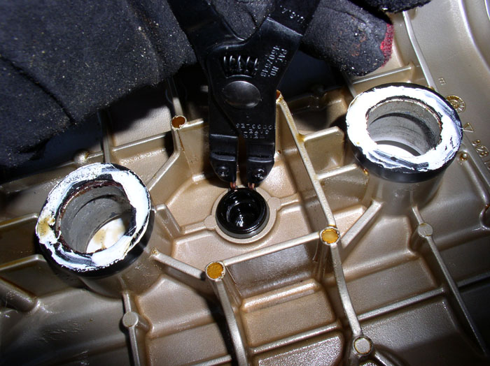
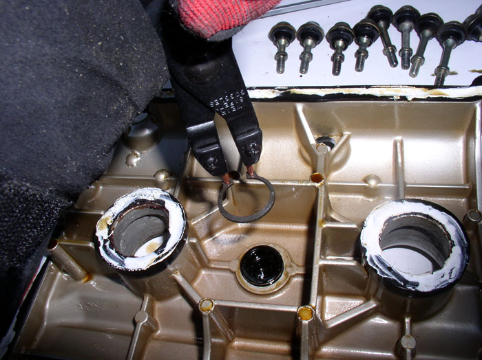
On the driver's side cam cover, remove the breather hole plugs by first removing the circlip that secures the plug to the cover. Use appropriately sized circlip pliers. There are two of these.
When the clip is removed the plugs simply pop out. Each plug seals with an o-ring - which is on the order list. Also, remove the 4 rubber spark plug sealing gaskets from the cam cover. Note that the sealing gaskets have a sealant (white in this case) applied to them.
Here's the items you should have removed from the driver's side cover. All will be reused except for the breather hold plug o-rings, spark plug sealing gaskets, and cam cover bolt thrust (rubber) washers.
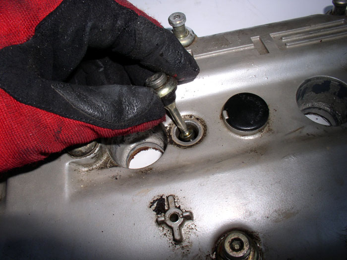
For the passenger side cam cover, the two breather elbows use a different means of attachment. Each uses a nut with locking tine washer as shown. Look at the nut closely and you will see a notch cut out and a tine from the washer bent down to lock it into place. You can bend the tine up that is locking the nut in place with a flat blade screwdriver.
Then use pliers to loosen and remove the nut. Then remove the tined washer.
The elbow can then be removed from the top side of the cover. Each elbow also seals with an o-ring that is the same size as the breather hole plugs removed from the Driver's side cam cover.
The rear elbow removal is slightly complicated by the existence of a tube surrounding the nut and tine washer. The removal process is the same as the other elbow. There is enough room to pry away the locking tine and also room enough to use a pair of pliers in the tube to loosen and remove the nut. Proceed with removing the nut, tined washer, tube and elbow.
Now the cam covers as well as the other components of the intake refresh are ready for the powder coaters. Here's all the components I sent to Olympic Coatings in southern California. I even included the cross brace and the cam cover bolts and umbrella washers.
continued....
01-18-2009, 02:51 AM
#33
Rennlist Member
Thread Starter
Join Date: Sep 2007
Location: Ridgecrest, California
Posts: 1,363
Likes: 0
Received 143 Likes
on
28 Posts
Now that the intake parts are at the Powder Coaters, you can spend some time inspecting and repairing the fuel hoses and heater water valve. First, remove the FPR and FPD assembly by loosening the clamp at the FPR outlet and removing the hose from the FPR.
Then, remove the vacuum elbows from the FPR and the FPD. Now the assembly can be removed for work later on.
Inspect the Fuel return hose that was connected to the FPR. Mine looked fine but when I tried to straighten it, it split. It was at this point I decided to use Roger's fuel hose repair/replacement kit which I already had on hand. However, this particular hose I decided to order since it was moulded for tight radius corners. The rest of the hoses I used Rogers Kit.
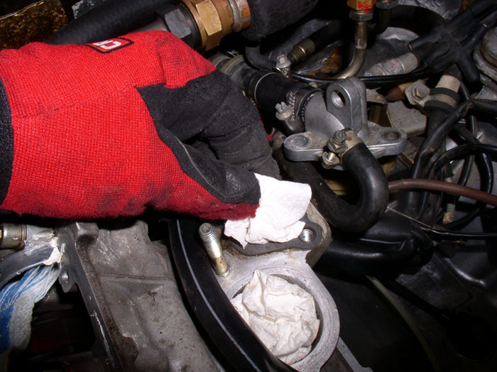
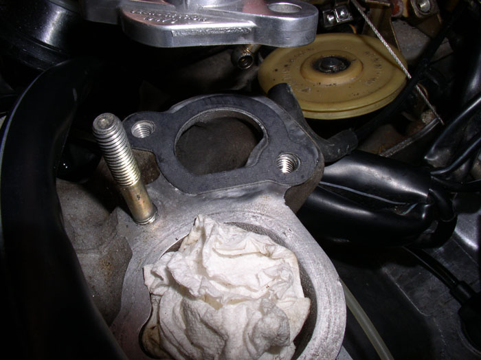
Next, we'll remove the heater water valve and test. Start by removing the remaining 13mm bolt securing the adapter plate to the head. You already removed the other bolt earlier.
Lift the adapter plate away and plug the water port in the head with a clean rag to prevent debris from enter the cooling system.
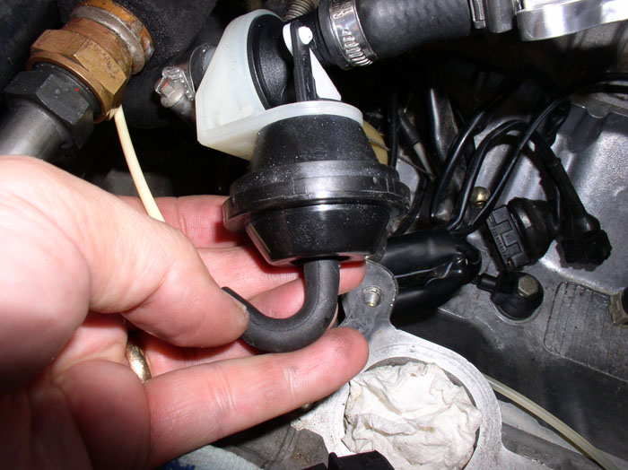
Pull the heater valve assembly forward and disconnect the vacuum elbow from the vacuum diaphram.
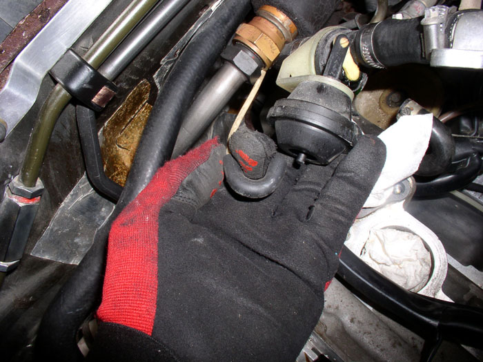
Pull the assembly a little more forward and loosen the clamp at the rear of the assembly with a flat blade screwdriver. Disconnect the hose and remove the assembly.
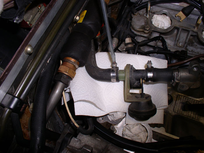
Use a gasket scraper to remove the old gasket from the head and clean the mating surface.
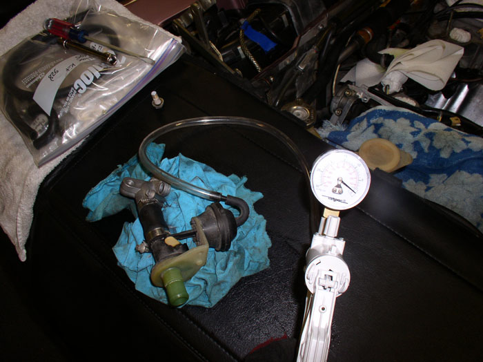
You can connect the vacuum pump to the heater valve diaphram and check the valve for proper operation - it should open and close fully. Also, check to see if it will hold vacuum. You can also fill the tube with water while holding upright to see if it will hold water with the valve closed. I did all of these test on mine and discovered that the diaphram had a slow leak and the valve also leaked water. So the valve went on the parts list.
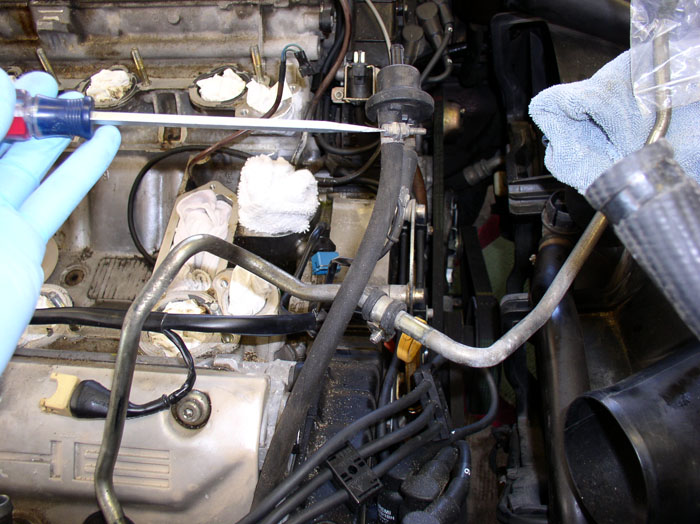
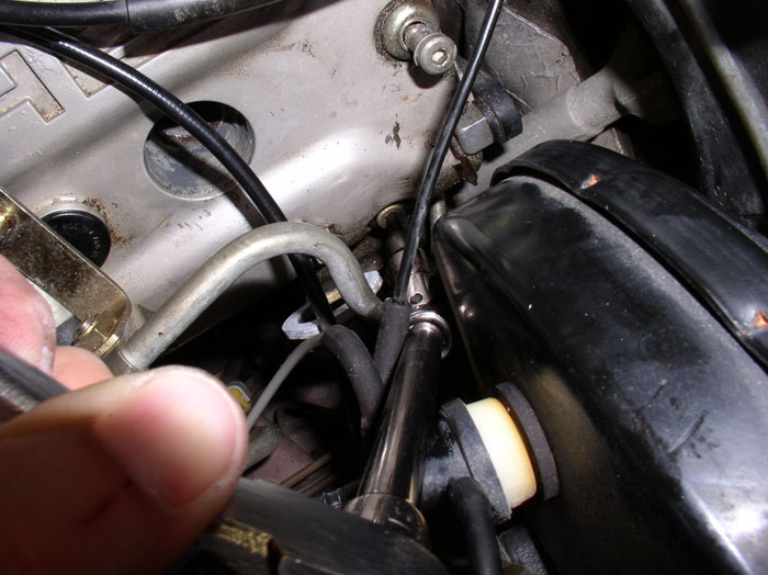
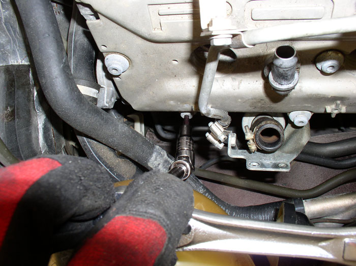
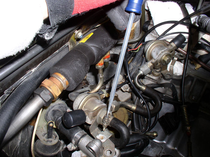
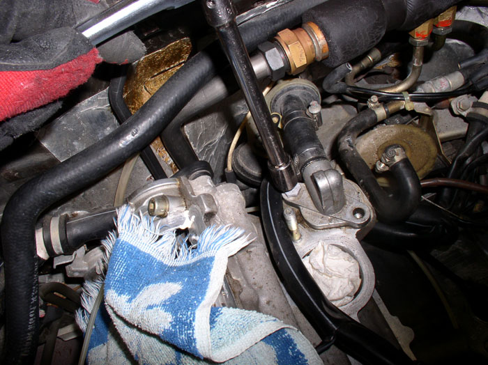
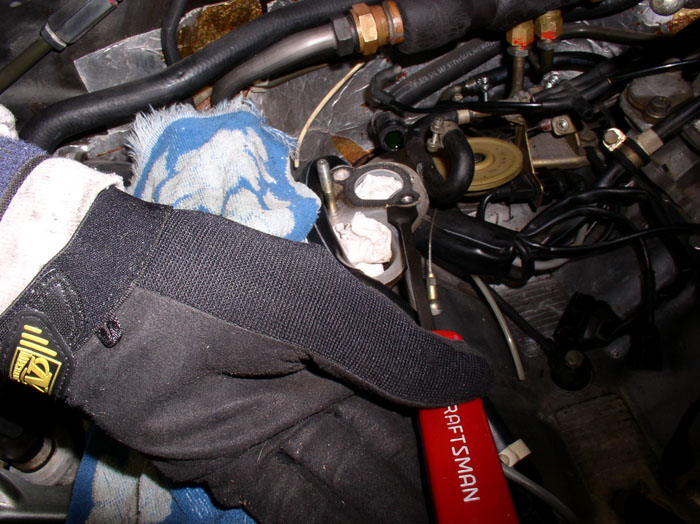
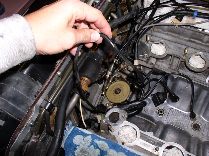
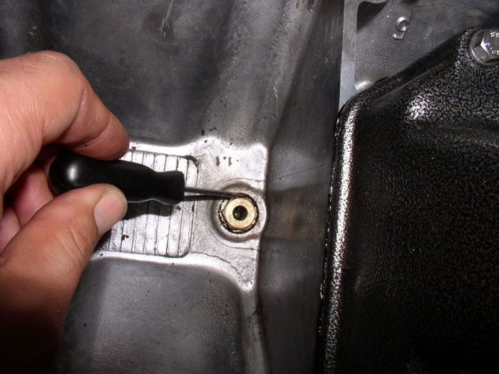
Next, we'll inspect the Crank Position Sensor (CPS) connector plug at the wiring harness. To get to the plug, you will first need to remove the harness clamp located just above the CPS connection to the wiring harness. It's a 10mm bolt that holds the harness clamp. Remove the bolt and push the harness out of the way.
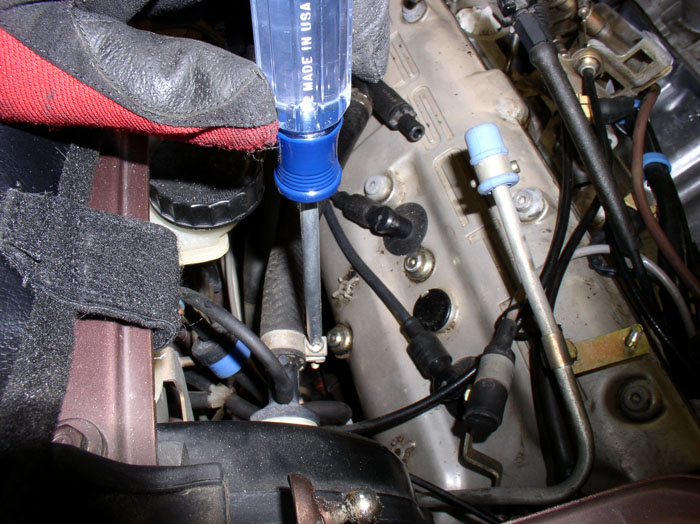
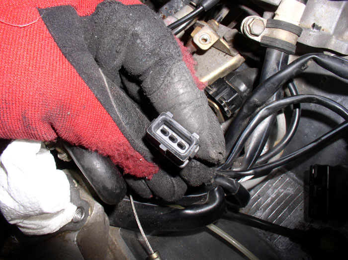
Underneath the harness, you will see the CPS connector to the harness. The harness portion of the connection is pointed to by the screwdriver in the picture. The other side is the plug from the CPS. Disconnect the harness side of the connection by grasping it with your fingers and pulling while rocking side to side.
After the connection is unplugged, you can remove the CPS plug from the bracket and inspect. Unlike the knock sensor plugs, this one was still intact and solid and the electrical blades were clean. Therefore, I decided to keep the original. If you are planning on relacing the sensor, it simply needs to be unbolted from the block. Trace the wire from the CPS plug to the sensor and disconnect if replacement is desired.
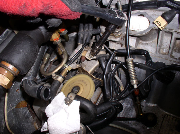
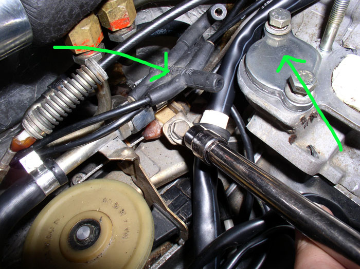
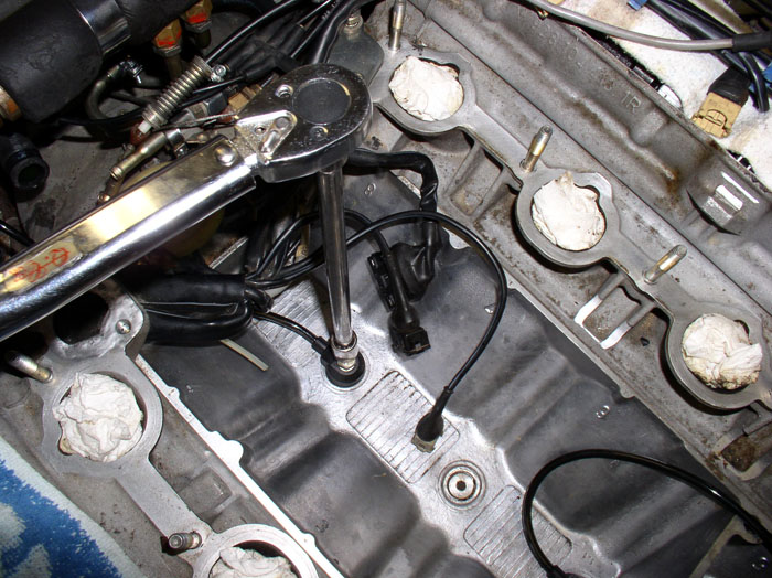
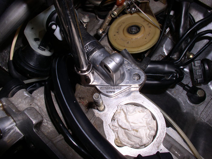
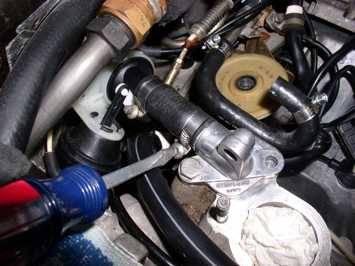
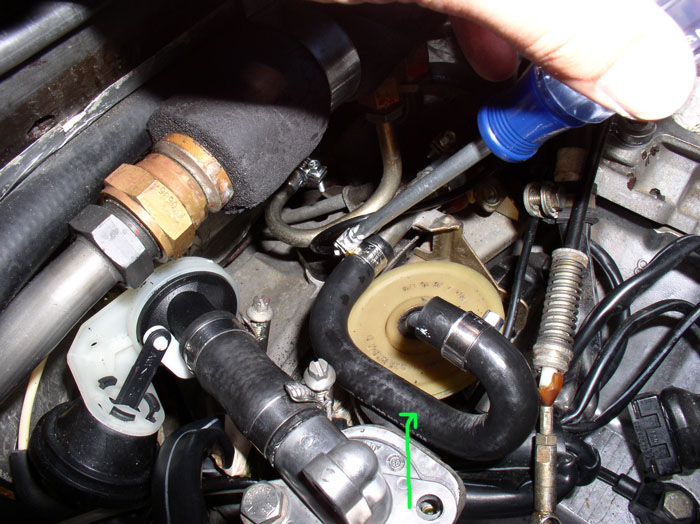
I reconnected the CPS plug to the harness, re-positioned the harness and tightened the 10mm clamping bolt. At this point, it's a good time to replace the gasket on the other coolant port opposite the one that the heater valve is attached to (see right arrow). This is especially true since we broke the 20-year old seal on the gasket when we removed the 13mm bolt that was holding down the Fuel Pressure Damper (FPD) earlier. Remove the remaining (rear) 13mm bolt, remove the plate and plug the port with a clean rag, scrape the old gasket off, clean the mating surface just as you did on the passenger side. You will notice that the rear bolt is 3mm longer than the front bolt (25mm long vs 22mm). Place a new gasket on the head and place the cover plate on the gasket and secure with the two 13mm bolts but don't torque down the bolts yet. The other repair worth doing is replacing the 7-way vacuum manifold (see left arrow). The two lines on the left of the manifold go to the FPR and the transmission. One port is plugged. The two lines on the right side of the manifold go to the rear FPD and the front FPD. One port is plugged. Remove the vacuum lines and plugs and replace the manifold with the new one and reconnect the vacuum lines and plugs.
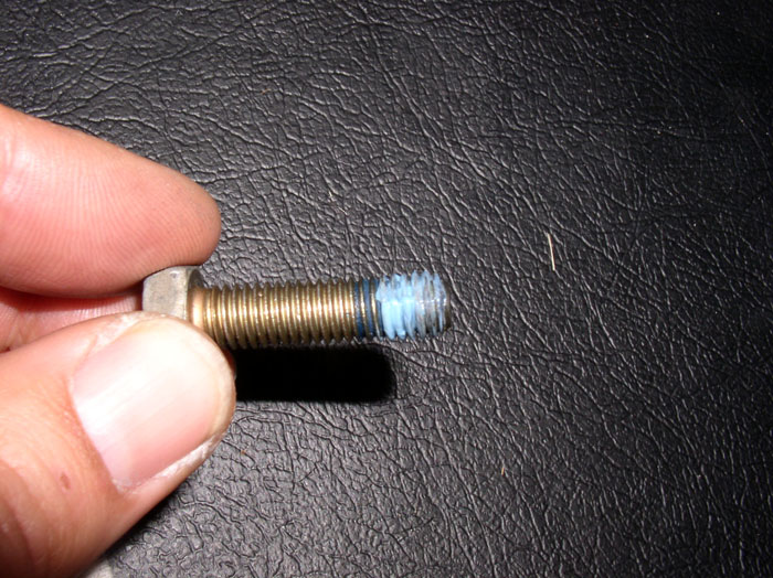
Next, we'll replace the knock sensors. Each is secured with a 13mm bolt. The front knock sensor is easiest. Remove the bolt and the sensor. The bolt was installed with blue threadlocker so it was a little stiff to remove.
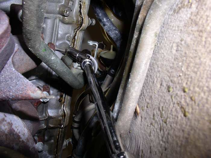
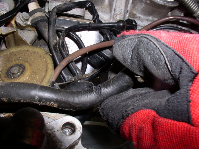
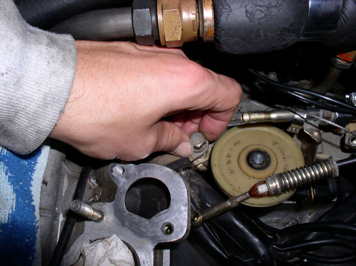
To remove the rear knock sensor, you will need to remove the rear harness clamp because the knock sensor wire is clamped down with the harness. First, remove the FPR outlet hose (the one pictured earlier that was split) by loosening the hose clamp and removing the hose. Then using a 13mm socket with extension, loosen and remove the 13mm bolt holding the harness clamp to the block (shown below).
continued.....
Then, remove the vacuum elbows from the FPR and the FPD. Now the assembly can be removed for work later on.
Inspect the Fuel return hose that was connected to the FPR. Mine looked fine but when I tried to straighten it, it split. It was at this point I decided to use Roger's fuel hose repair/replacement kit which I already had on hand. However, this particular hose I decided to order since it was moulded for tight radius corners. The rest of the hoses I used Rogers Kit.
Next, we'll remove the heater water valve and test. Start by removing the remaining 13mm bolt securing the adapter plate to the head. You already removed the other bolt earlier.
Lift the adapter plate away and plug the water port in the head with a clean rag to prevent debris from enter the cooling system.
Pull the heater valve assembly forward and disconnect the vacuum elbow from the vacuum diaphram.
Pull the assembly a little more forward and loosen the clamp at the rear of the assembly with a flat blade screwdriver. Disconnect the hose and remove the assembly.
Use a gasket scraper to remove the old gasket from the head and clean the mating surface.
You can connect the vacuum pump to the heater valve diaphram and check the valve for proper operation - it should open and close fully. Also, check to see if it will hold vacuum. You can also fill the tube with water while holding upright to see if it will hold water with the valve closed. I did all of these test on mine and discovered that the diaphram had a slow leak and the valve also leaked water. So the valve went on the parts list.
Next, we'll inspect the Crank Position Sensor (CPS) connector plug at the wiring harness. To get to the plug, you will first need to remove the harness clamp located just above the CPS connection to the wiring harness. It's a 10mm bolt that holds the harness clamp. Remove the bolt and push the harness out of the way.
Underneath the harness, you will see the CPS connector to the harness. The harness portion of the connection is pointed to by the screwdriver in the picture. The other side is the plug from the CPS. Disconnect the harness side of the connection by grasping it with your fingers and pulling while rocking side to side.
After the connection is unplugged, you can remove the CPS plug from the bracket and inspect. Unlike the knock sensor plugs, this one was still intact and solid and the electrical blades were clean. Therefore, I decided to keep the original. If you are planning on relacing the sensor, it simply needs to be unbolted from the block. Trace the wire from the CPS plug to the sensor and disconnect if replacement is desired.
I reconnected the CPS plug to the harness, re-positioned the harness and tightened the 10mm clamping bolt. At this point, it's a good time to replace the gasket on the other coolant port opposite the one that the heater valve is attached to (see right arrow). This is especially true since we broke the 20-year old seal on the gasket when we removed the 13mm bolt that was holding down the Fuel Pressure Damper (FPD) earlier. Remove the remaining (rear) 13mm bolt, remove the plate and plug the port with a clean rag, scrape the old gasket off, clean the mating surface just as you did on the passenger side. You will notice that the rear bolt is 3mm longer than the front bolt (25mm long vs 22mm). Place a new gasket on the head and place the cover plate on the gasket and secure with the two 13mm bolts but don't torque down the bolts yet. The other repair worth doing is replacing the 7-way vacuum manifold (see left arrow). The two lines on the left of the manifold go to the FPR and the transmission. One port is plugged. The two lines on the right side of the manifold go to the rear FPD and the front FPD. One port is plugged. Remove the vacuum lines and plugs and replace the manifold with the new one and reconnect the vacuum lines and plugs.
Next, we'll replace the knock sensors. Each is secured with a 13mm bolt. The front knock sensor is easiest. Remove the bolt and the sensor. The bolt was installed with blue threadlocker so it was a little stiff to remove.
To remove the rear knock sensor, you will need to remove the rear harness clamp because the knock sensor wire is clamped down with the harness. First, remove the FPR outlet hose (the one pictured earlier that was split) by loosening the hose clamp and removing the hose. Then using a 13mm socket with extension, loosen and remove the 13mm bolt holding the harness clamp to the block (shown below).
continued.....
01-18-2009, 06:33 AM
#35
Dwayne,
I was alway told never to interupt a master at work.
I you ever need a new vocation you could start up a consultancy as a professional instruction book writer. You would be the best as your system using photographs and saves thousands upon thousands of words.
It is clear and simple.
Looking forward to the continuation of this great work and your future work.
Bills comments + 10.
Tails 1990 928S4 Auto
01-18-2009, 12:51 PM
#37
Rennlist Member
Thread Starter
Join Date: Sep 2007
Location: Ridgecrest, California
Posts: 1,363
Likes: 0
Received 143 Likes
on
28 Posts
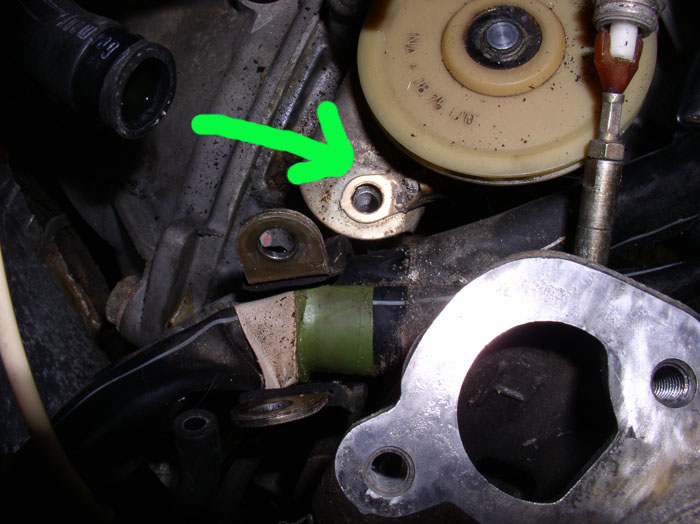
After you've removed the harness clamping bolt (13mm), spread the clamp apart wide enough to manuever the main harness out of the clamp. I had to do this because the knock sensor cable was underneath the harness in the clamp and I couldn't manuever the cable out. The vacuum line from the throttle body to the air diverter valve is also bundled with the harness in this clamp. Also note there is a ground connection under the harness clamp (see the green arrow). We'll clean this shortly. After the harness is out of the clamp....
....you can easily extract the rear knock sensor and sensor cable.
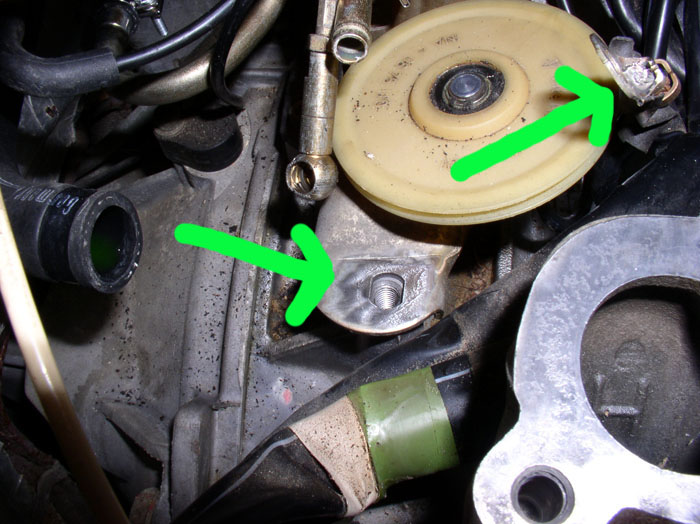
Next, inspect the gound connection under the harness clamp for loose wires or corrosion. Mine seemed snug and the contact surfaces were good but I cleaned it anyway. I used a wire brush on the block side (see left arrow) as well as the ground wire side (right arrow).
Before connecting the new knock sensors, I inspected the area around the threads in the block and noticed some caked dirt. I found a pick to be useful in cleaning this area out before connecting the sensors.
Since I noticed threadlocker on the bolts when removed, I applied a new coat of threadlocker blue to the threads before installation. I assume the threadlocker was used to minimize the chance of loose mounting bolts causing false readings.
Next, position the knock sensor and install the 13mm mounting bolt. For the rear, first lay the knock sensor cable in the harness clamp and take up all the slack between the block connection and the harness clamp (as shown in the picture), giving you maximum cable to work with between the harness clamp and where the cable will plug into the fuel injector harness at the fuel rail. For the front knock sensor, orient the cable so that it points rearward then loop it up and over the block valley wall where it will be connected with the harness later (see picture). Then torque the 13mm bolts to 15 ftlbs or 20 Nm. Finally, insert the wiring harness back into the rear harness clamp ensuring the knock sensor cable and vacuum line are included in the clamp. Ensure the ground wire we cleaned earlier is positioned under the harness clamp as before, then tighten the 13mm clamp bolt down.
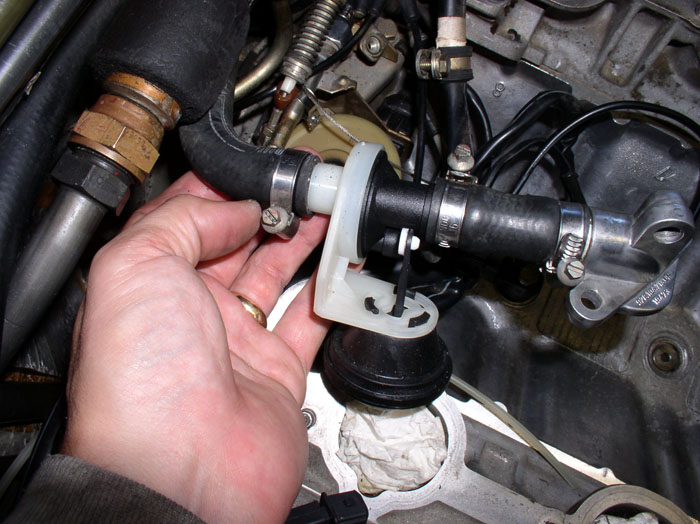
Now we can install the new heater water valve. You will remove the water port adapter plate from the old heater valve assembly then assemble the adapter plate, new short hose if you purchased one, and heater valve as shown (black end toward the block, white end toward the firewall) - but do not tighten any of the hose clamps yet.
Next, attach the vacuum elbow to the heater valve diaphram. I replaced all the elbows with new ones.
Place the gasket on the head mating surface.
Next, we need to orient the heater valve assembly so that it is not rubbing against other components and is not in a bind. To do this, position the adapter plate on the head and install one of the 13mm bolt to hold it in place. Then with the clamps still loose, rotate the assembly so that it does not touch or rub other components - particularly the vacuum elbow. When you are satisfied with the orientation, remove the 13mm bolt, pull the assembly forward and tighten the rear hose clamp. Then re-install the adapter plate to the head, install the 13mm bolt ( but don't torque it down yet)......
....and tighten the remaining two hose clamps on the short hose.
Continued.....
....you can easily extract the rear knock sensor and sensor cable.
Next, inspect the gound connection under the harness clamp for loose wires or corrosion. Mine seemed snug and the contact surfaces were good but I cleaned it anyway. I used a wire brush on the block side (see left arrow) as well as the ground wire side (right arrow).
Before connecting the new knock sensors, I inspected the area around the threads in the block and noticed some caked dirt. I found a pick to be useful in cleaning this area out before connecting the sensors.
Since I noticed threadlocker on the bolts when removed, I applied a new coat of threadlocker blue to the threads before installation. I assume the threadlocker was used to minimize the chance of loose mounting bolts causing false readings.
Next, position the knock sensor and install the 13mm mounting bolt. For the rear, first lay the knock sensor cable in the harness clamp and take up all the slack between the block connection and the harness clamp (as shown in the picture), giving you maximum cable to work with between the harness clamp and where the cable will plug into the fuel injector harness at the fuel rail. For the front knock sensor, orient the cable so that it points rearward then loop it up and over the block valley wall where it will be connected with the harness later (see picture). Then torque the 13mm bolts to 15 ftlbs or 20 Nm. Finally, insert the wiring harness back into the rear harness clamp ensuring the knock sensor cable and vacuum line are included in the clamp. Ensure the ground wire we cleaned earlier is positioned under the harness clamp as before, then tighten the 13mm clamp bolt down.
Now we can install the new heater water valve. You will remove the water port adapter plate from the old heater valve assembly then assemble the adapter plate, new short hose if you purchased one, and heater valve as shown (black end toward the block, white end toward the firewall) - but do not tighten any of the hose clamps yet.
Next, attach the vacuum elbow to the heater valve diaphram. I replaced all the elbows with new ones.
Place the gasket on the head mating surface.
Next, we need to orient the heater valve assembly so that it is not rubbing against other components and is not in a bind. To do this, position the adapter plate on the head and install one of the 13mm bolt to hold it in place. Then with the clamps still loose, rotate the assembly so that it does not touch or rub other components - particularly the vacuum elbow. When you are satisfied with the orientation, remove the 13mm bolt, pull the assembly forward and tighten the rear hose clamp. Then re-install the adapter plate to the head, install the 13mm bolt ( but don't torque it down yet)......
....and tighten the remaining two hose clamps on the short hose.
Continued.....
01-18-2009, 02:05 PM
#38
Rennlist Member
Thread Starter
Join Date: Sep 2007
Location: Ridgecrest, California
Posts: 1,363
Likes: 0
Received 143 Likes
on
28 Posts
I had ordered the moulded hose replacement for the Fuel Pressure Regulator (FPR) and installed it next. I wasn't sure if I was supposed to use the bulk hose in Roger's kit for this hose because of the tight radius so I ordered the replacement. I used Roger's kit for all other fuel hose replacements. You can orient the hose as shown in the picture. However, ensure the top of the fuel hose section pointed at by the green arrow is level with the mating surface of the heater water port on the head adjacent to it. When you re-install the FPR bracket, it has a hose guide that will fit around the FPR return hose and the hose should be oriented this way to fit properly in the guide. Tighten the hose clamp (used clamps from Roger's kit)
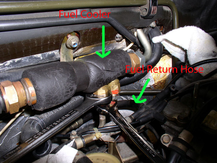
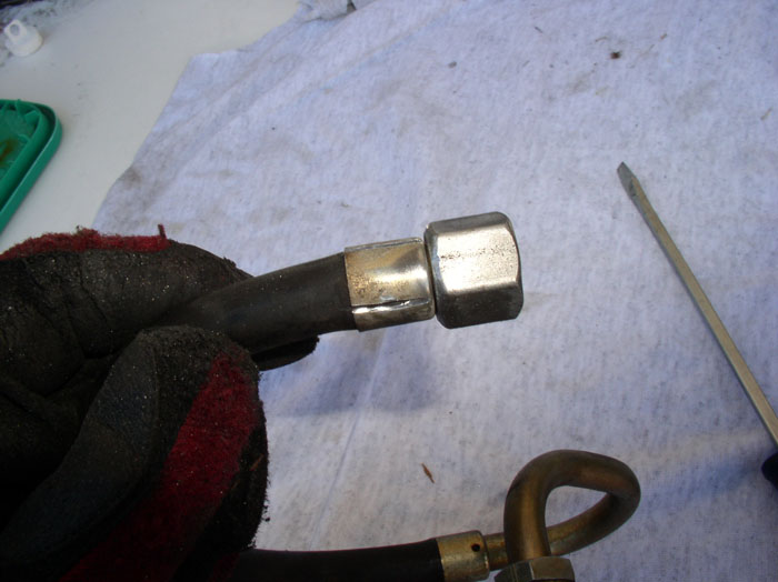
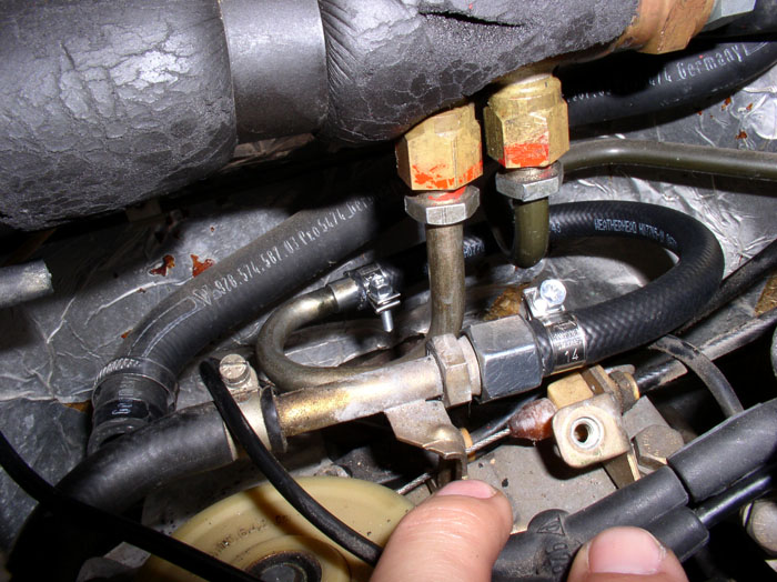
Next, you can replace the fuel return hose that feeds into the fuel cooler. The return hose from the FPR feeds the inlet side of the cooler (shown in the picture) and is the left connection. The right connection from the cooler returns the cooled fuel to the fuel tank. Use a 19mm wrench to counterhold the nut attached to the cooler and a 17mm wrench to loosen the fuel return hose nut. Then, use a 19mm wrench to remove the nut at the other end of the return hose where it connects to the throttle cable and fuel hose engine bracket that's attached to the block. Remove the return hose.
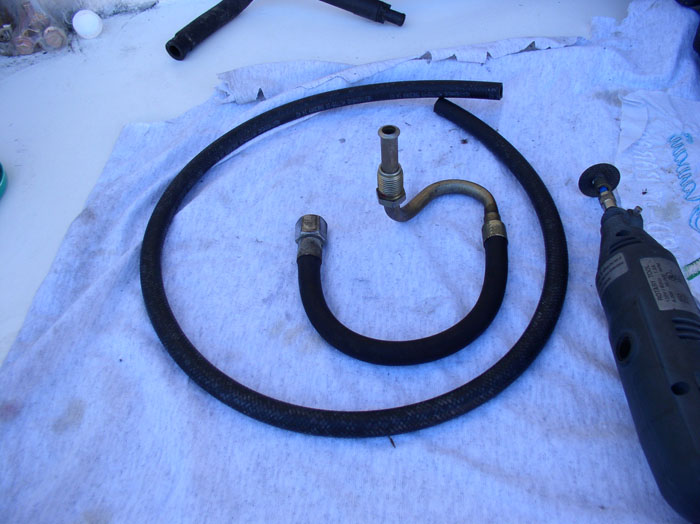
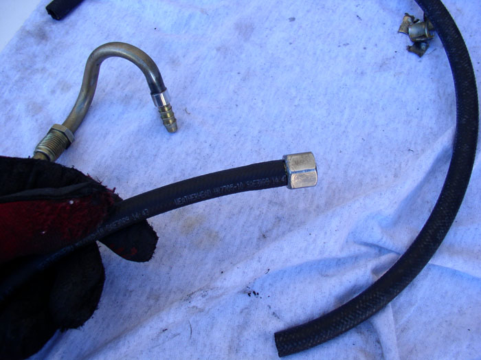
The hose should look like this (see below) along with the bulk hose from Roger's kit. You will wan to save the metal end pieces from the original hose and install them on the bulk hose. I've had real good experiences using the dremel tool with metal cutting wheel attachment as shown.
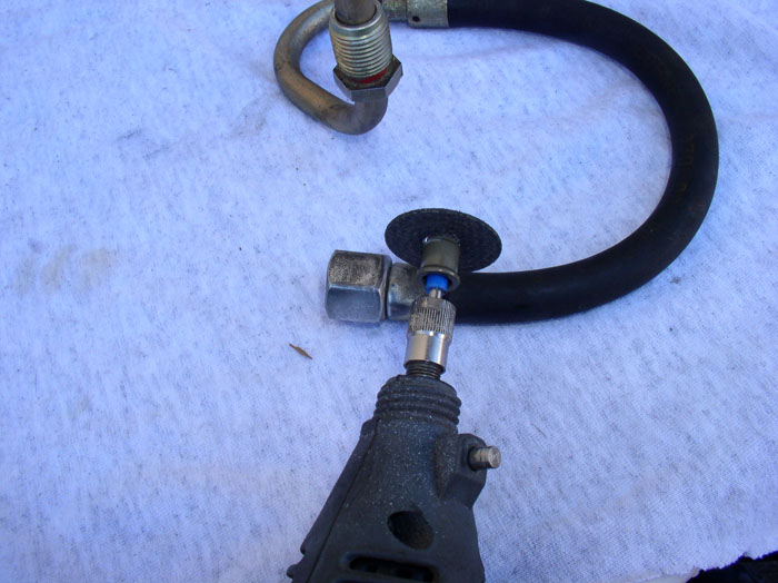
First, carefully cut the metal hose crimping using the dremel. Do not cut too deeply because you don't want to damage the hose barbs on the fitting below the hose. Cut as as close to the nut as you can without cutting touching the nut.
Make two cuts to ease the removal of the hose crimp.
After the incisions are made, use a screwdriver to pry up the metal crimp as shown here.
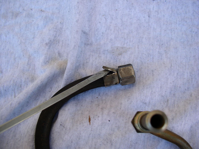
Then use a pair of pliers to remove a portion of the hose crimp.
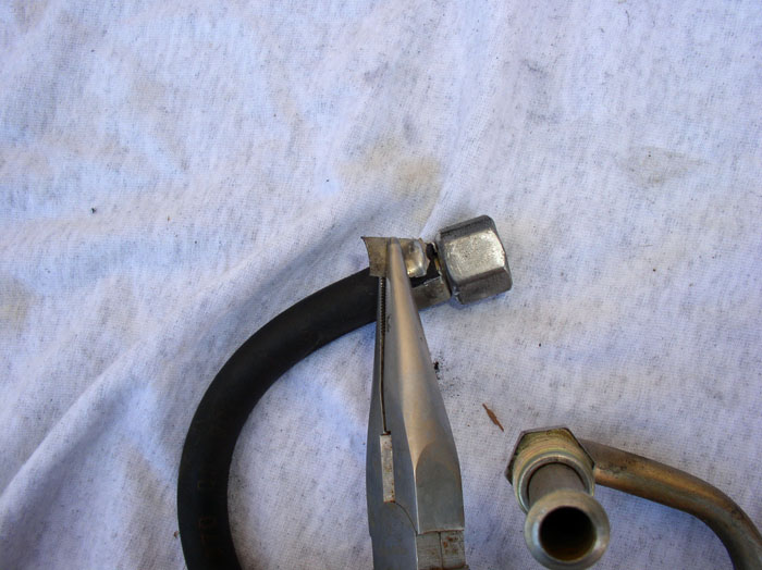
You can then cut through the rubber hose with a utility knife - being careful not to score the barbs on the fitting underneath the hose. Then pull the hose fitting out from the hose. Perform the same operation on the other end of the the hose.
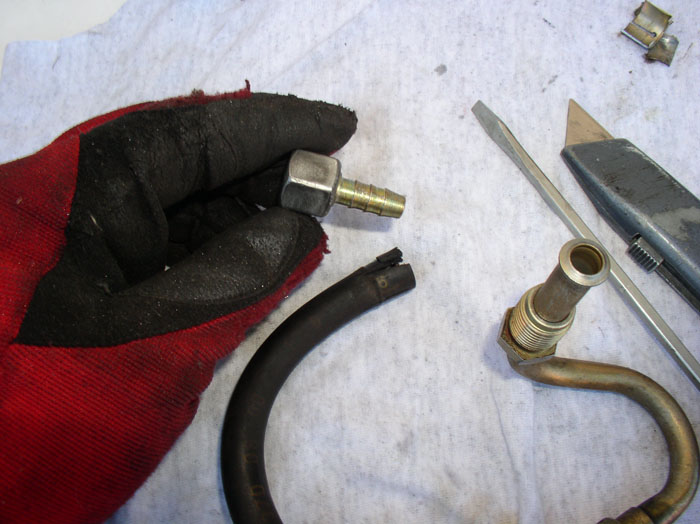
With the old hose removed. Use it to measure out and cut a matching length of the bulk hose from Roger's hose kit. I used a utility knife to cut the hose.
Next, fit the barb with nut on the hose. It was a nice fit - snug and not too tight that it required any special procedures to install.
Now install the two hose clamps oriented so they face inward with the phillips head is facing up as shown. Then attach the tube end of the return hose as shown.
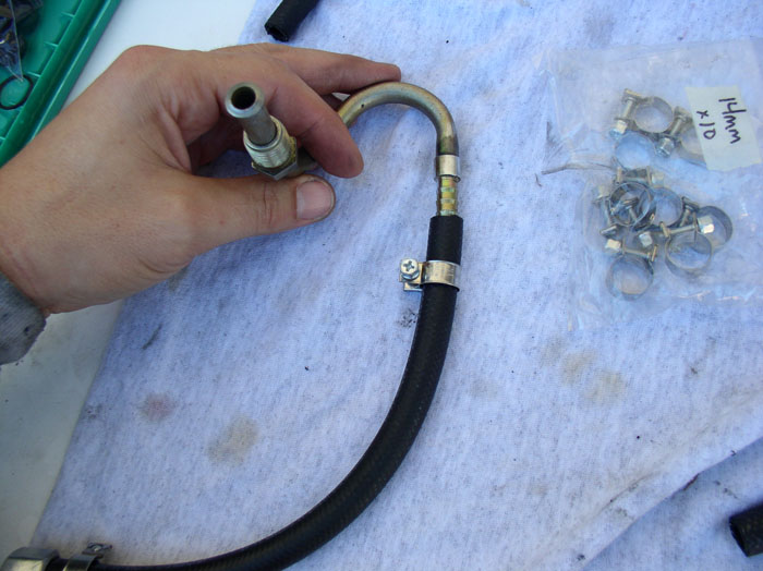
Check the orientation of the clamps so they can be accessed when the hose is installed. Then tighten the clamps.
Re-install the hose at the cooler and the throttle cable/fuel hose engine bracket using the 17mm and 19mm wrenches.
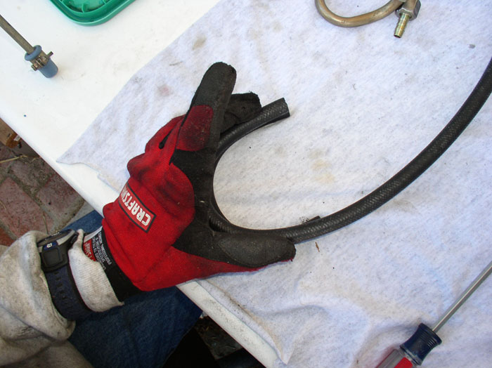
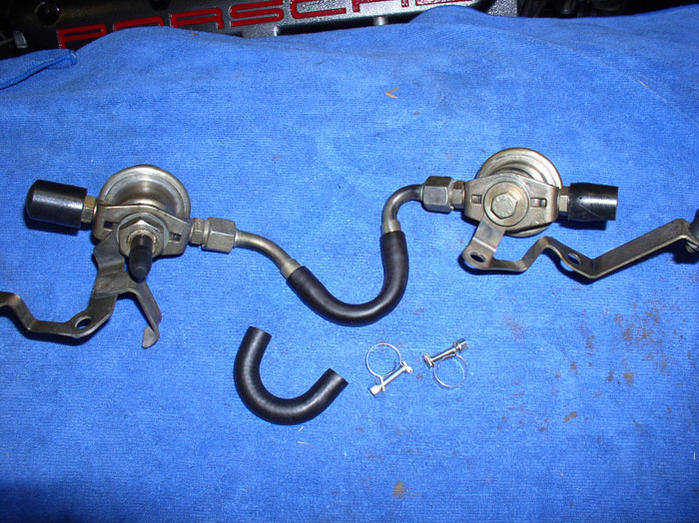
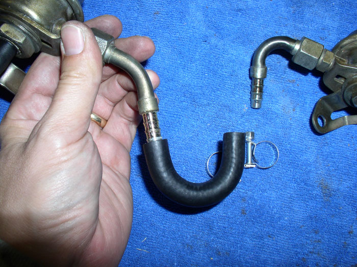
Next, replace the small "U" shaped fuel hose that runs between the rear FPD and FPR. This is a moulded hose that comes with its own clamps with Roger's kit.
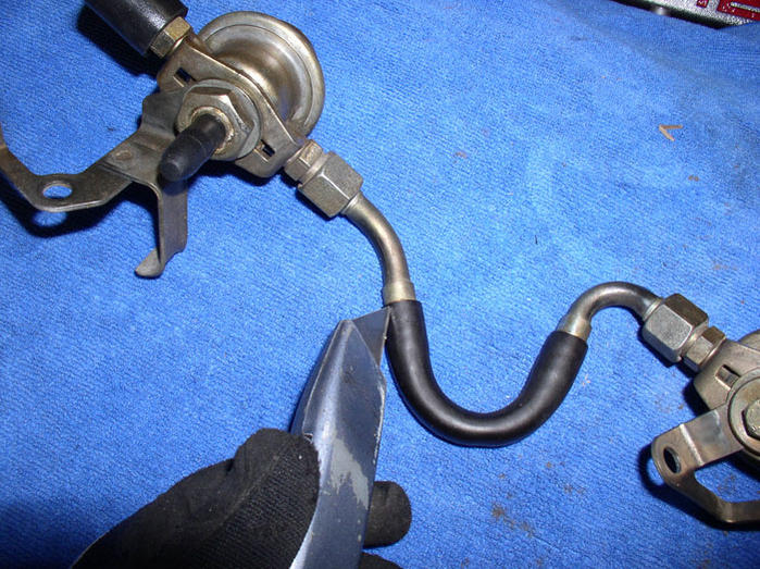
Use a utility knife to carefully cut lengthwise incisions in the rubber hose being careful not to cut too deeply and score the metal barbs underneath the hose.
Continued.....
Next, you can replace the fuel return hose that feeds into the fuel cooler. The return hose from the FPR feeds the inlet side of the cooler (shown in the picture) and is the left connection. The right connection from the cooler returns the cooled fuel to the fuel tank. Use a 19mm wrench to counterhold the nut attached to the cooler and a 17mm wrench to loosen the fuel return hose nut. Then, use a 19mm wrench to remove the nut at the other end of the return hose where it connects to the throttle cable and fuel hose engine bracket that's attached to the block. Remove the return hose.
The hose should look like this (see below) along with the bulk hose from Roger's kit. You will wan to save the metal end pieces from the original hose and install them on the bulk hose. I've had real good experiences using the dremel tool with metal cutting wheel attachment as shown.
First, carefully cut the metal hose crimping using the dremel. Do not cut too deeply because you don't want to damage the hose barbs on the fitting below the hose. Cut as as close to the nut as you can without cutting touching the nut.
Make two cuts to ease the removal of the hose crimp.
After the incisions are made, use a screwdriver to pry up the metal crimp as shown here.
Then use a pair of pliers to remove a portion of the hose crimp.
You can then cut through the rubber hose with a utility knife - being careful not to score the barbs on the fitting underneath the hose. Then pull the hose fitting out from the hose. Perform the same operation on the other end of the the hose.
With the old hose removed. Use it to measure out and cut a matching length of the bulk hose from Roger's hose kit. I used a utility knife to cut the hose.
Next, fit the barb with nut on the hose. It was a nice fit - snug and not too tight that it required any special procedures to install.
Now install the two hose clamps oriented so they face inward with the phillips head is facing up as shown. Then attach the tube end of the return hose as shown.
Check the orientation of the clamps so they can be accessed when the hose is installed. Then tighten the clamps.
Re-install the hose at the cooler and the throttle cable/fuel hose engine bracket using the 17mm and 19mm wrenches.
Next, replace the small "U" shaped fuel hose that runs between the rear FPD and FPR. This is a moulded hose that comes with its own clamps with Roger's kit.
Use a utility knife to carefully cut lengthwise incisions in the rubber hose being careful not to cut too deeply and score the metal barbs underneath the hose.
Continued.....
01-18-2009, 02:20 PM
#39
Rennlist Member
Thread Starter
Join Date: Sep 2007
Location: Ridgecrest, California
Posts: 1,363
Likes: 0
Received 143 Likes
on
28 Posts
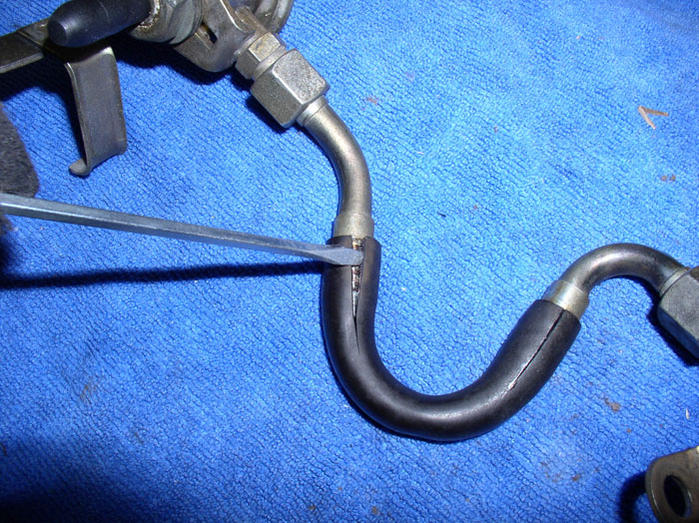
After the incisions are made, use a screwdriver to pry the hose apart enough to allow you to pull the hose off the barbs.
Next, fit one end of the hose to the Fuel Pressure Regulator (FPR) in approximately the same orientation as the old hose.
Slide the two hose clamps onto the hose oriented so that the phillips head is facing up and inward when installed. Then attach the Fuel Pressure Damper (FPD) to the other end of the hose but don't tighten the clamps yet.
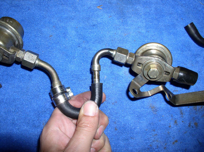
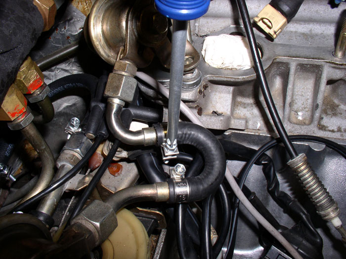
Finally, take the assembly to the engine and place the FPR and FPD brackets over the rear intake mounting studs as they would be installed for a fit check. Rotate the hose and FPR/FPD so that the hose is not in a bind. Then tighten the hose clamps as shown. Remove the assembly afterwards for re-install later.
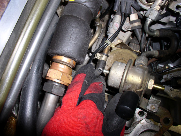
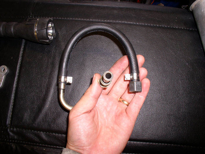
The last bulk hose repair to make is the fuel supply line that runs over the passenger cam cover (pictured below with the new bulk hose intalled). This hose will be installed later. The procedure for replacing this hose is identical as the procedure for the fuel return hose at the fuel cooler we just completed.
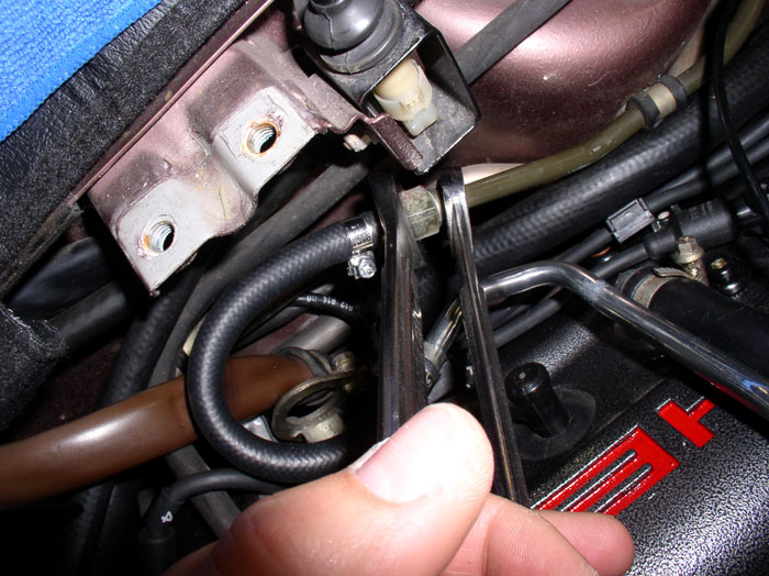
One more hose comes with Roger's kit and it is the front hose that runs from passenger fuel rail to front FPD. It already has fittings on the ends and simply needs to be bolted on. This will be installed when the fuel rails are re-installed.
continued....
Next, fit one end of the hose to the Fuel Pressure Regulator (FPR) in approximately the same orientation as the old hose.
Slide the two hose clamps onto the hose oriented so that the phillips head is facing up and inward when installed. Then attach the Fuel Pressure Damper (FPD) to the other end of the hose but don't tighten the clamps yet.
Finally, take the assembly to the engine and place the FPR and FPD brackets over the rear intake mounting studs as they would be installed for a fit check. Rotate the hose and FPR/FPD so that the hose is not in a bind. Then tighten the hose clamps as shown. Remove the assembly afterwards for re-install later.
The last bulk hose repair to make is the fuel supply line that runs over the passenger cam cover (pictured below with the new bulk hose intalled). This hose will be installed later. The procedure for replacing this hose is identical as the procedure for the fuel return hose at the fuel cooler we just completed.
One more hose comes with Roger's kit and it is the front hose that runs from passenger fuel rail to front FPD. It already has fittings on the ends and simply needs to be bolted on. This will be installed when the fuel rails are re-installed.
continued....
01-18-2009, 02:52 PM
#40
Rennlist Member
Thread Starter
Join Date: Sep 2007
Location: Ridgecrest, California
Posts: 1,363
Likes: 0
Received 143 Likes
on
28 Posts
I'm not familiar with Yamabond but a similar substance was found on the head mating surface where the cam cover gasket seats (particularly at the four corners of the cam cover gasket). It appears to be rubbery like silicone - not sure what was used. But I did re-install with silicone sealant - pictures will come later in this post. THANKS for the question.
01-18-2009, 04:15 PM
#41
Under the Lift
Lifetime Rennlist
Member
Lifetime Rennlist
Member
Minor detail - knock sensor mounting torque is 15 ft-lbs (conversion is 0.74). They are sensitive to torque but I doubt 17 will make any difference, especially considering the accuracy of the torque wrenches most of us use.
As to Yamabond or other sealants on the cam cover gasket, all I have ever seen and done is "goop" in the corners as indicated in the bulletin below. The hardest part is to get the gasket to stay in the cam cover groove as you maneuver the cover back on around obstructions when doing this with the motor in the car. Use some gasket cement to glue it to the cover and make sure it has set well before you attempt to put the cover on. Put some "goop" in the corners of the head as indicated by the "A" arrows, running about an inch up the cam cap and an inch on the head.
As to Yamabond or other sealants on the cam cover gasket, all I have ever seen and done is "goop" in the corners as indicated in the bulletin below. The hardest part is to get the gasket to stay in the cam cover groove as you maneuver the cover back on around obstructions when doing this with the motor in the car. Use some gasket cement to glue it to the cover and make sure it has set well before you attempt to put the cover on. Put some "goop" in the corners of the head as indicated by the "A" arrows, running about an inch up the cam cap and an inch on the head.
01-18-2009, 06:35 PM
#42
Rennlist Member
Join Date: Oct 2003
Location: Saco, Maine/ Scarborough, Maine
Posts: 1,961
Received 546 Likes
on
207 Posts
Dwayne, as usual, unbelievable detail and pixs. I have a WOT switch and knock sensor bad (Thanks to Dave C diagnosis ), and this is my big project in the spring..and I'll be following your instruction every inch of the way.
Thanks for the effort and sharing !!!
Bob Voskian
1989 928 S4 silver/black ( Hibernating in maine at -15 degrees last night!)
2006 BMW X5 3.0i ( great winter daily driver)
Thanks for the effort and sharing !!!
Bob Voskian
1989 928 S4 silver/black ( Hibernating in maine at -15 degrees last night!)
2006 BMW X5 3.0i ( great winter daily driver)
01-18-2009, 07:31 PM
#43
Addict
Rennlist Member
Rennlist Member
Join Date: Apr 2004
Location: Kihei, Hawaii
Posts: 813
Likes: 0
Received 0 Likes
on
0 Posts
Dwayne, awesome writeup and an awesome job.
I've got this project planned for later this winter and will print this for reference. Thanks so much.
If you want to visit central Virginia, I'm sure I could spring for a JetBlue flight!!
I've got this project planned for later this winter and will print this for reference. Thanks so much.
If you want to visit central Virginia, I'm sure I could spring for a JetBlue flight!!
01-18-2009, 09:10 PM
#44
Three Wheelin'
My xmas present
Once again...
 and
and  and
and  01-18-2009, 10:08 PM
#45
Rennlist Member
Thread Starter
Join Date: Sep 2007
Location: Ridgecrest, California
Posts: 1,363
Likes: 0
Received 143 Likes
on
28 Posts
THANK YOU Bill for the correction on Torque for the Knock Sensors. I know now where I went wrong and got 17. 20 Nm is the right number and the conversion is about 14.75 so 15 ftlbs is the number that should be used. I'll correct the posting. THANKS for the catch and helping to improve the quality of the post.