

Seat memory switch bulbs
 06-25-2017, 01:46 PM
#16
Addict
Rennlist Member
Rennlist Member
IMHO, the significant considerations that come into play when diagnosing the switches and lights for the seat/mirrors:
Based on the above and my own experiences, it's more likely that failures of switches (if it's an electrical problem and not a mechanical problem with movement of the switch cap) and especially the LEDs for 1/2/3 are due to bad solder joints at the controller rather than a problem with the switch/indicator assembly. That said, it couldn't hurt to try some contact cleaner on the switches.
A few more notes I have from late 2013 when I was working on this stuff (and note that my main interest at the time was refitting the 1/2/3 backlighting switches with white instead of yellow LEDs, and the memory backlighting switch with a red LED instead of an incandescent bulb):
- The switches only use two of the terminals on the assembly: 1 (encoded signal) and 4 (ground). More details on this are in my notes below.
- The LEDs, as Alan pointed out, are wired separately, with anodes wired to terminals 3, 7, and 5, for switches 1, 2, and 3, respectively (to ground, on terminal 4).
- The seat/mirror controller is known to have a significant problem with the solder joints for the connectors. See the thread I already referenced in post #6 above.
Based on the above and my own experiences, it's more likely that failures of switches (if it's an electrical problem and not a mechanical problem with movement of the switch cap) and especially the LEDs for 1/2/3 are due to bad solder joints at the controller rather than a problem with the switch/indicator assembly. That said, it couldn't hurt to try some contact cleaner on the switches.
A few more notes I have from late 2013 when I was working on this stuff (and note that my main interest at the time was refitting the 1/2/3 backlighting switches with white instead of yellow LEDs, and the memory backlighting switch with a red LED instead of an incandescent bulb):
- I took the opened-up assembly with the connector attached (i.e., just the rectangular box with the PCB and connector, LEDs, and incandescent bulb) and plugged it back into my car so I could determine what constituted normal behavior (I didn't remember some of the details). I discovered that the three LEDs dim with the instrumentation lighting. When the incandescent bulb turns on, it's really slow to light up and slow to shut off again. It's like lighting and blowing out a candle.

- The current limiting resistors for the LEDs are not on the memory switch PCB. They're apparently in the seat control unit.
- Approximating the locations of the LEDs when they're back in their proper position behind the plastic switch tops, I experimented with some white LEDs. I think I'm going to use RL3-W8080 (white, 8000 mcd, 30� beam spread) LEDs for the three memory position backlighting LEDs. RL3-W6045 (white, 6000 mcd, 45� beam spread) works, too, but I think it might waste a little more light around the button face target. Either of these options are considerably brighter than the original yellow LEDs.
- Approximating the location of the incandescent bulb (and using the white plastic light channel), I experimented with the only bright discrete 3mm LED I could find on hand. It was an RL3-R4545 (red, 4500 mcd, 45� beam angle). It appears to be brighter than the incandescent bulb (when driving both with a 12.4 VDC bench power supply). It creates uneven lighting on the long memory button, though (as does the incandescent bulb), with considerably more light near the middle of the button face than the ends. I looked at specs for a lot of other alternatives (Digi-Key has a huge selection), but I didn't find any 3 mm (T1) LEDs that would be any better. I'll probably go ahead and use that particular LED. An alternative might be to try to use multiple even smaller LEDs (like SMT-sized ones) along a line between the two ends of the long memory switch, but that would be pretty hard to do.
- For the RL3-R4545 red LED mentioned in the previous item, I was using a 380 Ω (it was an old, 10% tolerance one that I actually measured at 406 Ω), 1/2 W current limiting resistor in free air and measured (using a 12.4 VDC power supply) 27 mA of current flow, thus about 300 mW of power dissipation at the resistor in this configuration. Note that this is more than the 250 mW limit of a 1/4 W resistor, so it's important to use a 1/2 W resistor. [important note: I had misread the specs for the LED and later changed this to a 680 Ω, 1/4 W resistor]
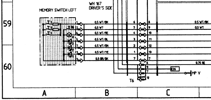
- The two resistors (240 Ω and 820 Ω) on the PCB are unrelated to any of the LEDs or incandescent bulbs. They are used to encode which of the memory position (1/2/3) switches are depressed. From the diagram (see below; upper resistor is the 820 Ω one, lower resistor is the 240 Ω one), the resistance of pin 1 to 4 of the connector will be: ∞ Ω if none of the memory position buttons is pressed, 0 Ω if "1" is pressed, 240 Ω if "2" is pressed, and 820 Ω if "3" is pressed. You can figure out what you'll get if various combinations are pressed. None of this matters for the LED conversions we're investigating.
Last edited by Ed Scherer; 06-26-2017 at 01:55 PM.
 06-25-2017, 01:56 PM
#17
Drifting
Thanks Ed, but after selecting the appropriate LEDs for the conversion, what did you deduce about how the LEDs behind the position buttons should operate? Mine simply backlight the buttons (fairly dimly as you say, but on a dark night with eyes adapted they would stand out adequately)
06-25-2017, 02:00 PM
#18
Addict
Rennlist Member
Rennlist Member
Thanks Ed, but after selecting the appropriate LEDs for the conversion, what did you deduce about how the LEDs behind the position buttons should operate? Mine simply backlight the buttons (fairly dimly as you say, but on a dark night with eyes adapted they would stand out adequately)
06-25-2017, 02:07 PM
#19
Addict
Rennlist Member
Rennlist Member
If anyone does want to dive deeper into disassembly of the seat/mirror memory switch/indicator assembly, I can offer some tips:
I've got lots of photos that go along with this, but have never uploaded them anywhere for sharing. I'd be happy to do that (no sooner than about 8 hours from now, though, probably) if there's any interest.
- Don't do it unless you're willing to spend an hour or two (minimum) on it. This assembly is not designed for easy disassembly.
- The black plastic part is held down by the 3 LEDs.
- The PCB is held to the assembly by the solder joints to the connector pins.
- Thus, to remove the PCB, you can either (a) twist off/break the 3 LEDs, remove the black plastic part, and then de-solder the connector pins, or (b) de-solder the connector pins (working around the black plastic, which isn't easy), in which case you'll still have the LEDs holding down the black plastic piece.
- Reassembling (if you've removed LEDs, replaced LEDs and/or incandescent bulb, etc.) order is: (a) place black plastic piece on PCB, solder LEDs to PCB, thus also fixing black plastic piece to PCB; (b) place PCB on connector pins and solder them (working around black plastic piece, which isn't easy, and you'll likely melt it here and there).
I've got lots of photos that go along with this, but have never uploaded them anywhere for sharing. I'd be happy to do that (no sooner than about 8 hours from now, though, probably) if there's any interest.
Last edited by Ed Scherer; 06-25-2017 at 02:31 PM.
06-25-2017, 03:23 PM
#20
Electron Wrangler
Lifetime Rennlist
Member
Lifetime Rennlist
Member
Inquiring minds and all...
Alan
06-25-2017, 04:00 PM
#21
Drifting
Just a wild guess - maybe until a position is memorised when system is new, the non-available positions are not lit?
In this connection, I wonder how long the car had to be without power for all memory positions to be cleared?
In this connection, I wonder how long the car had to be without power for all memory positions to be cleared?
06-25-2017, 05:39 PM
#22
Electron Wrangler
Lifetime Rennlist
Member
Lifetime Rennlist
Member
Alan
 06-26-2017, 01:43 PM
#24
Addict
Rennlist Member
Rennlist Member
If you want to replicate this upgrade with the exact parts I used, you'll need:
- (3) SuperBright LEDs RL3-W8080 (3 mm, cool white, 8000 mcd, 30� beam spread), for the 1/2/3 switch backlighting
- (1) SuperBright LEDs RL3-R4545 (3 mm, red, 4500 mcd, 45� beam angle), for the memory switch backlighting
- (1) 680 Ω, 1/4 W resistor (carbon film will suffice)
As you've probably already discovered, the memory seat/mirror switch/indicator assembly just pries out (use a plastic prying tool so as not to damage anything) and just unplugs. I don't have any photos of this.
You'll wind up with the following assembly, 928.613.245.00 (at least, that's what it is on my 1990 928 S4).

Using one or two small screwdrivers or other prying instruments, pry around the edges. I don't remember the details of this, but now that I look at the photos, it looks like there are catches along the short edges that need to be pushed outward to release.


Oh... did I warn you about the little springs on the switch plungers? Make sure you don't lose them when you pry things apart! You can see them in this photo:

You now have these two pieces:

You can easily remove the white plastic reflector for the incandescent bulb; it just lifts off. To remove the black plastic holder for the three yellow LEDs, you will either have to first desolder the seven connector pins (hard to do since you have to work in the very confined access areas in the black plastic LED holder) so you can get to the back of the PCB, or do as I did, and just destructively remove the yellow LEDs: with pliers, just twist and pull out each one).

Once the LEDs are removed, you can just lift off the black plastic piece.

This gives you much easier access to the solder joints for the seven connector pins. You can now desolder these (on the top side of the PCB). You'll need a solder sucker and/or solder wick. Upon completion, you'll have completely freed the PCB. I also had desoldered the incandescent bulb (from the bottom side of the PCB) and the stubs of the leads for the twisted-off LEDs (from the top side of the PCB) before taking this photo.

The top side and bottom side of the PCB, before further work. Now would be a good time to apply contact cleaner and/or DeoxIT to the switch contacts.


If you want to replace the incandescent bulb with a red LED, you'll need to add a current-limiting resistor. Compare the following photo of the top side of the PCB with the top side of the PCB a couple of photos back. You'll notice that close to the bottom lead of the left resistor, there are two new holes and the trace that curves around under that lead has been cut.

FWIW, I used a sharp tool to cut the trace and a drill press (gross overkill on choice of this tool, I know!) to drill the holes. Any number of alternatives would get the job done.

In the next photo, I've soldered in (from the bottom side of the PCB) the single red LED (note that the long lead for the anode is on top; this is important) and have inserted and trimmed the leads (but not yet soldered) the current-limiting resistor from the bottom side of the PCB.

Solder the current-limiting resistor to the PCB (from the top side of the PCB).
The other side of the PCB, showing the placement of the 680 Ω, 1/4 W resistor.

Insert the white LEDs in the black plastic holder (note that the anodes with the long leads are on the left; this is important) as shown, and then insert them into the PCB and solder them (from the bottom side of the PCB).


No photos of this, but place the PCB on/over the connector pins (i.e., make sure the soldering part of the connector pins are fully inserted through each corresponding hole in the PCB). Solder each pin to the PCB (from the top side, the only side accessible now!). This is a bit tricky, as you're working with the tip of the soldering iron very close to the black plastic piece (for two of the pins, the tip will be entirely surrounded by plastic!). You will likely melt the plastic a bit here and there. It probably won't matter unless you're really sloppy. You'll see that I melted a bit, but it doesn't effect functionality and is entirely hidden upon reassembly.
Put the white reflector back where it belongs.

Make sure all five springs are still present on the switch plungers, then snap the two pieces of the memory seat/mirror switch/indicator assembly back together, and finally, reinstall in the car (no photos).
Appreciate the improved lighting!

Last edited by Ed Scherer; 06-26-2017 at 02:29 PM.