

Temp II testing and results?
 11-08-2003, 12:09 PM
#1
Advanced
Thread Starter

Join Date: Oct 2003
Location: RTP, NC
Posts: 93
Likes: 0
Received 0 Likes
on
0 Posts
Based on my mechanic's suggestion and some reading of archives here I decided to test the Temp II sensor. From what I gathered this sensor is the one under the crossbar with the blue plug. After removing the "Oh Jesus" clip I hooked up my ohm meter and started the engine. I tested each pin to ground. Each pin gave me a zero reading, like the meter wasn't even hooked up. I got the same reading as the engine warmed up before eventually stalling.
Just to make sure it wasnt a faulty meter I measured the resistance between the two pins and it was a constant 3800 Ohms.
With these results doesnt that sound like a bad sensor, or should I get some results no matter how far out of tolerance? What I read said take a reading from each pin to ground and although hoding the meter needle to the pin took some fanagling, I should have made contact at least some point in wiggling the meter needle.
The car is cooling down now so I'll take the reading again this afternoon.
Thanks
- Eric
 11-08-2003, 12:50 PM
#4
Racer
Join Date: Jun 2003
Location: McDonough, Ga.
Posts: 369
Likes: 0
Received 0 Likes
on
0 Posts
If I remember correctly the sensor has three pins. Basically two sensors in one housing. The test points should be from one outside pin to the center then the other outside pin to the center. Try that and see what you get.
11-08-2003, 01:17 PM
#5
Rennlist Member
Join Date: Mar 2003
Location: Nashua, NH
Posts: 4,328
Likes: 0
Received 0 Likes
on
0 Posts
Hey Ed,
The sensor has two pins, each of which makes a separate circuit to ground.
Eric,
It's unlikely that both legs have shorted to ground, so I suspect some problem with your hook-up.
One simple way to test the sensor is to remove it from the car (24mm I think) and to test each leg of the sensor as you're heating it in a pot of water. You should be able to get a small aligator clip to grab each leg.
11-08-2003, 01:23 PM
#6
Advanced
Thread Starter
Join Date: Oct 2003
Location: RTP, NC
Posts: 93
Likes: 0
Received 0 Likes
on
0 Posts
Ed I triple checked and checked again for good measure that there are only two pins. Maybe being a Euro with CIS?
Ernest I'll give your idea a try. It is a bugger to get direct access to those pins while it is installed.
Findings to be posted soon. (I hope)
Thanks
Eric
Ernest I'll give your idea a try. It is a bugger to get direct access to those pins while it is installed.
Findings to be posted soon. (I hope)
Thanks
Eric
Trending Topics
11-08-2003, 02:08 PM
#8
Advanced
Thread Starter
Join Date: Oct 2003
Location: RTP, NC
Posts: 93
Likes: 0
Received 0 Likes
on
0 Posts
Hey Ernest. The whole time I have been testing a sensor that has a blue palstic housing and with a blue connector. This one is held in place by a couple of hex bolts and has a fule line connected to the end of it. It is in front of the two blade sensor that I believe is for the temp gauge, and its on the passengers side of the engine , right below the hoses that come out of the oil filler housing.
I couldn't figure out what you meant by using a 24 mm wrench until I noticed another sensor lower in the engine compartment that is almost in the middle of the two large radiator hoses. The sensor housing is blue and accepts a 24 mm wrench, and the wire connector is brown.
Could this be the temp II sensor and not the other one. This first sensor I am trying to remove has the hex bolt above and below it. Getting the top bolt out is easy. I haven't even been able to crack the bottom one.
Thanks
Eric
11-08-2003, 03:12 PM
#11
AutoX

Join Date: Nov 2003
Location: Hartford, CT
Posts: 11
Likes: 0
Received 0 Likes
on
0 Posts
Eric - I'm no expert, but I am checking my temperature sensor also. According to the manual the brown plug is the temperature time switch. I think I remember seeing somewhere in the manual that the blue is the cold start valve. The temp II sensor is grey.
I don't think the '81s had a Temp II sensor. The fuel injection wiring diagram shows a single temperature sensor, with a yellow wire connecting the sensor to the control unit, and a brown wire to ground.
I think the manual page is 24-17. I'm new to 928s, but I think that is correct?!
Good Luck!
Bob.
11-08-2003, 03:30 PM
#12
Advanced
Thread Starter
Join Date: Oct 2003
Location: RTP, NC
Posts: 93
Likes: 0
Received 0 Likes
on
0 Posts
Bob, Hah I saw your post about troubleshooting your temp sensor too. Good luck. I guess today is the day for it.
I'm learning as I go as well but my understanding is that the 81 US cars were L -jetronic injection while the Euro model was K-injection (CIS). Perhaps that is the difference with the wiring? The cold start valve (as identified by my mechanic) is on the rear passenger side of the engine toward the back of the engine. It has a brown plug on it. Mine is currently disconnected as I havent got around to replacing it yet.
Somebody should be able to identify the pictures we have posted. Based on some of the other wiring jobs that a PO did, I'm not quite ready to trust identifying parts only on wiring color.
Good luck with your troubleshooting as well
- Eric
11-08-2003, 03:40 PM
#13
Inventor
Rennlist Member
Rennlist Member
Uh, aren't the '81 Euro's K-Jet (CIS)? The cold start injector on the front of the plenum is a dead giveaway. No Temp II sensor.
I'm no K-Jet guy but isn't the WUR the problem here?

If it is somehow an L-Jet then the Temp II is number 6, 8 is the gauge sensor and light, and 10 is the cold start thermo-switch.
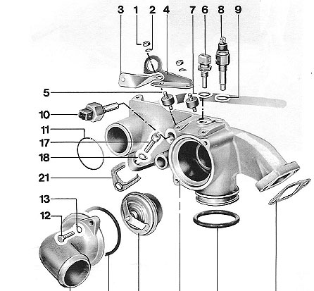
BTW Temp I is the air temp sensor on L-Jets.
I'm no K-Jet guy but isn't the WUR the problem here?
If it is somehow an L-Jet then the Temp II is number 6, 8 is the gauge sensor and light, and 10 is the cold start thermo-switch.
BTW Temp I is the air temp sensor on L-Jets.
11-08-2003, 04:36 PM
#14
Advanced
Thread Starter
Join Date: Oct 2003
Location: RTP, NC
Posts: 93
Likes: 0
Received 0 Likes
on
0 Posts
Hey Bob I looked at the manual again and where it shows the Temp II sensor theres not one on mine. Go figure I guess it doesn't have one. So that answers the question of what the second picture is - The temperature time switch. Agghh frustrating, frustrating - thanks though for bringing that up.
PorKen - Thanks for the diagram. My mechanic identified what I called in a previous post a Cold start valve a cold start solenoid (I found my notes) this device has a white plug on it not brown as I incorrectly stated in a previous post. When I bought the car it was disconnected and when I connected it back up the car would not restart when hot.
I tested fuel pressure a few weeks ago and it was fine at hot and cold temps. I guess I am back to the WUR again. I did notice on the WUR earlier while I was looking at the temp time switch a vacuum line nipple on the near bottom. There was only enough line covering the nipple so perhaps that missing connection is the key. The spark system appears fine in all aspects, and with the cold weather here the problem is something that changes as the car warms up (I know, back to the WUR)
I'll talk to my mechanic again, he is highly respected in this area on 928s and perhaps there was just some miscommunication.
Thanks
Eric
11-08-2003, 05:46 PM
#15
Advanced
Thread Starter
Join Date: Oct 2003
Location: RTP, NC
Posts: 93
Likes: 0
Received 0 Likes
on
0 Posts
Using the shop manuals this time the WUR has two vacuum hoses that go to each side of the throttle body. The hose on top of the WUR in connected, the bottom one missing. Going back to the throttle body I found the nipple. It had a two inch piece of hose that had been sealed off at the end. Weird. The diameter on this hose is larger then what is on the WUR but I am guessing it just needs the little plastic hose connector between them? I'll be replacing that tommorrow so I'm *hoping* that is the problem.
Eric
Eric