When you click on links to various merchants on this site and make a purchase, this can result in this site earning a commission. Affiliate programs and affiliations include, but are not limited to, the eBay Partner Network.
I just got back from some travel a couple of days ago and will be traveling more during the second half of this month, so I probably won't be able to make any more progress on this until early July.
I still have every intention of working on this and got the necessary materials last week, but just haven't had any time to work on it.
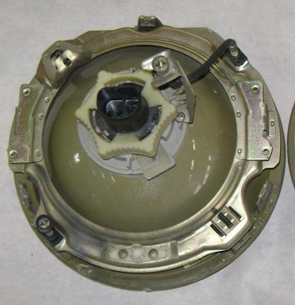
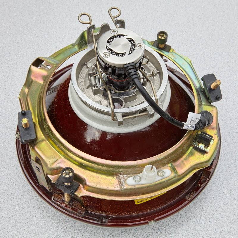
The rear cover is very different between the H5 and H4. See below:
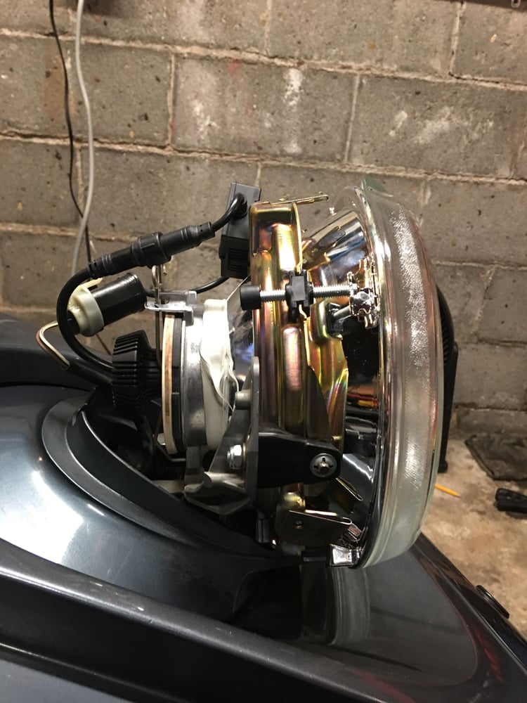
Rear of the H5 lens. No cap.
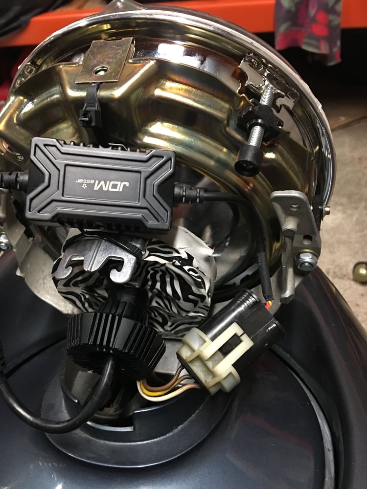
Rear of the H4 lens. The cap is missing, but the large silver retaining clip around the LED bulb holds it down.
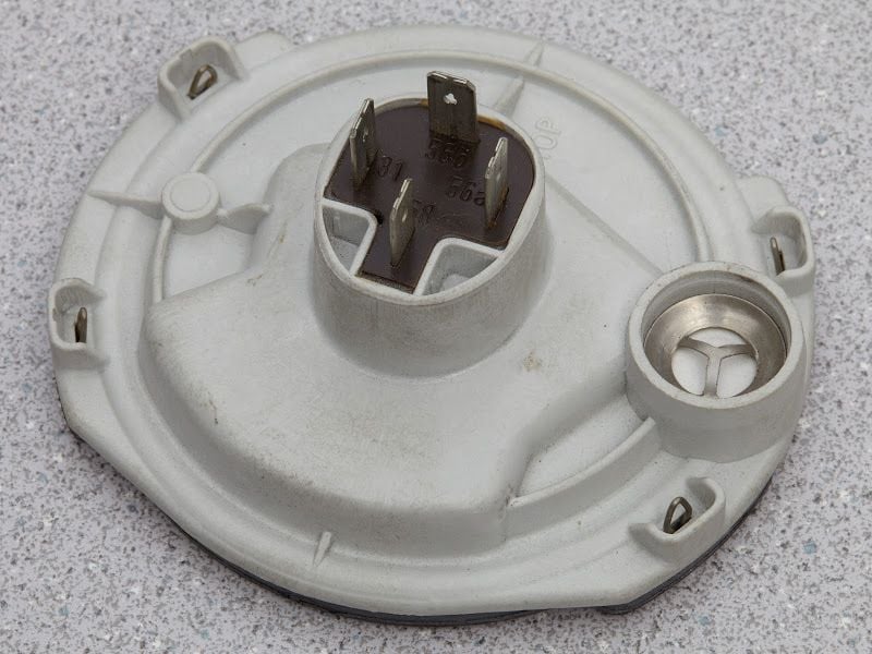
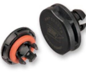
Here is the cover we are going to replicate, without the H4 connector. It will have a hole to accommodate the threaded portion of the Philips H4 LED bulb.
I will have to check if I have one laying around. If someone wants to send one, I would model it for a round of beers at our next local 928 get together.
I don't really see much value in modeling the original H4 caps; there's really no reason to preserve the exact shape. I've already taken measurements of all the critical dimensions that are involved in all the sealing and fastening surfaces.
Thanks for the offer, though, and I'd be happy to buy a round next time we're at the same gathering, anyway.
I really only see benefit in modeling the overall height of the cap (so the clips will still have adequate compression on the cap), the wall thickness (so the cap doesn't deform when clamped down), and outer profile and sealing surface. A gasket can easily be made with a rubber sheet from McMaster Carr, or RTV if a channel is used instead of a flat mating surface.
I really only see benefit in modeling the overall height of the cap (so the clips will still have adequate compression on the cap), the wall thickness (so the cap doesn't deform when clamped down), and outer profile and sealing surface. A gasket can easily be made with a rubber sheet from McMaster Carr, or RTV if a channel is used instead of a flat mating surface.
I'd suggest using standard o-rings for the sealing both around the LED bulb stem and for the cap to reflector ring seal. No reason to preserve the original style seal - I'd suggest creating a grove for both o-rings in the body one interior for the bulb stem and one exterior sealing to the inner surface of the reflector ring (not the face) - this way the o-ring can be mounted in a very secure groove. The tolerancing will be more challenging initially (may require a few 3D print iterations) but it will make for a very nice seal when perfected. The cap can be made smaller this way also.
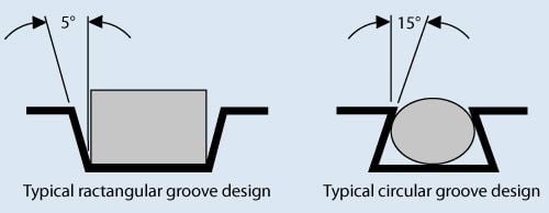
An O Ring is a perfectly acceptable solution. When modeling, don't forget to have the correct angles in the groove profile to hold the ring and seal correctly.
I was gone for a couple of weeks and then busy with other stuff, but I've had a chance to spend a little time on this project over the last few days. I've got almost everything I need to crank out a few prototypes (probably will initially make 5 pairs). I'm about 75% done with a design that includes a workholding fixture that will allow 5 pairs of caps to be cut from a 12" � 24" � 3/8" plastic sheet (my initial prototypes will use ABS; I might switch to a different material later).
One detail that I decided to look into a little more thoroughly is venting. This is a topic that I really had no knowledge about or experience with. After looking into it more, I'm fairly convinced that it's important to do proper protective venting. I discovered that this appears to be a standard problem with standard solutions (no surprise, but again, just a big learning curve for me). For this application, I think having a proper vent in each cap will be desirable for two reasons: (1) to prevent pressure / vacuum from causing problems with the seals, and (2) to assure that air that passes through any venting solution doesn't allow moisture and contaminants to enter the headlamp cavity.
An interesting video that demonstrates the problem:
The vents come in three styles worth consideration: screw-in, snap-in (a.k.a. snap-fit), and adhesive. They're all based on some kind of a membrane (typically a hydrophobic and/or oleophobic material such as ePTFE), and, in the case of the screw-in and snap-in versions, enclosed in a plastic (or even metal) case.
I'd prefer to use snap-in vents (easiest to work with, no tapping or nut required, etc.). I'd prefer to go with Gore (or maybe Donaldson) if possible; their websites and readily-available technical information is way better than Milvent's.
The problem is that these vents don't appear to be available in small quantities through the channels (Digi-Key, McMaster, MSC, etc.) where I expected to find them. Too specialized, I guess.
Milvent does appear to sell on Alibaba, but I'm not sure I want to go that route. There's one seller on eBay selling some of the Gore screw-in vents. Pricey, though.
So, before I put any more energy into this, do any of you have any experience in this area, both technical and/or sourcing these vents? Anybody have an existing relationship with one of these companies such that you could score some "samples"?
Just so I can keep rolling, I might go ahead and get a few of the available Gore screw-in vents off eBay, but I'm not too thrilled about dropping $6 each for them.
Last edited by Ed Scherer; 07-13-2016 at 08:29 PM.
Well, I finally found some sources (both short-term reduced price liquidator, but also reliable permanent channels) and alternate part number for the membrane vents. Looks like Gore PMF100320 is also rebranded as Bopla 52042000. Interestingly enough, the packaging under the Bopla brand is in German. Seems appropriate.
And I can also inform you that this remarkable little part in German is known as a Druckausgleichselement.
Since this project was mentioned in another post today, I thought I'd give a little status update.
I actually worked on this a few weeks ago. Got the workholding fixture done, got some material that I thought would work (12 in. by 24 in. sheet of 3/8 in. ABS). Ran into trouble pretty quickly just drilling holes in it; the damn stuff melts really easily. I haven't worked with ABS sheets before, so I need to work on speeds and feeds. I think I'm having more problems with simple holes (relatively long period of time with drill mill in holes) than I'll have with pocket and profile cuts (single flute spiral O bit designed for soft plastics). It's kind of frustrating working with new materials. At one extreme, you melt or burn the material. At the other extreme, you can break the cutters, which, at about $30 a pop, gets expensive really quickly.
On a positive note, the membrane vents I got should work just great.
I'm hoping to get back to this over the next couple of weeks.
I might use this as an excuse to get a vortex tube for air blasting/cooling on my ShopBot, but I'm not sure I really need another thing to mess with right now.
Great progress, Ed! We just replaced our printer at work with a much higher resolution model for a better surface finish. If it's possible to get a CAD file from a 3D scan, I can assist with printing a set and ship them to you for free.
Motivated by the desire to finally get this replacement cap project off the ShopBot (it's been on there for ages!) so I can use the ShopBot for another project, I finally made some serious progress over the weekend.
Photos the first prototype are below. Haven't tried it on the car yet and I'm guessing it will require a few tweaks, but I'm pretty happy with how it's looking so far.
The first prototype has a few minor flaws (I had some problems with the ABS melting when I drilled the first holes and the melted ABS strings created some ugly concentric circles around the holes; the holes also had some melted ABS inside, which is why you can see some evidence of hand-reaming). I've already solved that problem, but decided to use these anyway, since this is probably a throw-away prototype. The O-ring slot in the bulb barrel hold isn't quite where wanted it, either. And it's a little too tight; I probably need to make the slot slightly deeper and/or use a slightly larger O-ring (no problem; I've already got slightly larger O-rings but haven't tried them yet).
First, I've set things up so I can make ten at a time, although right now, I'm just doing a single prototype.
The front side, along with the O-ring and breather vent. A few things to note:
There's a slot in the hole for the LED lamp barrel to hold the O-ring.
There's a threaded hole (with the proper-depth 60� chamfer recommended by the vent manufacturer) for a screw-in (M12�1.5) membrane vent.
There's a pocket for an LED driver, along with some slots that can be used for nylon wire ties to hold the driver down (additional two-sided tape would probably be a good idea, too).
The four small round holes are there primarily for holding the cap during machining.
The back side, along with the seal that will be used.
Assembled, front and back.
The LED bulbs and driver I mentioned in post #15 inserted/mounted for test fitting.
Last edited by Ed Scherer; 05-02-2017 at 03:39 AM.
That is excellent work. A big improvement over my wood prototypes. I like the fact you used aluminum to aid with the heat sink effect and added a vapor port. Plus the addition of a mounting tab for the power supply was a very nice touch and will make mounting very convenient.
Any plans to sell? I'd be interested. PM me if so.
BTW, I have been watching the lumens increase for these specific models. When I purchased mine, they lumens were 3500 lumens (about 65% increase over stock) but now I am seeing the same design with outputs of 4000 and even 6000 each. I think the 3500 are more than adequate and I haven't been given the 'too bright" flash by oncoming traffic.
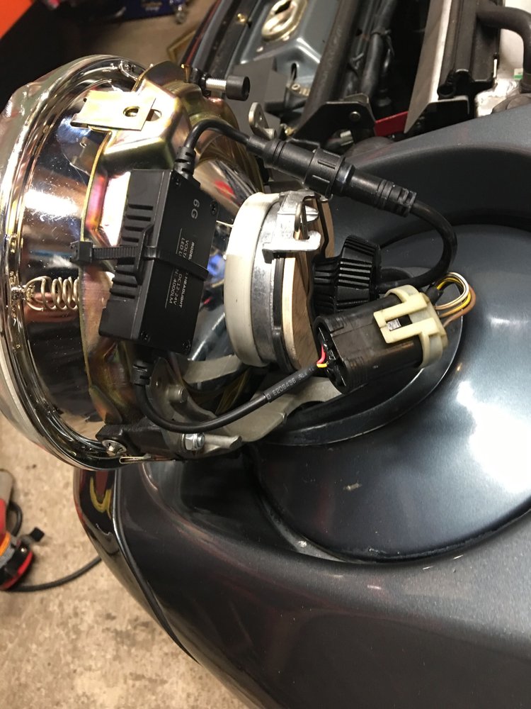
For reference here was my installation, as you can see the mounting of the power supply was a bit jenky

 06-14-2016, 11:55 AM