When you click on links to various merchants on this site and make a purchase, this can result in this site earning a commission. Affiliate programs and affiliations include, but are not limited to, the eBay Partner Network.
I couldn't tell you... I just bought 16" ground cables that matched the stock length for my S4. You'll have to research the length difference.
Could you measure one from the bolt hole that attaches to the chassis to the center of the post mount hole and let me know the specific measurement? Thanks.
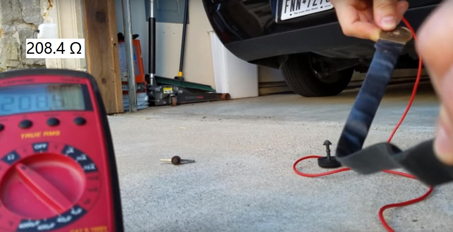
Alright folks, stage 1 of replacing the voltage circuit done (well, maybe the alternator was stage 1?) Anyways... I took a video showing the variance in resistance that the original ground strap had. It ranged from 0.4 - 208.4 ohms... yes, you read that correctly. Granted, I could only get that for a fraction of a second, and could almost consider it an anomaly, but there were other 'blips' of over 100 ohms as I moved the strap around... so it's reasonable to assume that while driving the strap would see some resistance spikes that could definitely mess with the electronics of the car over time.
In shorter words... CHECK YOUR STRAP!!
Still have the positive cable, engine ground strap, and engine harness to replace, sitting in the garage.
The video I took covers the original battery strap resistance, my replacement strap I built (Waytek 16" 2 gauge strap and sealing heat-shrink tubing), and then I open up the old strap and show the corrosion at the connector.
So far I've updated the following components: Battery ground strap, engine ground strap, new alternator, engine wiring harness, positive cable from battery to starter. I've also direct-powered my headlights to reduce that load on the alternator. These parts were all older than 5 years (with a majority being original 1987 parts), so the peace of mind that they are new is a great feeling.
I still get a voltage drop at stop lights (settles at around 12.2V (Thanks for the correction Sean) measured at the jump post, 10.6V measured at the 12v outlet in the car), but the alternator is providing ample current to keep the battery charged, so that's good. There's nothing left in the wiring system for me to replace, so I'm going to start checking fuses for current draw of different circuits.
Last edited by traxtar928; 08-31-2016 at 11:54 AM.
I'm just betting that underneath the pretty red tape job in the first picture of this thread is a green colored copper remainder of what was once a main power cable from the alternator.
I'm just betting that underneath the pretty red tape job in the first picture of this thread is a green colored copper remainder of what was once a main power cable from the alternator.
I have replaced every component of the charging system on this car... Optima Red Top, Waytek battery ground strap (I have an extra for sale), 0AWG marine cable from battery to starter, Sean's engine harness, Engine ground strap, and Bosch alternator.
I have a feeling that something in the HVAC system is pulling down the voltage when the car idles (maybe the compressor??), since the drop doesn't happen when I turn everything off at the HVAC controller. If I turn off the A/C when the voltage is at its lowest, it will slowly start to rise again.
The drain on the compressor is a few amps most, used to energize the clutch coil. The fans come on with the AC, but the supply for those comes directly from the battery positive terminal.
Seems like you still have a significant voltage drop between the jump post and the 30 bus on the CE panel, or wherever you happen to be measuring voltage inside the car. The connecting wires between the jump post and the 30 bus on the CE panel are, in my opinion, way undersized. You can measure the actual voltage drop in that cable by placing one meter lead on the jump post and the other at the CE panel, with meter reading DC volts. The meter should read actual voltage lost directly. A valid measurement needs to happen while driving and with full electrical load on the 30 bus in the CE panel.
Folks seem to like to put updated audio equipment in the car, powered from the CE panel rather than from the alternator and battery. We install higher-wattage headlights and foglights. Whatever you add to the CE panel, it draws that current through the wire sections between the CE panel and the jump post, the wire section between the alternator and the jump post. If the alternator isn't supplying sufficient voltage/current, the section between the starter and the alternator, and the section between the battery and the starter are added to the "potential problems" (sorry, I couldn't resist...) list. In parallel (damn, did it again!), loads supplied directly from the battery positive terminal block include the fans (on S4+ cars), the fuel pump, the ignition and fuel injection. These are all high-current users, with a running flow path from alternator to the starter end of the battery cable, plus the positive battery cable itself.
You've replaced the starter-to-alternator and alternator-to-jump-post cables with Sean's replacement, so the next step seems to be the Missing Link wires between the jump post and the CE panel 30 bus. Test voltage drop in just that section as described above. The conductors between the jump post and CE panel legitimately need to be the same total cross-section as the alternator-to-jump post in your new engine harness, in my opinion.
Well I don't have any aftermarket equipment on the car besides a subwoofer which is directly wired to battery. The strange thing is that the voltage drop is definitely HVAC related... when I turn the system off no drop occurs and it stays steady (measured at the outlet) at 13.1 volts. Measured at the post, it's 13.5 volts.
Keep in mind this is also while the car is in drive (load on the engine), but putting it in park or neutral doesn't change the fact that the voltage drops.
I'll measure voltage loss between the jump post and the CE panel soon and report results. Probably within the next week or so.
You can certainly isolate the HVAC power users easily to isolate the power pig. Compressor is easily isolated by lifting one of the wires on the freeze switch under the cowl cover. The cabin fan passes power through the resistor block on any speed but high, so unplugging that (right above the freeze switch) should tell you about the drain from the fan motor.
The main cooling fans are powered through fuses 28 & 29 IIRC. Or, just unplug the final-stages module on the front apron, after loosening the little screw and moving the hold-down arm off the connector.
----
The two (IIRC) little wires that connect the jump post to the CE panel are subject to the same physical/chemical/age abuse that the FOE harness receives. The test for voltage drop through those wires (between CE 30 bus and the jump post) will tell you a lot.
Harbor Freight sells a little plug-in current tester, equipped with fuse terminals. The higher-capacity version fits in our CE panel fuse holders nicely. Pull the fuse from the suspect circuit, place it in the holder in the tester, plug the tester into the fuse socket, read the current passing through. One of these should probably live in the average 928 DIYer's electrical troubleshooting toolbox. It lets you conveniently measure DC current flow up to thirty amps, well beyond the typical (3 - 10 Amp) capacity of most multimeters.


 06-09-2016, 06:19 PM