When you click on links to various merchants on this site and make a purchase, this can result in this site earning a commission. Affiliate programs and affiliations include, but are not limited to, the eBay Partner Network.
"... I think I found the 194 LED's still didn't disperse the light properly...."
Don't know what 194's you tried but here is pic using only one (on the left) of the ones I posted the link to.
You can see the difference compared to the stock bulb on the right, can you imagine what three would do, IMO may need only two, one on each side none in the middle.
Don't know what 194's you tried but here is pic using only one (on the left) of the ones I posted the link to.
You can see the difference compared to the stock bulb on the right, can you imagine what three would do, IMO may need only two, one on each side none in the middle.
Do the triangle reflectors still have some mirror shine on them? As I remember but technology has changed I couldn't get the light to be much better without a good reflector. Yours looked like they work. I can see the difference between the left & right lights.
As far as the mirror like reflector backing I can't say as I didn't remove the Pod(s) I have them installed in 3 cars now and just did a 91 and an 88 S4 for a friends using the same LED's all look the same.
The newer multi-SM LED's are a big improvement over the older type single LED design, I've also had a much improved results using a similar SM-multi LED for the HVAC, however adding reflector material would improve that application IMO.
I too have the Garage9 (90buck) LED update in my Blue 85, had 2 fail, next time they go out I'm going back to Stock and using these newer multi-SMD's.
Option 2: Reverse engineer the Jager LED's and replace them with white. The LED's used are component LED's and need to be able to handle at least 15volts. The LED's are 5mm diameter and have no shoulder. I haven't really looked hard but didn't see any on superbirhgt or my local electronics store. Most are far lower volt ratings.
Current-limiting resistor math for discrete LEDs is quite simple; see the section "Choosing Current-Limiting Resistors for Discrete LEDs" in Converting Porsche 928 Interior Lighting to LEDs for a simple, conservative approach to finding an appropriate resistor value; it ignores the voltage drop across the LED spec (thus giving a more conservative result); it's the maximum forward current you need to pay most attention to. For example, the Radio Shack LEDs shown a few posts back show a maximum voltage drop (which will also be maximum allowable current) of 20 mA. Let's use 14 V as the power supply (it's usually > 12 V, but < 14 V).
14 V / 0.02 A = 700 Ω
To be more accurate (as is the on-line LED calculator), you should actually account for the voltage drop across the LED, thus:
(14 V - 3.6 V) / 0.02 A = 520 Ω.
Regardless, I'd go with an 820 Ω resistor (or larger). Lower current through the LED means longer life.
Power dissipation for that will be no more than (14 V)^2 / 820 Ω = 0.239 W, so an 820 Ω, � W resistor will suffice. If you go smaller than 820 Ω, you should probably go with a � W resistor. Especially if it's enclosed in heat-shrink tubing and thus can't dissipate heat as effectively.
Step up to larger value resistors if the LED is too bright.
Last edited by Ed Scherer; 12-16-2016 at 10:10 PM.
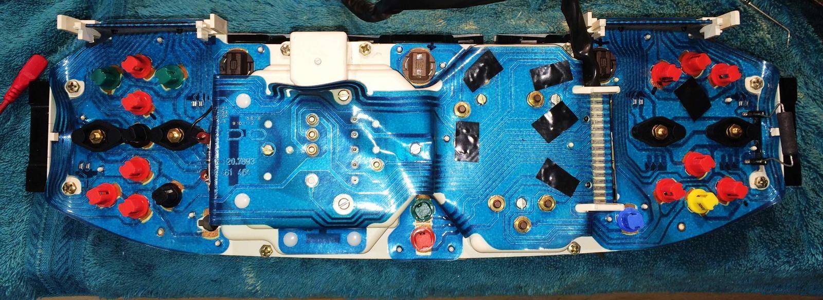
I'm a bit slower than others on here, but just for photo options, here is the back of my cluster with bulb negatives marked with the black marker.
I was inspired by your photos of led upgrade to attempt the same in my car.
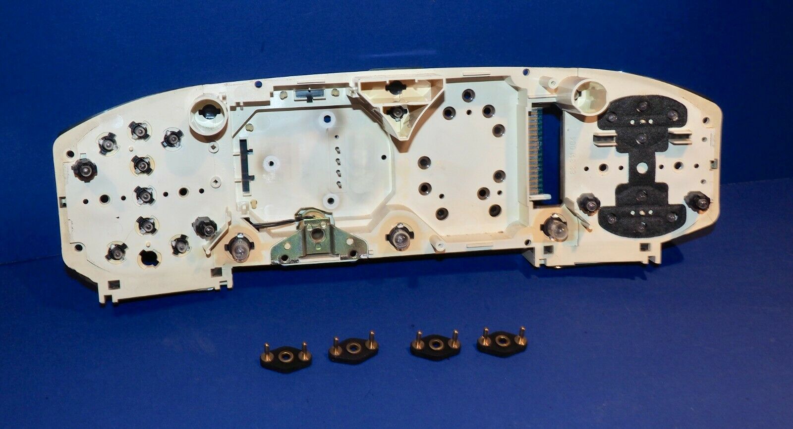
Is there any way to tell which side of the bulb is negative before placing it in the socket in the position described in your pictures. I have bought a replacement cluster housing and circuit board which I was hoping to fit with the new superbright leds on my desk before taking out the old cluster and swapping over the gauges to my new one ? How can I tell if they are in the right way without trying them out when connected in the car.
I was inspired by your photos of led upgrade to attempt the same in my car.
Is there any way to tell which side of the bulb is negative before placing it in the socket in the position described in your pictures. I have bought a replacement cluster housing and circuit board which I was hoping to fit with the new superbright leds on my desk before taking out the old cluster and swapping over the gauges to my new one ? How can I tell if they are in the right way without trying them out when connected in the car.
You can also install the bulbs and hook your 12v source to the back of the circuit board before you install the pod back in the car. It's been quite a while since i did the 79 and the GTS, but someone may chime in on this. Took my 12v source and alligator clipped them onto the board. You've got a 50/50 shot at installing correctly, then just pull and reinstall the rest. I did NOT do my iddiot lights in LED as they rarely go off (theoretically)... Good luck w it, it's a great project!!
Thanks for that, but where on the circuit board do you place the alligator clips. I dont know anything really about auto electrics. Perhaps you could mark on a pic of the board.
Last edited by murray928; 06-29-2021 at 11:51 AM.
Reason: Needed pic of board
I think Ed has it on his thread. (Led upgrade)
Worst case, set the gauge cluster on the Column and temporarily connect the pod harnesses. Turning ignition key should activate illumination and check if that way. You�ll see pretty quick which light up and which don�t.
Many thanks for the advice. Double checked polarities with a 9v battery and a multi meter. I know now how to do one thing with that multi meter.
Will post a picture when I have it installed.

 12-15-2016, 04:54 PM