When you click on links to various merchants on this site and make a purchase, this can result in this site earning a commission. Affiliate programs and affiliations include, but are not limited to, the eBay Partner Network.
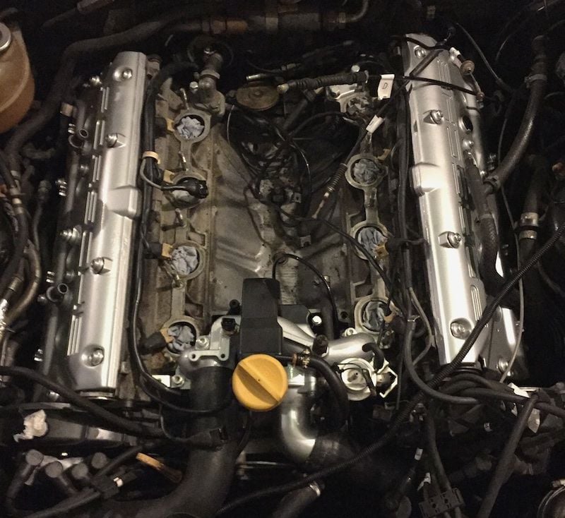
Here is a pic from Dwayne's intake refresh on his '87. It does show one port plugged. The other line runs to the air pump diverted valve. Since I eliminated my air pump I will just plug this also.
It says that the left port is a vacuum test line and should be capped (with red rubber cap).
The right one goes to the air diverter valve. If you remove the air pump and all that goes with it, just cap that port too. Don't forget to cap the pipe to the catalytic converter.
FWIW I would suggest the test fit the manifold onto the heads without the gasket,
and use a feeler gauge to find the areas with the most clearance this will require the removal of the lower section so you can work the middle of the manifold Dont crimp that port plug it with a rubber cap.
A direct check of flatness sounds like a wise precaution. How much gap is tolerable?
I am currently pondering the flappy stop, which was missing, and probably contributed to my stuck flappy. According to Dwayne, I need to fabricate something, a disk with a hole in it, e.g., a cut-off bolt head. I've just sent a note to Roger....
Nothing to report that's particularly exciting. I have been slowly working away on a few details.
I checked for flatness as Stan suggested - very flat. It also reminded me to make sure the intake and water bridge won't interfere as I bolt them on later (another valuable tip from the birthday boy).
Roger does not carry a flappy stop nut, so I've penciled up the critical dimensions so I can make one. I'll scrounge about in junk jars for the raw material.
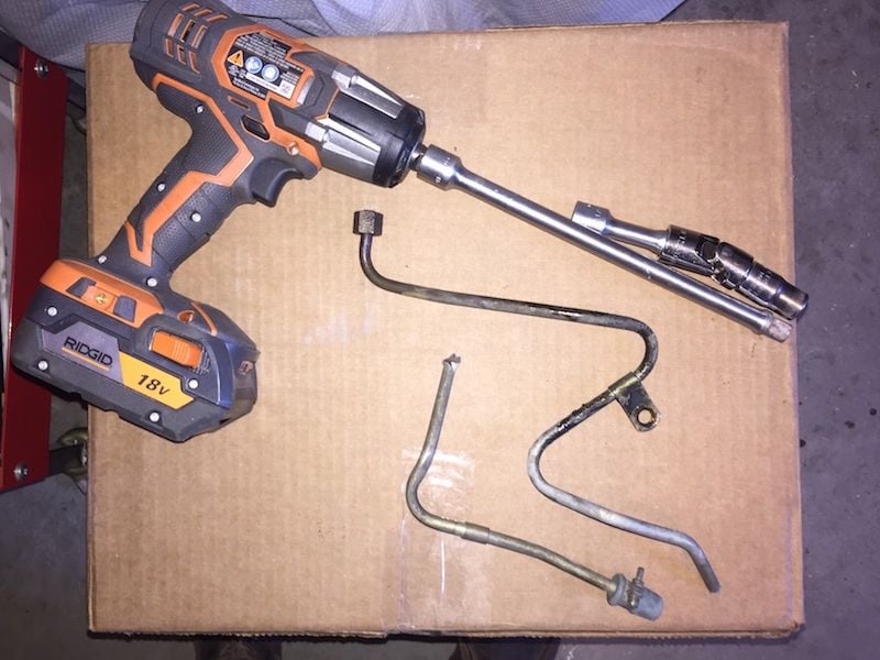
I removed the sampling tubes and the air pump tube. That should make reinstalling the valve covers a lot easier. I've been dreading this job, but the right tools helped.
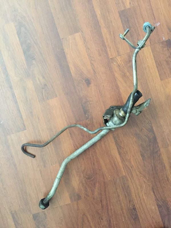
Some signs of anger may be seen. The other tube had broken, apparently from pushing it around as I removed a valve cover.
1/4" ball bearings were just right to plug the sample ports; there's a very good hardware store in the area with a zillion cabinets of screws, nuts and miscellaneous items.
To close off the air pump tube down by the catalysts, I first had to cut the tube to get the fitting. Then I ground down a nickel just enough to fit inside, and screwed it on tight. A California buyer will just have to weld the tube back together (and remember to put the fitting back first!)
It's nice to have a slightly less-stuffed engine compartment.
Yesterday's project was the Hall sensor. Such a simple thing. After all the work I've done without damaging anything, I approached it with confidence. And was immediately punished by rounding over a bolt head. I was more careful with the other bolt, after threatening it with a torch.
If you give me a few hours to ponder a problem, I can come up with a good solution. The bolt is in a tight spot, of course, but it was possible to put a big vice-grip on the head, with the vice-grip pointing away. Not good purchase - the jaws have ridges going the wrong way for this. So I Dremell'ed a sharp notch in each jaw running the right way. This dug into the head really well. With the help of a big crescent wrench on the vice-grips, success! But I'm short one bolt.
The aforementioned hardware store is 30 miles away. I couldn't possibly have a metric bolt of that exact size in any of my junk jars, could I? Think.... Ah! How about the tool box I keep just for bicycles? Found one right away - the exact size, and not wimpy - an 8.8.
The jack for the old hall sensor was messed up, just like the knock sensors, etc. A bit awkward to clean out of the plug. Got the new bolt in finally. Then dropped the other one! Didn't make it to the floor, either. Back to the bike box - Yes! A second one.
I am a few days behind you in this job. Still haven't decided on powder coating the intake and covers, or just paint them.
What is the flappy stop?
John
The rolled pin that stops the valve at its fully open point is also supposed to have a nut on it to keep it from fully closing. You'll see discussion about this in Dwayne's re-assembly procedure. His was missing. Mine was missing; my flappy was stuck closed as a result of this, and timid driving by my PO.
Since there was no nut lying in the valley, I'm inclined to think it never had a stop.
I'm going to make one. The idea is that it should have a hole a little smaller than the rolled pin. Make the thing a little eccentric so I can adjust it. Perhaps some red loctite so it doesn't walk away.
Made from a 17mm bolt head, with a 0.250-inch hole slightly off-center. Removable with back and forth twisting (I pounded it on too far, and it interfered with the "open" stop arm). I pushed it in a little further after taking this photo, and added a little red Loctite for good luck.
It holds the valve about 1mm from fully closing. As I look at it now, I wish I'd ground the contact point to make it ... less pointy.
The covers went on fairly easily since I removed the sampling tubes and the air pump business. Doing a trial fit as Dwayne suggests is a good idea. I put gasket goo into the corners, but not elsewhere. The starboard cover went in smoothly and made a pleasant thump when it was home. For the port cover, I thought I should look underneath with about an inch to go - holy crap, the seal was dislodged from one end! I put some goo on the ends and tried again.
Is the starboard cover gasket OK? I can see it's good along the top and bottom, but there's no eye-balling the ends. I'm going to judge it OK by virtue of that nice "thump" sound, and that it set right down without any resistance. Recall that Dwayne needed a do-over on his....
All other adventurers should look before setting it all the way down, or use goo, or both.
The fancy cam cover bolts are set up to bottom out, at which point they impose a certain squeeze on the rubber washers and gasket, in series. I like that - a displacement-controlled procedure.. Since Roger sent me a full set of washers that normally go only on the lower bolts to increase the squeeze, I took the hint and used them on all bolts.
I think the silver cam cover bolts and washers are lovely. I even forgive the stubborn ones down low. Cleaned the oil cap, too.
Since the photo was taken, I've put the spark plugs back in. The tangle of loose wires is less frightening now. Remaining connections are becoming more obvious. The trouble in sending parts out for coating and replating is that I have only vague recollections of the disassembly.
After studying Dwayne's photo of the hose that connects to the forward oil filler neck port, I installed the wrong hose, the hose that should have gone to the cowl earlier - I guess I missed that. It almost fit, which confused me for a time. I wish I had a better sense of just how much to tighten hose clamps. As it is, I think it's mostly a matter of preventing the hose from popping off the nipple; for a vacuum hose, that's unlikely - in normal operation. Too much, and you risk a variety of ills.
For my next trick, I will set the intake down on stands, magically connect the under-intake connections, and hoo boy, it will seem like I've made real progress.
I've been dreading this ever since wrestling the intake off, but it was very little trouble. But the next owner needs to replace the throttle cable clip thing - it came off very hard, and went back on very hard.
Instead of cardboard or styrene supports, I had two pieces of scrap "one-by" pine board handy that fit just outside the studs. 3/4-inch thick, about 2 inches tall. It was a bit tight sliding them out, but otherwise I thought they worked well.
A catastrophe narrowly avoided: I loosened the rear knock sensor to better orient the cable, and very nearly forgot to tighten it back down.
Tomorrow, the injectors. I've read all about clipping them to the rails first. Still, I think I'll push it out of the garage before start up, and have some halon ready.
Curt, did I read a few pages back that you did not have the inside of the intake blasted and there was some factory coating peeling, or was that someone else's thread?

 03-01-2016, 07:01 PM