When you click on links to various merchants on this site and make a purchase, this can result in this site earning a commission. Affiliate programs and affiliations include, but are not limited to, the eBay Partner Network.
LCD clock 12 hour modification - re-seating the LCD panel to the circuit board
I recently purchased a working digital clock with intention to do the 12hr modification following Mike Schmidt's writeup below. The only problem I'm having is when putting everything back together, I can't get good contact on the LCD screen, and not all the segments are lighting up the correct way. Does anyone have advice on how to put the screen back on so it works as intended? Thanks!
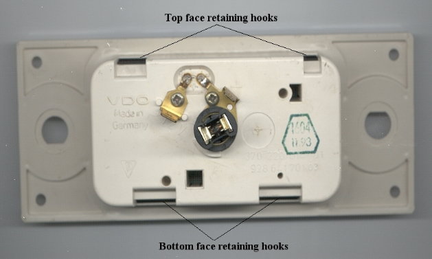
Remove the black plastic face piece from the clock assembly by pushing in the four retaining hooks on the back and pulling it forwards. Be careful not to loose the two small buttons that are used to set the time. The buttons just lay in the two holes in the black face piece and will fall out if the piece is turned.
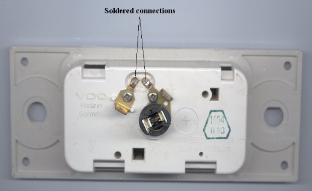
Remove the solder from the two connections on the back of white plastic clock housing with a soldering iron and a desoldering tool. Remove as much of the solder as you can, otherwise you won't be able to get the clock out of the housing in the next step.
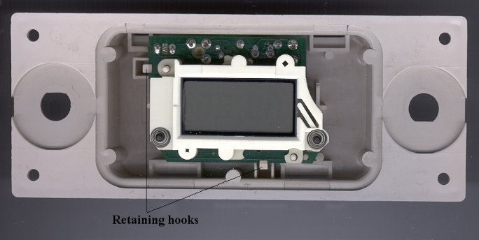
Remove the clock circuit board/digital display assembly from the white plastic clock housing by releasing the two retaining hooks on the front of the housing and pulling it forwards. Use caution so as not to break the hooks off when pulling them back. If the assembly doesn't come out easily after the retaining hooks have been released, you probably still have some solder on those connections on the back holding it in.
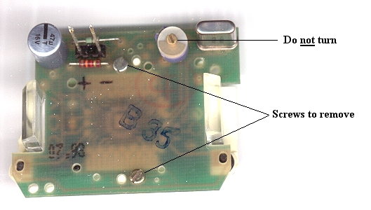
Remove the two small screws on the back of the circuit board. These screws hold the circuit board and the digital display together. After the two screws are removed, lift the circuit board up away from the digital display housing. Do not turn the small adjusting screw in the center of that round plastic piece that's on the back of the circuit board.
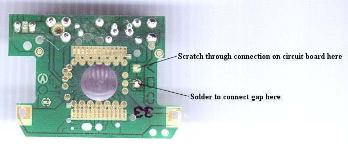
On the side of the circuit board that was towards the digital display, you will see the letters VDO printed on the circuit board. Directly beneath the letter V there are two small copper areas. They look like a copper circle that's been split in half. These two copper areas are connected on the circuit board. Take a pin, or similar small pointed tool, and completely break the connection attaching the two copper areas. Use care not to scratch through any other connections on the circuit board when you're doing this. Holding the circuit board up to a light will make it easier to see if you have successfully removed the connection completely.
Directly beneath the letter D of the printed VDO, you will see another two copper areas that look like the first pair. Solder these two copper areas across the gap.
Screw the circuit board back to the digital display assembly with the two small screws, making sure the alignment pins match up to their holes properly. Be careful not to strip the screws when tightening them in the plastic. Press the circuit board/digital display assembly back into the white plastic clock housing. Solder the two long pins back to the copper connections on the back of the clock housing. Before you reinstall the black plastic face piece to the clock assembly, make sure the two small plastic time setting buttons are in their holes.
Just to post a follow up, knowing that the circuitry is relatively simple (circuit board, zebra connectors, LCD screen), I decided to disassemble everything and give it a good cleaning with isopropyl alcohol and cotton swabs.
When re-assembling, remember the bump on the LCD screen goes on the opposite side of the alignment tab in the screen housing.
I powered the circuit board with a 12V 1.0A AC adapter with the ends stripped and tinned and insulated alligator clips. Having the board powered while re-assembling will ensure the segments all light up and the clock is operating as intended (hour/minute adjustments).
There is a thin anti-glare coating on the LCD screen, and it's easily scratched, so if you end up scuffing it, now is the time to take some polishing compound and remove the rest of that coating. You can also polish the plastic window on the clock housing at the same time.
The cleaning worked great, and the clock operates exactly how I wanted (12 hour civilian time). Hope this helps others who might have difficulty doing this same mod.
Hi traxtar928
I can't help you with your question since I can't get my clock out from the central console.
Can you please tell me how to take the clock out of the car?


 08-02-2015 | 05:11 PM