When you click on links to various merchants on this site and make a purchase, this can result in this site earning a commission. Affiliate programs and affiliations include, but are not limited to, the eBay Partner Network.
If you didn't solvent-flush the system, particularly the evaporator, you may find that there's enough mineral oil lft to jelly up the new oil.
The workshop manuals provide guidance on how much oil to put in. Since you are replacing the drier and flushing/refilling the compressor, use the factory fll spec rather than looking at how much you took out. The compressor gets 280+/- 20cc. The guidance is then percentages based on what components you are replacing. The split has 40% of the total oil capacity in the compressor, 35% in the evaporator, 15% in the condenser, and 10% in the drier and the hoses/lines. A little inverse derivitive abacus math tells us than that the total capacity of the system is 700cc, evaporator has 245cc, condenser has 105cc, and the lines and drier hold 70cc. You can see that there would be some concern about putting PAG oil into a system that still has that much mineral oil still hiding out in the system beyond the compressor.
The dr's recommendation is that you should drop the compressor again, drain and fill/flush a few times with POE to get all the old oil out, drain as completely as you can, then add 280+/-20cc's of POE to the compressor. Ideally you'd do a solvent flush on the condenser and evaporator since they are the largest holders of old oil. Then use a little bit of the system vacuum to draw 350cc of POE into the system via the high-side charge port. That port sits between the condenser and the drier in the process loop, and flows on to the evaporator when you first run the system after vacuuming and recharging it.
You MUST replace the drier regardless. The drier has a bag of dessicant beads inside that are coated with oil once the system is used the first time. The old mineral oil doesn't carry well in R-134a, yet it coats the bag and the dessicant beads, so it will quickly plug up. The coated beads won't do any drying either. All the driers now available are compaitible with R-134a and the POE oil.
----
More than a few cars have been "converted" to R-134a using parts store kits, virtually all of which included PAG oil bottles. Small wonder that a vast majority of those "conversions" ended up with failed compressors, clogged expansion valves or orifice tubes, and at a minimum they had marginal cooling available. More than a few 928 owner came back to the forum here after performing one of these "conversions", asking why the center vent temp wouldn't go below 55� unless outside air temp was already under 55�. It also contributes to the myth that R-134a doesn't cool a 928 as well as R-12 can. Cleanliness, attention to the details, and your acquired knowledge of how the system works are essential to the success of any AC project. A full conversion means getting all the old sealing parts replaced, all the old oil out, new R-134a-compatible drier and expansion valve(s), the correct lubricant installed correctly, adequate vacuuming to get all remaining moisture out, removal of absolutely as much air as possible from the system, then carefully charging the system without reintroducing air back in.
That last item is very critical (as are all of them really), since a lot of hard work and system performance are sacrificed when even a small amount of air gets in or is left in. Air comes in via un-evacuated and/or unpurged charging hoses, uncapped Schraeder ports when the system is under vacuum, etc. Air in the system is a performance killer plain and simple.
Thought I'd put this thread to bed with the conclusion to this work. My A/C is now blowing beautifully cold and it's a glorious thing.
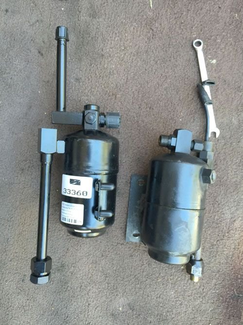
Autozone sell new receiver driers for $24.99 which I thought I'd try out. Time will tell if lasts. Seems to be doing the job and is a better design than the stock drier as the high-side charge port helpfully protrudes for better access (see pic).
I didn't drop the compressor again. I couldn't bear to do it. Again, we'll see how long it holds up. Had the system vacuumed and charged properly at my usual shop. No leaks, works really great. I'll report any problems if they could be useful to this thread. If anyone's interested, this shop (in hollywood) can recharge R12 systems. Twice as expensive though.
Thought I'd put this thread to bed with the conclusion to this work. My A/C is now blowing beautifully cold and it's a glorious thing.
Autozone sell new receiver driers for $24.99 which I thought I'd try out. Time will tell if lasts. Seems to be doing the job and is a better design than the stock drier as the high-side charge port helpfully protrudes for better access (see pic).
I didn't drop the compressor again. I couldn't bear to do it. Again, we'll see how long it holds up. Had the system vacuumed and charged properly at my usual shop. No leaks, works really great. I'll report any problems if they could be useful to this thread. If anyone's interested, this shop (in hollywood) can recharge R12 systems. Twice as expensive though.
Please put a note in your calendar to update this thread in a year if you haven't had to revisit it first. I'm hoping you have nothing to report except "My fingers are cold."
Please put a note in your calendar to update this thread in a year if you haven't had to revisit it first. I'm hoping you have nothing to report except "My fingers are cold."
Time is definitely the true test of how well the system is sealed up, how well the "conversion" is done, and how well the system was cleaned and refilled.
Remember to run the system weekly even in non-hot periods to keep the compressor shaft seal lubricated. My otherwise-tight system easily maintained charge in SoCal with regular driving and use. Now in winter-hibernation territory, the shaft seal dries out and leaks if left unused for a while. It would sit unused for max one month when I travelled on business from SoCal, with minimum loss. With 4+ winter hibernation months here, it needed a pretty good puff of refrigerant to restore finger-freezing performance this spring. It's not severe enough to deserve a compressor reseal, at least not yet. Might be a cool winter project to do that though.
I hope that the PAG works out for you - it will be an expensive, frustrating experience if it doesn't.
Some firmly-held opinions:
Three oils: R-12 uses mineral; original factory R-134a uses PAG; conversions use POE.
Nothing but R-12 or R-134a. Either works well in a properly-serviced system. No magic refrigerants, no propane, no sealant, nothing.
The cooling fans need to work perfectly. This includes the thermostatic clutch on the early cars.
Not quite been a year. There's a problem. The condenser fan is not coming on for some reason. Currently searching the archives of this site for a possible explanation but if anyone wants to chime in, please do.
Some people are saying it should come on when up to temp, others are saying it should come on regardless of temperature when the a/c is running.
Groan. Again, if anyone wants to offer suggestions, please do. Much appreciated.
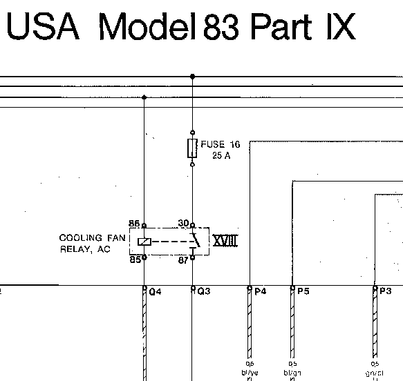
Per the wiring diagram for your 1983 car (see sheet IX, loops 9 &10), there are two switches that feed a relay for the aux cooling fan. There is a "temperature switch, refrigerant" tha normally lives on the plumbing by the receiver drier. It reads the temperature of the refrigerant coming from the condenser, and triggers the "cooling fan relay, AC" in position XVIII by grounding relay terminal 85 via CE panel connection Q4 (blue with green tracer). The other side of the relay coil at relay terminal 86 gets voltage via the X bus, which should be energized when the key is in the "engine run" position only. The other switch is the "temperature switch, coolant", which screws into a port on the lower left (driver's side on US cars) front of the radiator tank. This is accessible below the AC condenser. This switch is connected on parallel with the refrigerant switch, so that either switch will ground the relay 87 terminal and cause it to close if temps get too high.
The actual power for the fan comes from the CE panel 30 bus, always on. The circuit is protected by a 25 Amp fuse in position 16 in the CE panel. Current flows from the fuse to the 30 terminal at the relay socket. When the relay contacts are closed, current continues through relay socket terminal 87, through CE panel connection Q3 (red), to the aux cooling fan motor.
Start your troubleshooting with the simple stuff, like checking to make sure the fuse at position 16 is intact. You can then test for voltage at both legs of the installed fuse using needle probes. Both should show battery voltage regardless of key position or AC operation.
If the fuse is good and is confirmed with voltage on both fuse legs, you can test the relay and the fan together by carefully grounding CE panel connection Q4 (the blue-green wire) with a jumper, with the key in the "run" position. The relay should click and the fan should run. If it does, jump down to "testing the switches" below.
If the relay clicks and the fan does not run, verify that the fan motor is plugged in, and that the ground connection to the fan motor is clean and secure.
If the relay does not click and the fan doesn't run, replace the relay with a known-good 53b type, perhaps borrowed from horn relay duty if you don't have a new spare.
If the new relay doesn't click, remove it from the socket and check for battery voltage at relay socket terminal 86 with key in 'run' position. If no voltage, replace the X-bus relay and test again.
If you have voltage at the socket 86, verify continuity between relay socket 85 and CE panel connection Q4. With voltage at 86 and with 85 grounded via Q4, the relay should click.
While the relay is out, verify battery voltage at socket terminal 30. If no voltage, verify again that fuse 16 is intact. Verify continuity between the fuse connections and relay socket terminal 30. If there is no voltage at relay terminal 30 and there is voltage at both sides of the installed fuse, you have a wiring fault between the fuseholder and the relay socket behind the CE panel.
Verify the loop between relay socket terminal 87 and ground via the motor wiring and the motor. Using your ohm meter function, you should be able to measure the resistance at less than about 5 Ohms. If resistance is higher or infinite, check resistance between relay socket terminal 87 and CE panel connection Q3 (red). If resisitance there is more than 1 Ohm, there's a fault in the CE panel wiring.
Check resistance between CE panel connection Q3 and ground. It should be less than 5 Ohms. If it's more or infinite, check resistance between Q3 and one of the pins (red wire) in the harness connector at the motor, disconnected. You should read less than 1 Ohm. If not, there's a wiring fault between Q3 and the motor connector.
Check resistance between the other motor connector (brown wire) pin and ground. If it's more than 1 Ohm, you have a bad ground or broken wire to ground.
Check resistance between the two pins of the motor connector from the motor, disconnectd from the car. You should read less than about 5 Ohms. If higher or infinite, you have a bad fan motor.
Testing the switches:
There are two temperature switches. We are most interested in the refrigerant temperature switch on the refrigerant piping. It has a blue-green wire running to it, and a brown wire. Disconnect the switch, and test for voltage on the blue/green wire. You should see battery voltage with key in the "run" position while the fan relay is installed. If no voltage, move back to CE panel connection Q4, the other end of that same blue/green wire, and test for voltage there. If you have voltage at Q4 but none at the switch connection, there is a wiring fault in that blue/green wire.
If you found voltage at both ends of the blue/green wire, ground the blue/green wire. The relay should click in and the fan should run. If not, go to the top and start over with the diagnostics. Otherwise, jumper the temperature switch connection. The relay should click in and the fan should run. If not, you have a fault between the switch connector (brown wire) and ground. If the fan runs with the jumper in place, the refrigerant temperature switch is faulty.
Thanks for such an extensive reply. I appreciate your taking the time, I really do.
I do have said wiring diagram but it's not a great reproduction that's hard to read but I was just about able to follow along with your commentary.
I'm just gathering all this together in my brain before messing with the CE panel ...
Originally Posted by dr bob
If the fuse is good and is confirmed with voltage on both fuse legs, you can test the relay and the fan together by carefully grounding CE panel connection Q4 (the blue-green wire) with a jumper, with the key in the "run" position. The relay should click and the fan should run.
Hopefully this isn't too dopey a question: how do I do that? I'm looking at photographs of the CE panel and I'm assuming the blue-green wire is part of the spaghetti of wires beneath the fuses?
Originally Posted by dr bob
If the relay does not click and the fan doesn't run, replace the relay with a known-good 53b type, perhaps borrowed from horn relay duty if you don't have a new spare.
I don't have a spare. Is the horn relay interchangeable with XVIII?
Thanks for such an extensive reply. I appreciate your taking the time, I really do.
I do have said wiring diagram but it's not a great reproduction that's hard to read but I was just about able to follow along with your commentary.
I'm just gathering all this together in my brain before messing with the CE panel ...
Hopefully this isn't too dopey a question: how do I do that? I'm looking at photographs of the CE panel and I'm assuming the blue-green wire is part of the spaghetti of wires beneath the fuses?
The connectors the bottom of the CE panel have letters assigned to them, starting with "A" on the left. Further, the plugins have their letter on the sockets. I don't have a picture since I'm not near the car, but others may be able to help here.
The wires in the connectors are numbered based on their positions. IIRC, they start at bottom left and go up 1-2-3~, bottom right and go up 11-12-13~. Regardless, you'll be looking for the blue-with-green-tracer wire in connector Q. There will only be one.
In my vast collection of accumulated things, I have stuff like old meter test leads. I also have banana-connector alligator clips that accept the meter end of the test leads. So for me, I connect alligator clip to ground and stick the meter probe into the socket next to the wire going in, until the tip of the probe contacts the back of the wire crimp connector that's inserted in the Q connector. If you don't have the same accumulation of electrical junk that I do, you can use a standard jumper with alligator clips on either end. Substitute a bit of a straightened paper clip for the meter probe end, use that to contact the crimp connectot insde the Q connector.
The resoning behind this test step is that grounding Q4 duplicates the function of the temperature switches, isolating the testing to a specific set of components. Troubleshooting is a logical process of elimination, startingwith a best guess at what is the most likely, cheapest to fix and easiest to test. In the protocol I described, the testing steps cut the available failure points in half, We look at the power side first, then the switching side. In your case, since you last worked on the drier and the temperature switch wiring as part of your AC work, it's probable that the temperature switch isn't plugged in completely, or the wiring there is damaged. Or the switch was dropped and no longer functions. Regardless, the testing is easy when you break it down to steps and localize it for the most part to the CE panel area. Still it makes a certain amount of sense to revisit the last work you did since the system last functioned, and see what you might have missed on reassembly. I trust you have done that already, but that trust may be misplaced.
I don't have a spare. Is the horn relay interchangeable with XVIII?
Yes.
And a few of those relays as spares need to live in your "essential spares" collection in the car. They are inexpensive from our regular suppliers, under $10 each or so, and can easily make the difference between driving home and getting flatbedded home. Your car and the original relays are now over thirty years old. Make a list of all the 53b relays in the CE panel, and replace the critical ones now in the comfort and convenience of your driveway.
Also: Converting the car to R-134a means you are using a refrigerant that has a higher pressure at the same condenser temperatures than the R12 that came iin the car. The curves are similar until you get above about 90� ambient, beyond which the pressure differences get more acute. The system is somewhat self-protecting, but there is little tolerance for condenser fan failure. ASSuming the mechanical fan is still working correctly, there will be some airflow. Should airflow fall off though, condenser pressure will build quickly and risk damage to the compressor. There's [supposed to be] a blowout plug on the drier that dumps the refrigerant charge if/when pressures get too high. Meanwhile, the later factory-fitted R-134a cars (starting with actual mid-'92 production rebadged as '93 IIRC) cars have a dual pressure safety switch that cust off clutch current on overpressure. For pre-S4 conversions where fan failure is more likely and airflow is less, installing and adapting the wiring for one of the later switches is a Very Good Idea for R-134a converted cars. The pressure safety switch sits on a Schraeder-valve protected port by the drier, so can be easily replaced without losing refrigerant.
Thanks again for such great troubleshooting instructions.
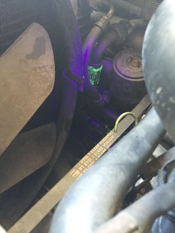
So I quickly determined fuse 16 was good, the XVIII was good (as was the horn relay), I grounded the blue-with-green-tracer wire in 'connector Q' and sure enough, the fan started spinning. It was then that I noticed that the compressor was no longer engaging. I dug out my UV light and sure enough, found a breach; there was some UV dye that I added to the compressor, waving at me.
The shop I took it to gave the system the 'all clear'. 'No major or minor leaks' they proudly said. So could this leak have 'just happened?'
Thanks again for such great troubleshooting instructions.
So I quickly determined fuse 16 was good, the XVIII was good (as was the horn relay), I grounded the blue-with-green-tracer wire in 'connector Q' and sure enough, the fan started spinning. It was then that I noticed that the compressor was no longer engaging. I dug out my UV light and sure enough, found a breach; there was some UV dye that I added to the compressor, waving at me.
The shop I took it to gave the system the 'all clear'. 'No major or minor leaks' they proudly said. So could this leak have 'just happened?'
Can anyone identify this leak?
Sorry for being so darned tedious.
If that's an original hose on a 32 year old car, then yes, it could have just happened.


 07-02-2015, 04:17 PM