When you click on links to various merchants on this site and make a purchase, this can result in this site earning a commission. Affiliate programs and affiliations include, but are not limited to, the eBay Partner Network.
FWIW I like that your putting in vapor barriers, these details make the doors solid..
I would add that it appears that the drip panels are missing from the left door.
NOTE drip panels are pieces of plastic attached to the top of each opening ,
and then left to hang inside the lower edge of each opening by about 1 to 2 inches.
The way you have it now water will run down the installed liner and possibly pool at the caulk,
this in turn will leak out and damage the door panel.
With the vapor barriers and drip panels installed the doors will sound like a vault when they are closed,
The door panels will stay dry and the barrier will also reduce road noise.
Note if the carpet comes off the door I suggest to use Weldwood brush on contact cement,
found at HD use the stuff in the red can
^ Looking at the original torn plastic barriers I can see the drip panel for which you are referring. Unfortunately, I don't have the patience right now to remove them and address the issue. I'll go back later and add the drip sections in a few weeks.
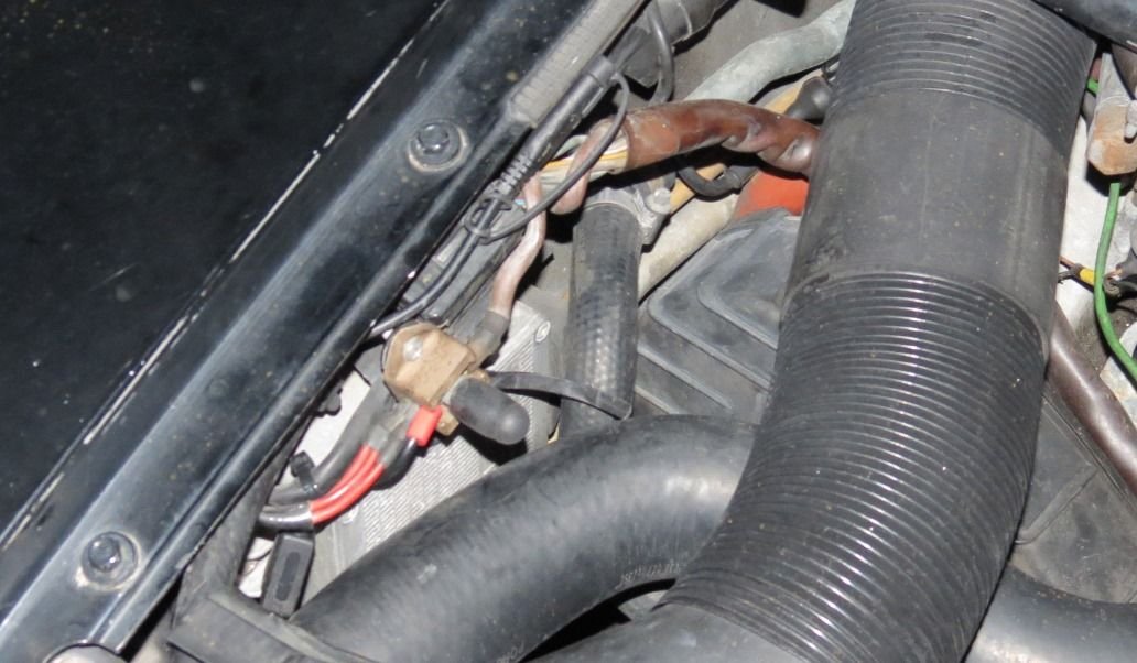
I was able to run the 'S' line from the alternator to the battery this weekend. As suggested, I used a 16G wire since it carries no load to/from the battery. It appears the 'S' wire coming from the alternator was 12G, but I don't think running a 16G will be an issue. I covered the entire wire with a protective sheathing I purchased and in the engine compartment I covered the wire in heat resistance wire covering. You can see the silver foil covered wire loom in the picture below.
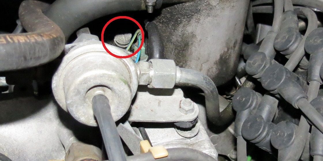
In the picture below and circled in red is the 'S' line from the alternator to the battery. I used a smaller rubber grommet to protect the wire after I drilled the hole. The line circle in blue is the stock wire, which had been cut real short and was barely attached to the ring connector. I lengthened this line with an additional ~1ft of 8G wire and reattached.
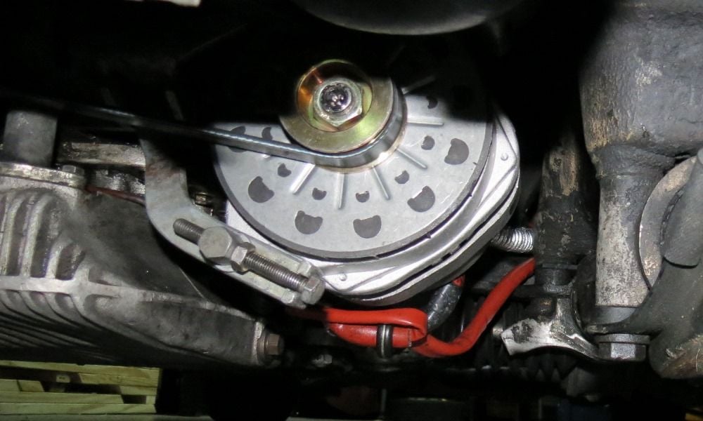
I then installed the smaller 52mm pulley on the alternator. Although it may be hard to see, the red marks I previously made showed the alternator was not hitting the power steering pump and I was able to use the same new alternator belt.
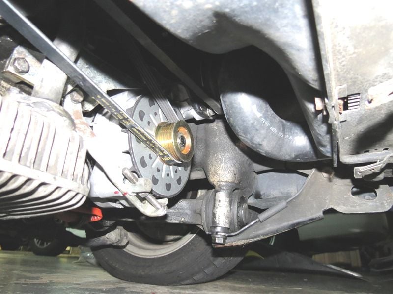
So what I have found is the alternator works well when you first start the car, but once the car reaches operating temperature the idle drops below 700rpm and the voltage begins to drop on the alternator. I was able to adjust the screw shown in the picture below to raise the idle to ~800rpm, which seems to resolve the idle issue. However, after adjusting yesterday and coming back today the car again idles below 700rpm. Does anyone know of the idle can be controlled with the screw or is it being targeted by the ECU?
The next thing I did was to start cleaning all the ground points on the car so i started with the main strap from the chassis to the engine. It is fair to say this needed cleaning. I then cleaned the one of the drivers side just in front of the headlight bar as shown in the picture below.
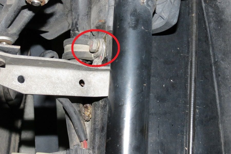
I then moved the ground location on the passenger side at about the same position as shown below. This is easy to get if you use a ratcheting 10mm box end wrench.
While this ground was off I used the ground point to wire in a battery tender. The picture below is the new tender charger location with the positive end hooked to the jump terminal. While I was there I cleaned the contacts on the jump terminal and inspected the 14pin connector, which looked to be in great shape.
Although I didn't take pictures i was having issues with the front headlights cutting out so I pulled the relay. After disassembling and cleaning the contacts and connectors I put it back together and reinstalled. It appears to have done the trick because the headlights don't cut off or flicker.
I am not sure what task to take on next, but there is definitely not a shortage of small projects. I think I will check out the transmission to figure out why it revs so high before shifting. I suspect it is a bad vacuum line to the modulator, but we shall see.
you could order a hot post cover this will cover the 14 pin connector,
NOTE it appears that you have some corrosion on the wires coming out of the 14 pin,
try some spray deoxit on the pins and the wires, it may remove the corrosion
you could order a hot post cover this will cover the 14 pin connector,
NOTE it appears that you have some corrosion on the wires coming out of the 14 pin,
try some spray deoxit on the pins and the wires, it may remove the corrosion
Are you referring to the jump terminal? The jump terminal and connectors where cleaned so there is no corrosion. Regarding the 14pin connector, it required no cleaning because it was in good shape. Perhaps I am not seeing what you are referring.
Needs the plastic awning that clips to the fender above the 14 pin to keep out water. Looking at the fender lip you can kind of see where it used to be. The jump post pokes through it, and its cap holds the cover on.
Needs the plastic awning that clips to the fender above the 14 pin to keep out water. Looking at the fender lip you can kind of see where it used to be. The jump post pokes through it, and its cap holds the cover on.
Thank you for the clarification and after a quick search I found a picture of what you are referring. I will order one today along with the cap.
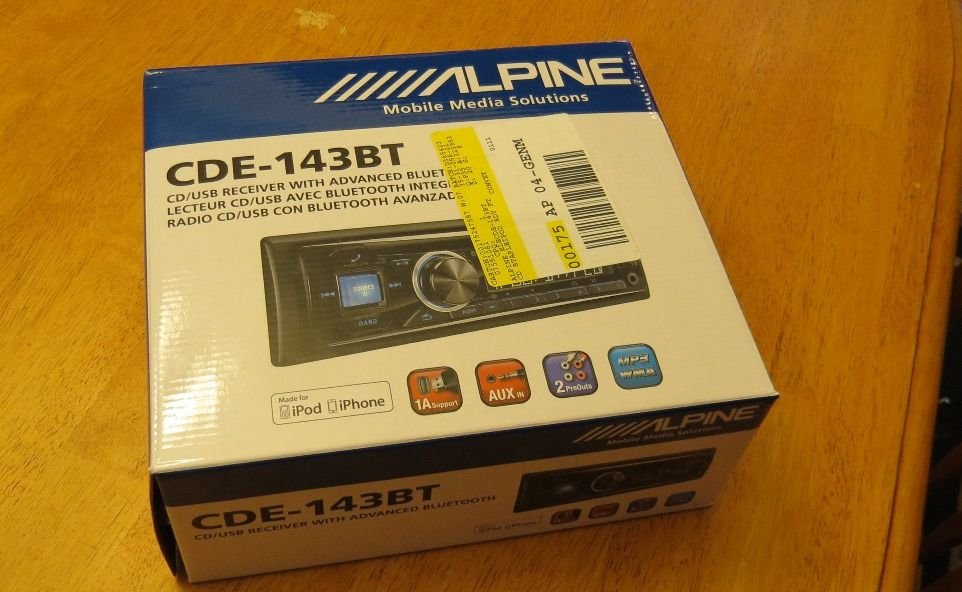
I decided to stay focused on the interior of the car to try and finish before working on the engine. I addressed the outdated stereo and purchased a decent Alpine in dash unit to replace the aging Sony that was already in the car.
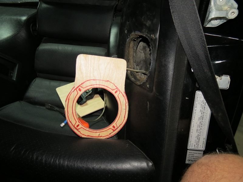
I then had to focus on the rear speakers, which as you can see where not actually car speakers. It appears a previous owner hacked up home speakers and tried to graft them into the rear. Needless to say the stock speaker mounting location was hacked and it damaged a large portion of the leather interior.
I purchased another set of the Kicker 5.25" two way speakers to use in the rear. In order to make them work I had to fabricate a new mounting plate to adapt the new speaker to cover the old hack job.
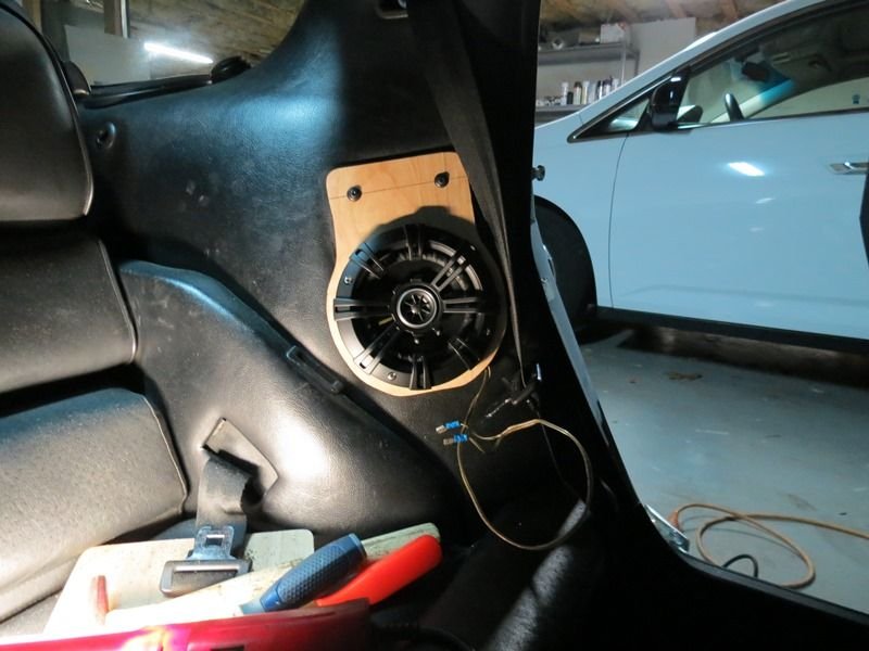
The pic below is of the new speaker mounted in the rear. The only thing remaining is to cover the wooden panel, but I can't decide to cover it with the carpet or the faux leather so any suggestions are appreciated.
I vote for pleather and then SEM paint the entire rear panel and speaker housing so they match.
Nice work dude looking good
Thanks, that was my vote too so I will order the SEM cleaner and paint next week. Unfortunately, the old speaker where not installed symmetrically and the passenger side was not hacked on the inside. I did my best to make them look the same given the circumstances. On a positive note the stereo is sounding pretty good so only need to install the new head unit to finish the setup.
You're missing the small black plastic trim that goes around the rear seat belt. I have TONS of them in storage, but won't get to them until next month. If you don't get some by then, send me a pm and I'll be more than happy to send you a pair!
You're missing the small black plastic trim that goes around the rear seat belt. I have TONS of them in storage, but won't get to them until next month. If you don't get some by then, send me a pm and I'll be more than happy to send you a pair!
Thank you...didn't know there was something missing!
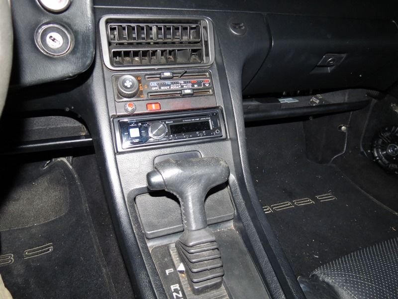
I was able to install the new Alpine head unit today, which was fairly straight forward. The only thing that took time was that I had to pull each speaker to verify polarity of the wires. Below is a picture of the new Alpine installed.
The Alpine unit also has phone capabilities via Bluetooth so I had to run the microphone to an area that was close to the driver's head. After I was done I realized my daughter's stereo was better than mine so it looks like I need to update my 2007 Alpine head unit.
I was able to install the new Alpine head unit today, which was fairly straight forward. The only thing that took time was that I had to pull each speaker to verify polarity of the wires. Below is a picture of the new Alpine installed.
If I may buttinski again, speaker polarity can be checked with a 1.5V AA battery without removing it from the grill or your enclosure, as long as you can see the cone from the front. Put a couple of test wires on the battery, and touch them to the speaker wires while watching the cone. You can orient all the speakers the same just by working from the rear of the amp connection.
<edit: I found a vid that shows it, but he uses a bigger batt
This is pretty important, so despite the symbols on the amp, wires or speakers, I would test them all manually to insure they are correct phase. Some mfg define "+" as winding from the cone to the backframe, and some define winding from the backframe to the cone as "+". Best to test with the batt.
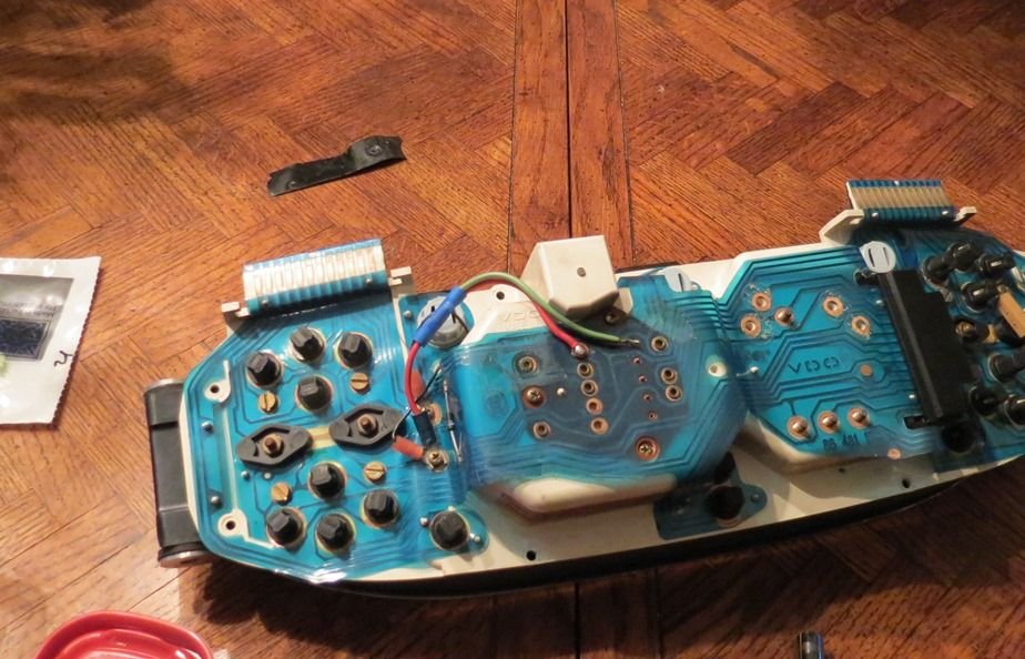
Upon removal I noticed some strange wires on the back of the gauges.
After I removed the tape I knew it was something added by a previous owner. The only thing I can think is the odometer gear gave out and the owner assumed it was a power issue.
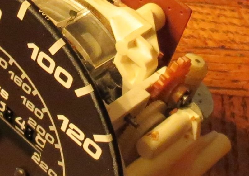
Once I removed the speedometer I could see the stock gear was broken and the small pieces of gear where scattered around.
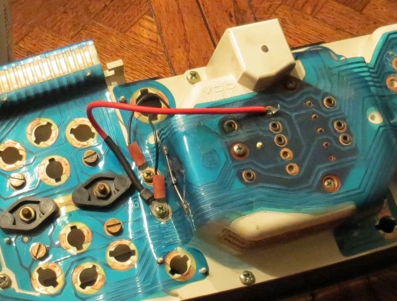
I replaced the gear and removed all of the small fragments and the odometer was working perfectly. I then removed the wiring that was used to jump the terminals, but because they had soldered to the crimp it was affecting the continuity to the board. Therefore, I had to add back a jumper to make sure it retained power at the solder point and its connection to the pin beside it.
The next task will be to replace the bulbs with LEDs so stayed tuned.


 01-26-2015, 12:04 AM