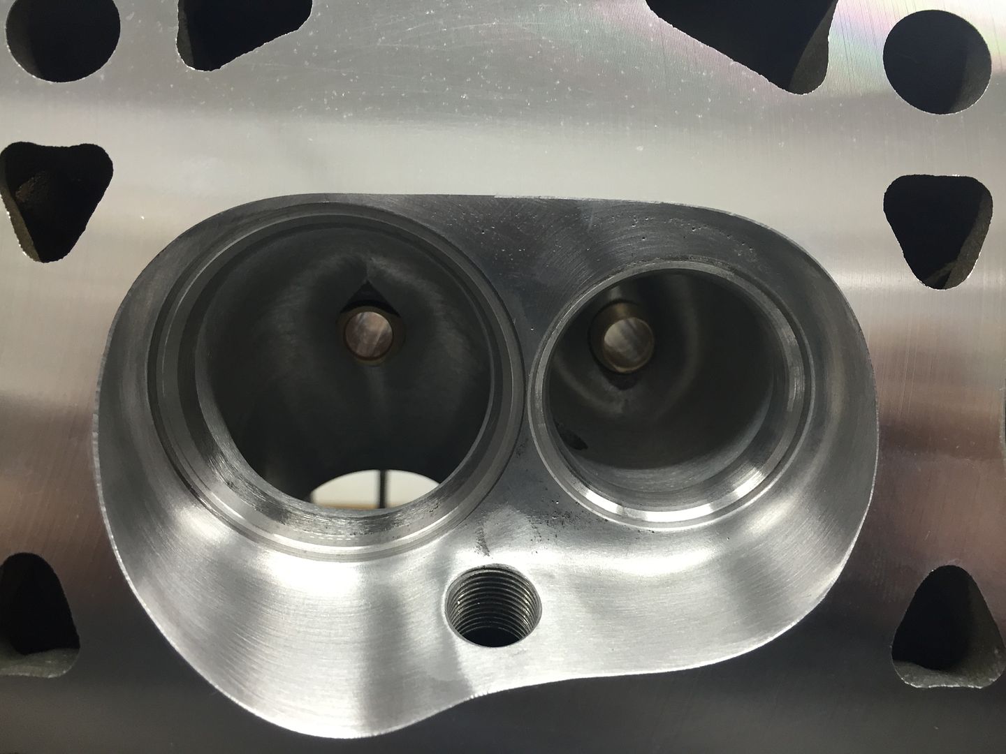
Porting 2V heads and Custom Manifold Test
#17
Addict
Rennlist Member
Rennlist Member
Thread Starter
The thing is technology is evolving so fast that our cars are getting quite old fashioned. This wasn't the case ten years ago. The hang up being the transmission to run. The manual synchromesh boxes susposodly won't change at high rpms and the auto box is ungodly complicated. The manual box will cost more due to the custom crown wheel and pinion. However you know you won't get stuck with a box full of neutrals.
#18
Addict
Rennlist Member
Rennlist Member
Thread Starter
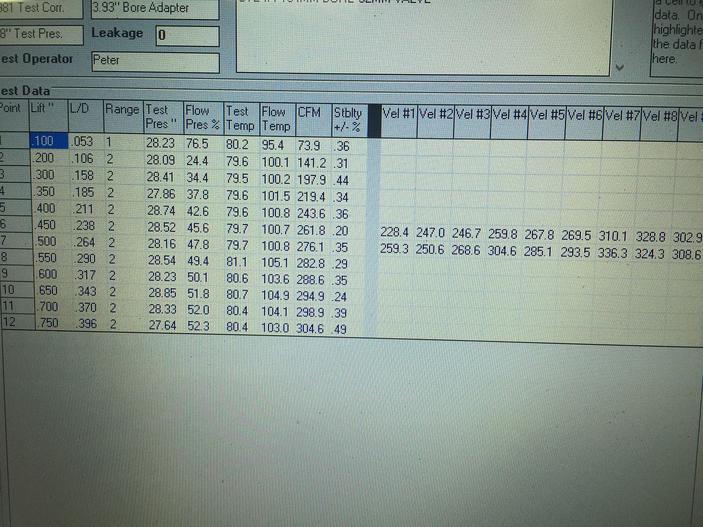
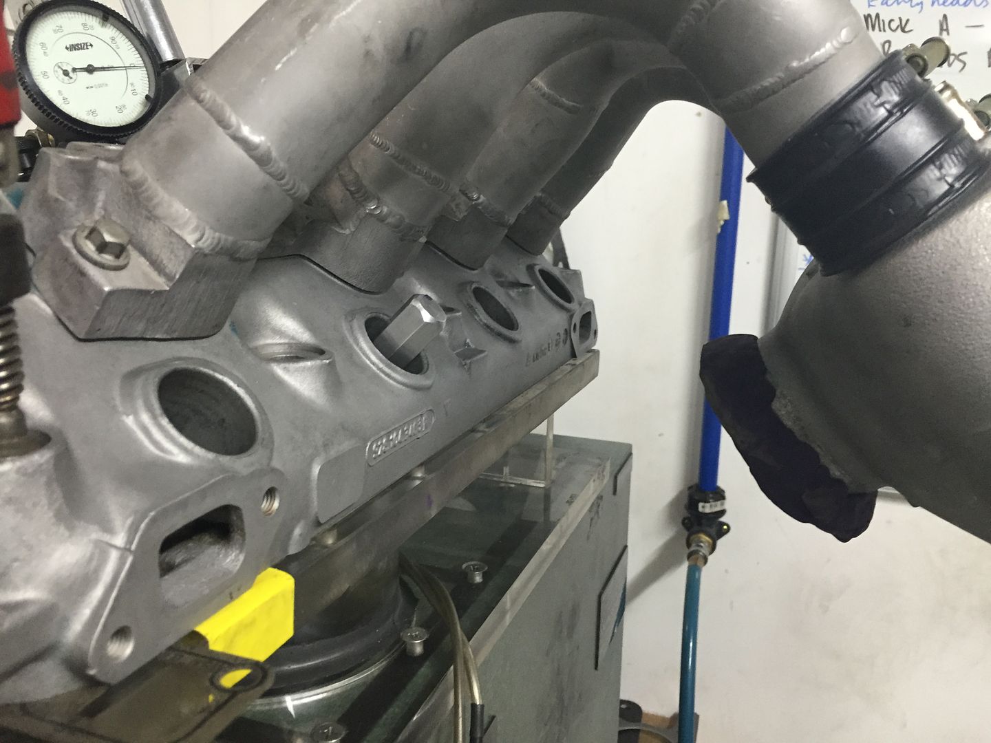
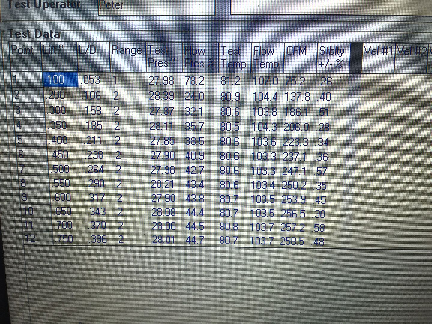
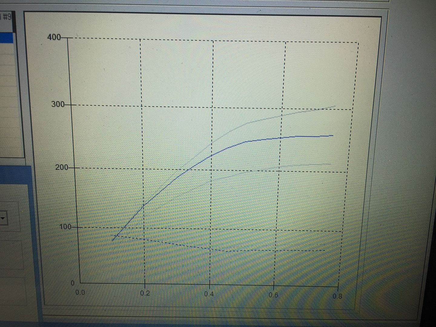
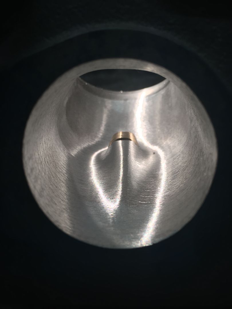
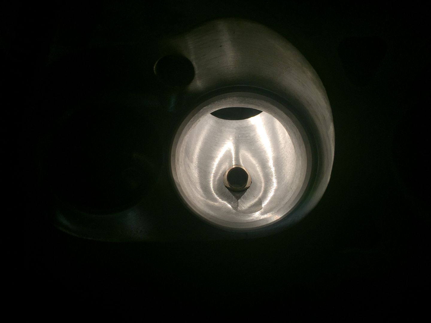
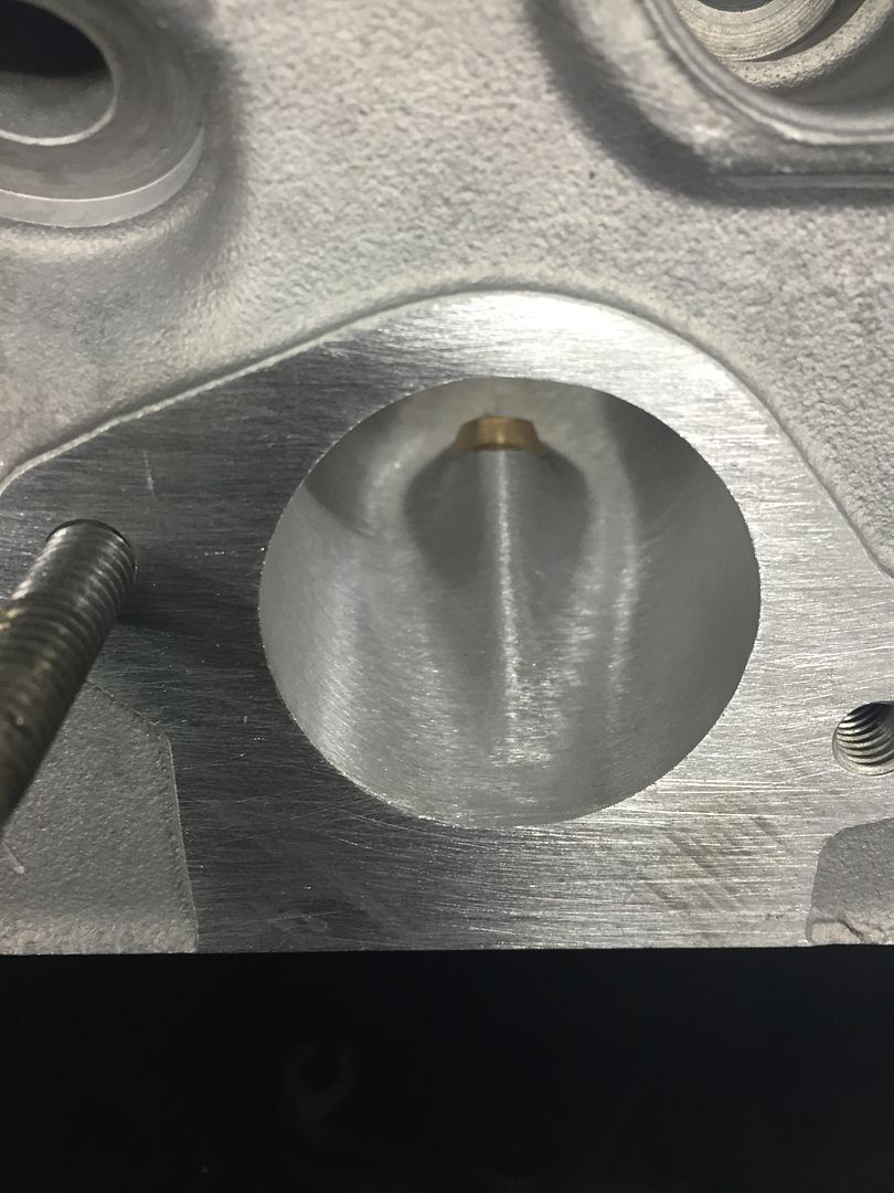
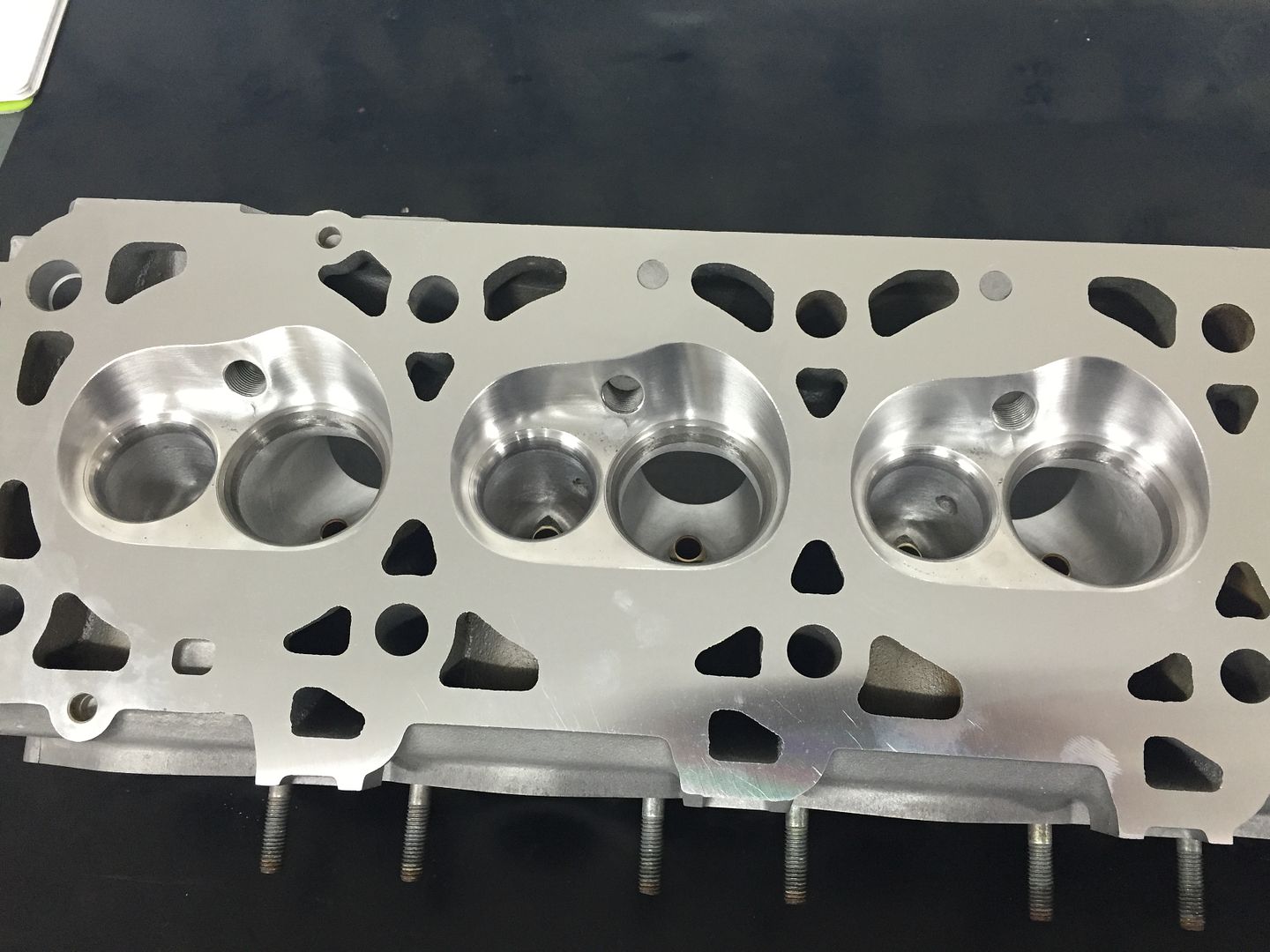
O.K the below post is by the cylinder head porter, the most important picture is that of the graph showing the standard intake air flow, the airflow of the modified intake valve with the plenum and manifold attached and the modified/ported intake without the intake, i.e just the port. You can see how the flow is being restricted by the intake and as such another custom manifold will be built over the next two months. We will do a custom plenum also and use proper bell mouths which I inspected yesterday. This should rectify the restricted flow and allow us to obtain our goal of 450 flywheel HP.
#19
Nordschleife Master
The manifold project will be interesting. What are you thinking about in terms of runner length? The intake ports being spread further out makes designing a single plane intake a bit simpler than in the later 4V models. It's still a significant effort. I bet people would love to hear more about your plans for the intake manifold. It'll also be very interesting to see whether it's the plenum or the runners that is the restriction.
What does pipemax say about the runner diameter for a 450 hp engine?
What does pipemax say about the runner diameter for a 450 hp engine?
#20
Addict
Rennlist Member
Rennlist Member
Thread Starter
The manifold project will be interesting. What are you thinking about in terms of runner length? The intake ports being spread further out makes designing a single plane intake a bit simpler than in the later 4V models. It's still a significant effort. I bet people would love to hear more about your plans for the intake manifold. It'll also be very interesting to see whether it's the plenum or the runners that is the restriction.
What does pipemax say about the runner diameter for a 450 hp engine?
What does pipemax say about the runner diameter for a 450 hp engine?
I will try to widen and lengthen the plenum. The length will help with the bell mouths. That is being able to fit them in without having to trim them into each other. So I am working within some limits and like the previous manifold and factory plenum hope to achieve a useful gain.
#21
Addict
Rennlist Member
Rennlist Member
Thread Starter
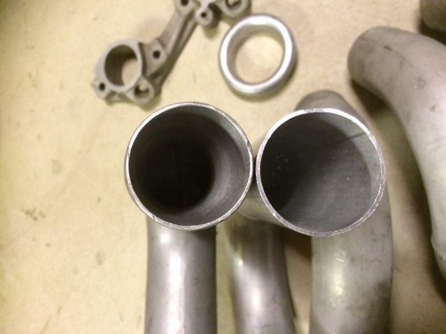
We've been super busy, so progress is slow but steady. First we have a comparison of the very first modified manifold which is the S runners but using the electronic injectors. These runners were ported and honed. The runner on the left is the ported runner, about 44.5 MM in diameter at the mouth, the other pipe will be used is 47.5 mm I.D and will be stretched to 48 mm as this is what the bellmouths are.
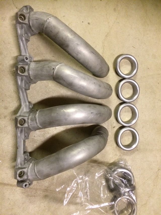
Here's a shot of the bellmouths and the situation arises where the bells are wider than the factory plenum spacing.
Below you can see here the amount of taper required in the intake runners as the ports will be only slightly bigger than the 944 manifold adaptor plate.
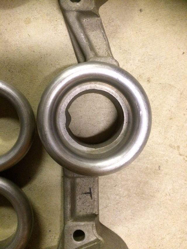
So essentially what is happening with the intake tract is that it will start off at 48 mm in diameter, the bell opening is wider however, and tapering to around 42 mm at the port mating surface.
Also the piston pins were worn so I ordered son new ones, these are tapered and weigh around 25 grams less, they also have a 45 degree recess and fit in a conventional high performance manner as apposed to the slack that is in the factory system. The engine will only be around 450 HP so the pin thickness will not be an issue.


Here's how the piston deck height issue was dealt with, an offset pin bush that was fitted accurately via a jig. The bush was bored out after the rod was held in the jig, just in case you are wondering.

I also had the rods notched for the harder King bearings which are race bearing and this will hopefully help if I get a small dose of aerated oil.


Here's a shot of the bellmouths and the situation arises where the bells are wider than the factory plenum spacing.

Below you can see here the amount of taper required in the intake runners as the ports will be only slightly bigger than the 944 manifold adaptor plate.

So essentially what is happening with the intake tract is that it will start off at 48 mm in diameter, the bell opening is wider however, and tapering to around 42 mm at the port mating surface.
Also the piston pins were worn so I ordered son new ones, these are tapered and weigh around 25 grams less, they also have a 45 degree recess and fit in a conventional high performance manner as apposed to the slack that is in the factory system. The engine will only be around 450 HP so the pin thickness will not be an issue.


Here's how the piston deck height issue was dealt with, an offset pin bush that was fitted accurately via a jig. The bush was bored out after the rod was held in the jig, just in case you are wondering.

I also had the rods notched for the harder King bearings which are race bearing and this will hopefully help if I get a small dose of aerated oil.

Last edited by slate blue; 04-04-2015 at 04:10 AM.
#22
Rennlist Member
Join Date: Feb 2011
Location: Mostly in my workshop located in Sweden.
Posts: 2,235
Received 467 Likes
on
250 Posts
Greg, before you balance the rotating assembly, it is a good idea to make the con rod small end lighter by removing the protrusion. To remove the protrusion at the big end is not recommended as the big end bore might go out of roundness which can end up in a bearing failure. The weight of the big end only add to the flywheel but the the small end add to the reciprocating weight which should be kept as small as possible.
┼ke

┼ke

#24
The heads in the thread are from a early S like yours, the 944 flange plate mod converts the manifold and gives a couple of options. (I couldn't find my thread about this custom manifold)
1, use the 944 flange plate and then use the S runners instead of the S2 runners which are horrible.
2, use the 944 flange plate and then use custom tubing like I did in the aussiev8 thread. or see below. In my case on one of my engines I used the S runners and converted them to the S2 style injector. This was a long time ago but it did work and those runners were fully ported along with the plenum. Which again is required. You will get a decent increase in airflow doing this. Lots of aluminium will end up on the floor!
https://rennlist.com/forums/928-foru...-2-valver.html
#25
Addict
Rennlist Member
Rennlist Member
Thread Starter
I used to have a side by side comparison of the two types of runners but the computer crashed.... However have a look at the S2 runner and I believe it is something like a 135 degree bend in it. The S runner would be around 100 degrees so is considerably straighter. My runners are only 90 degree and the CLR is larger maker the turn"softer". It would have been interesting to throw my modified S runners on the bench but this is all time and money and there is really nothing to gain.
So in short S2 runners are going to be compromised and they also have the squashed down portion near the injector which wouldn't help flow. Maybe that is there to assist in air velocity near the injector. The factory injectors are terrible in terms of atomisation this is another reason I converted my setup to use the later 4 spray hole injectors back in 2006. I used the 944 fuel rails and manifold plates to do this.
So in short S2 runners are going to be compromised and they also have the squashed down portion near the injector which wouldn't help flow. Maybe that is there to assist in air velocity near the injector. The factory injectors are terrible in terms of atomisation this is another reason I converted my setup to use the later 4 spray hole injectors back in 2006. I used the 944 fuel rails and manifold plates to do this.
#26
Addict
Rennlist Member
Rennlist Member
Thread Starter
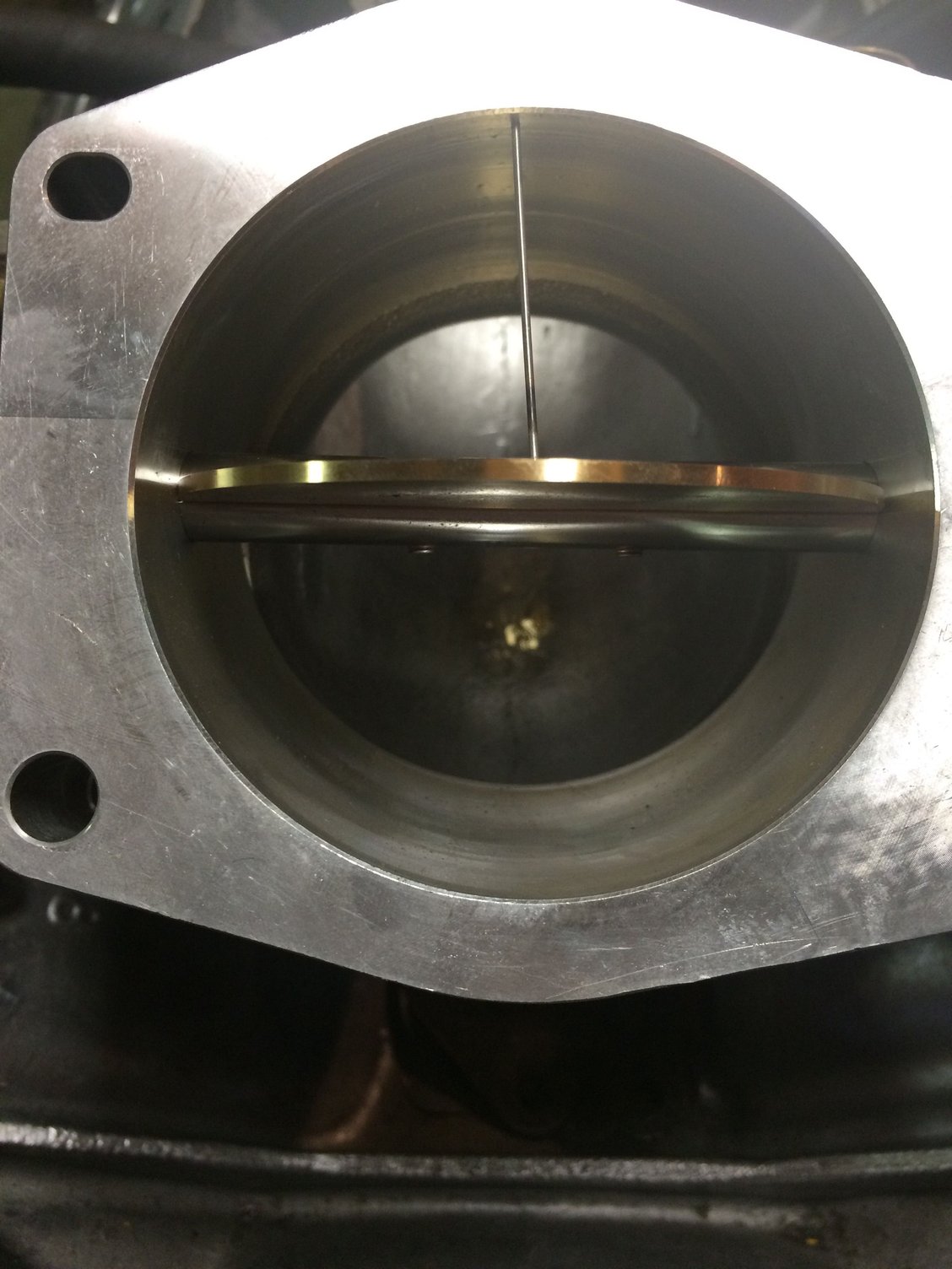
So we have an update, my idea for a custom manifold to be able to flow enough air for a slightly larger engine than stock. It also incorporates an electronic throttle for advanced traction and launch control. Some pics below.
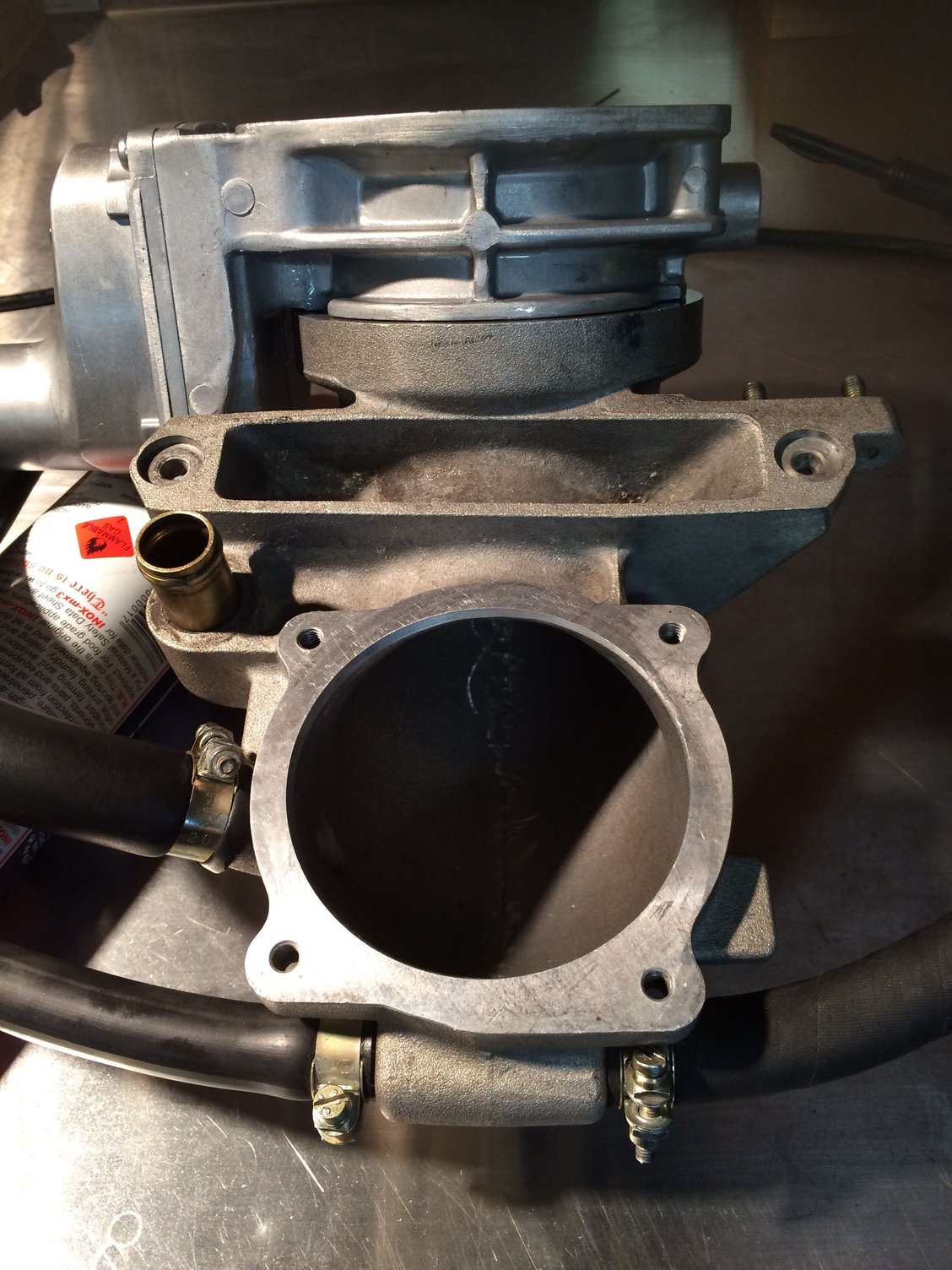
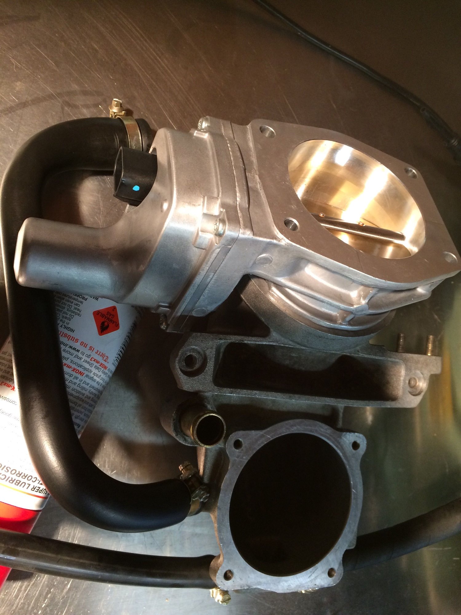
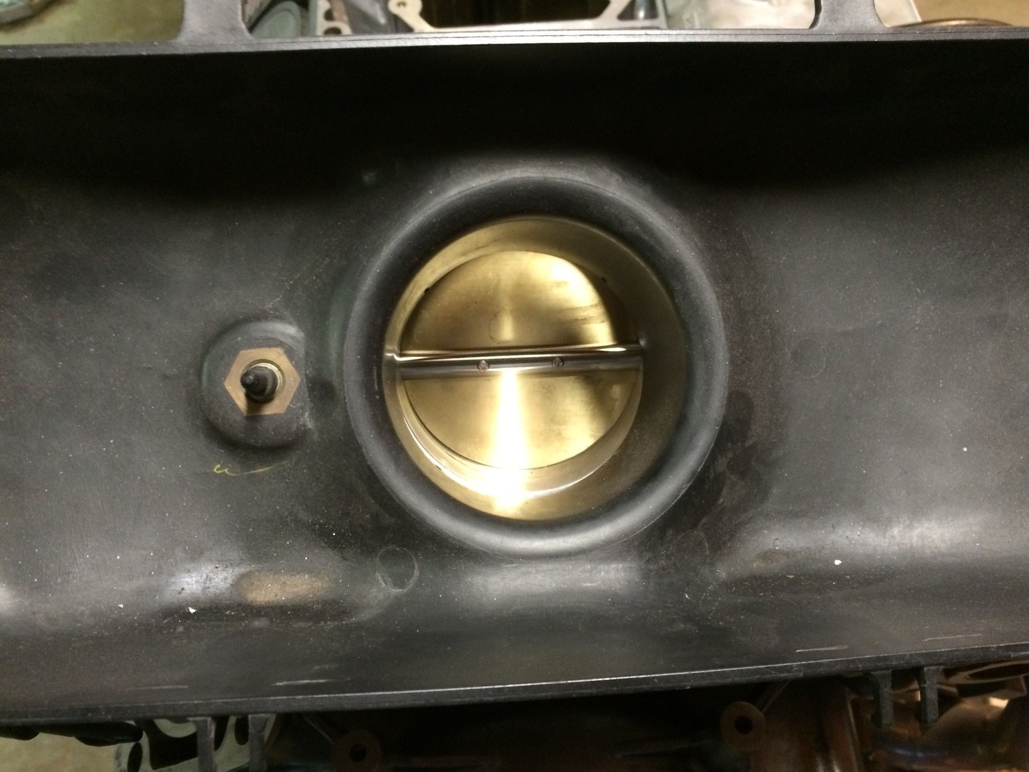
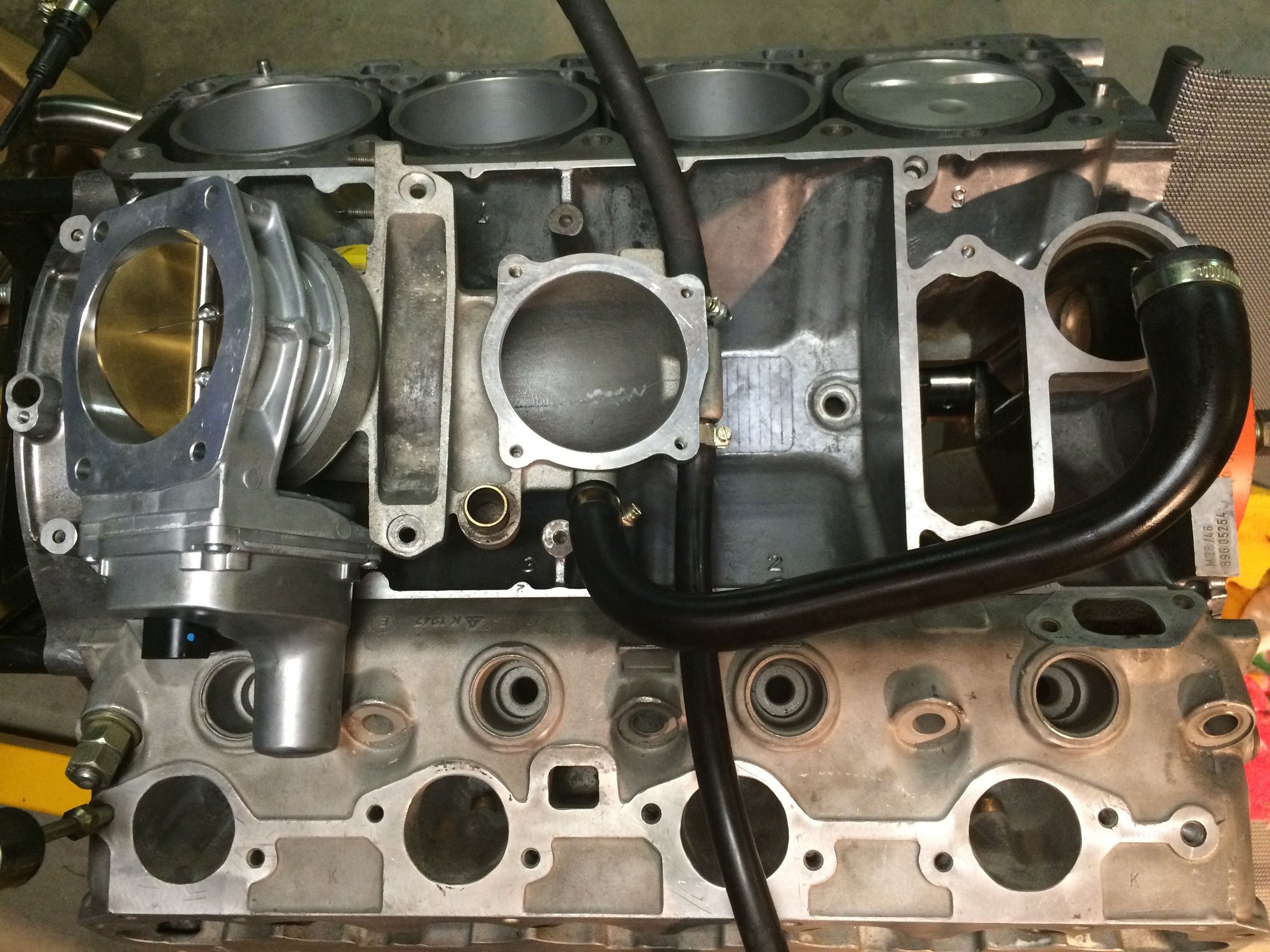
Centralised position for the air flow to the plenum
So there is more details than meets the eye, the plenum is effectively increased by moving the throttle blade backwards giving more volume.
The runner coming up from the U-bend will transition from round to oval to better spread out the air flow to all the runners. For those who aren't aware, the factory plenum distributes the air to the front of the plenum and I would suggest it is doubtful that this results in even air distribution. So the plenum is stretched an extra inch in length. It gets 48 mm bell mouths and an oval intake.
Obviously some of the plumbing will need looked at but hopefully this isn't a big problem.
The U-bend will get new mountings and the throttle body gets a billet piece to adapt it to the air cleaner and then they are clamped in much the same way as the MAF is.
#27
Addict
Rennlist Member
Rennlist Member
Thread Starter
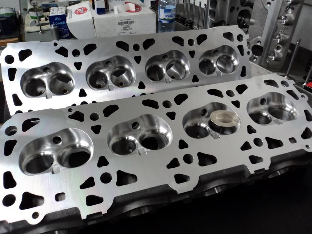
Just thought I would share this pic. ��
Anyway I will revise my idea for the 5.35 litre and 6.0 litre manifolds.
The existing modified manifolds are good for the stock 4.7 litre and 5.0 litres.
The two bigger engines, just to clarify, these are the 5.35 litre and the 6.0 litres versions. They will get bespoke manifolds according to their respective sizes. The 5.35 litre's engine will use the 48 mm runners seen earlier in thread with proper bell mouths and tapers that down to 42-43 mm at the port. These heads with the specced cams have about 275 cfm flow capacity and that with good velocity will provide very solid drivability.
The 6.0 litre which is getting a nicasil bore and lots of friction reduction technology should flow around 300 cfm and those runners will start off at 50 mm and taper down, probably in the 43-44 mm range. I am going to unshroud the intake valve by playing with its position in the bore. I should be able to move it at least 1 mm away from the bore and it will be around 53-53.34 mm in diameter.
I will stick with the LS throttle body but modify it to use the shaftless technology seen in my other threads. The throttle body will be placed at the front of the manifold and the air will have a much better direct shot at the plenum. So effectively the LS throttle body will be in the GM position and the air cleaner will be adapted to fit in front of the radiator. A bit like how the aftermarket does the GM cold air induction kits.
I'm also sorry for how lucky long this is all taking. There is however lots of other work that has been done behind the scenes and is ready for action. Such as the rotating assemblies for the 5.0 and 5.35 litre engines is finished. All the crank plugs were removed and the rods resized for harder rod bearings. Weight has been removed and two sets of crank scrapers have been made. These in my opinion work great in two valve engines.
I just don't get enough time to work on the cars and because of that my enthusiasm is waning. I haven't driven my car for almost a decade. I am in the process now of fixing mainly maintenance items on the wife's 928 S2. It has a somewhat tired engine but according to the G-tech does 0-100 in the factory time of 6.7 seconds, that was with half a tank of fuel and a passenger. I am putting my custom made duel 3" exhaust on that stock 4.7 litre just to see what happens. Will there be a performance difference either better or worse?
#28
Nordschleife Master
I just don't get enough time to work on the cars and because of that my enthusiasm is waning. I haven't driven my car for almost a decade. I am in the process now of fixing mainly maintenance items on the wife's 928 S2. It has a somewhat tired engine but according to the G-tech does 0-100 in the factory time of 6.7 seconds, that was with half a tank of fuel and a passenger. I am putting my custom made duel 3" exhaust on that stock 4.7 litre just to see what happens. Will there be a performance difference either better or worse?
I'm looking forward to hearing your results!
#29
Rennlist Member
Keep up the great work Greg ... I know from bitter experience how frustrating not being able to drive, or work on, a car is. You'll get there and we'll all applaud when you do. I know the result will be astounding. 

#30
Rennlist Member
Join Date: Feb 2011
Location: Mostly in my workshop located in Sweden.
Posts: 2,235
Received 467 Likes
on
250 Posts
Quote: I just don't get enough time to work on the cars and because of that my enthusiasm is waning. I haven't driven my car for almost a decade.
Greg, same here but two of our three cars are running. Everything take its time and there is so much else to do. Now when the restoration and paint job of the house, workshop and six-car garage is almost done, the wife has promised me I can spend all the time I want in the workshop doing what I like most, working on the engine projects. Actually I am not so much for driving, working in the shop I find more satisfying. If there is anything I can do for you in order to get your enthusiasm back, please let me know.
Pictures showing new workshop lighting and new horizontal milling attachment I recently acquired for the milling machine. Note the chain hoist for the lifting of the mill upper part in order to get the riser block in place.
┼ke


