When you click on links to various merchants on this site and make a purchase, this can result in this site earning a commission. Affiliate programs and affiliations include, but are not limited to, the eBay Partner Network.
I put the bayonet probe in both an old Behr and the new 928 MS rad with no problems.
Use an old wooden hobby paint brush handle that is tapered and about the same diameter as the probe to gently make a passage through the cooling fins at the top passenger side of the rad.
If I remember correctly, the kit comes with two types if temp probes.
A bayonet probe that fits between the radiator fins and a wet probe that requires a taped hole be drilled somewhere on the radiator.
Wasn't a big fan of drilling a hole in a new radiator...
Did the same on mine. Used a few qtips to open up an area and kinked them all, very tight fit. Slid the probe in gently. Still need to find a spot to sneak ignition and ac wire into interior. Gonna try to finish up this weekend. I have the threaded probe in my kit too if anyone needs one
Ahh, so it's either/or on the probes. That makes sense. I was thinking if you had to use both, there might be a way to use the existing temp sensor point on the radiator, but if there's no need...yeah I wouldn't want to be drilling holes there either!
using the "poke through" mounts. Difficult to do without either going through the radiator and the condenser, or taking one of the two out. Decided to just poke them though both. No issues really. And wont make
any difference from what I can see. Also used the poke through probe. Must use a slightly smaller slightly more pointed object. I used my Johnson
awl with the wood handle just polished the shaft a bit and used a little lube so as not to rip anything apart and cause seepage (always worried about that with these operations). Slid right in after that, well, with just a bit of friction to grip it tight. (I don't like the way this is sounding). Anyway...decided I don't to do any more pumping
air for the sake of pumping so I'm gonna pull the air pump before I start putting the final touches on it.
Last edited by The Patman; Apr 12, 2015 at 03:38 PM.
Still need to find a spot to sneak ignition and ac wire into interior.
try here...if ya have this. Switched (ignition) power sits on the AC temperature switch waiting o a ground from the AC temp switch (which I don't think has EVER come on my car...crappy system).
Anyway, switched power is on the ...looks like green or blue wire...
it's close, big enough, (it's only an on/off signal for the controller, it doesn't do any work) and already fused and (I think) relayed.
That is, if your model has this.
EDIT: OK that's not really a good place. While what I said above is true, it's not powered through a relay contact, it's powered through a relay coil. And even though it's a very small signal to the fan controller just to say the ignition is on, I don't think I'm gonna use that wire. I'll let ya know what I find.
Now I will say this, since we are using the FF Dynamics controller, there really is no need for the other fan relay. So it could be jumped I think, putting full power out at the fan connector...but ...well...I'll look at that. Otherwise we poke a hole through a rubber grommet somewhere.
Last edited by The Patman; Apr 12, 2015 at 08:37 PM.
Reason: New info that make previous post...Bullshi+
However, I did find out you can get the AC clutch signal ( on my model) from the aux air valve, as it get's the same signal the AC clutch gets in order to speed up or stabilize the idle.
Last edited by The Patman; Apr 12, 2015 at 08:58 PM.
Reason: AC Clutch
Thanks Patman, i was planning on looking around under the hood with my multimeter too. Unfortunately i need to take a week or so off, my car went to get a new Y pipe made, so the Borla exhaust can go on. Since it's a Euro i have no current cat. Thanks and if i get it back this week i'll report back anything i find too.
funny how a day turns into a week and a week turns into a month...
anyway, here's my final wire runs.
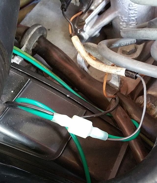
on the AC connection, I routed the green wire over to the AC air valve. I put on a plug connection and spliced into the tiny black wire that comes out of the wire harness there by the engine hoist loop. normally that would've been it, but I decided to replace the TINY black wire down to the clutch. with some left over green wire. it's fatter, carries more current...and made me feel better.
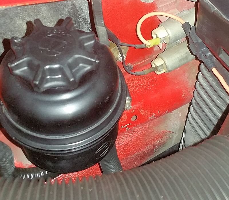
for the yellow wire 12vdc ACC ON signal I decided to tap into the resistor network on the drivers side behind the power steering tank. The black wire coming into the top one (on my model) is 12vdc from an accessory buss. Not my first choice as the best choice would be the buss that isn't powered when the starter is in action, but that was a real pain in the *** to get to. As it's a main buss and not fused, I put a small 5 amp fuse in line. It doesn't supply current to the fan, only an "on" signal to the controller so the fuse is only there to protect the otherwise un-fused buss in the event of a controller failure. Make sure you're on the incoming side of the resistor (duh).
I guess that's it. Oh wait.
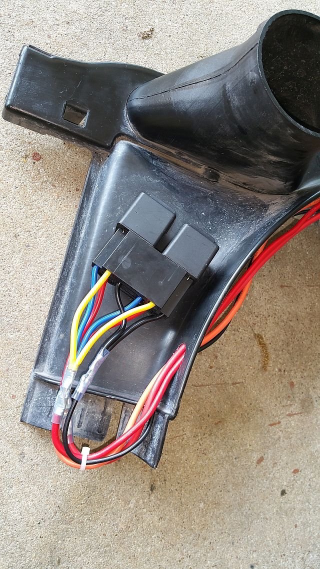
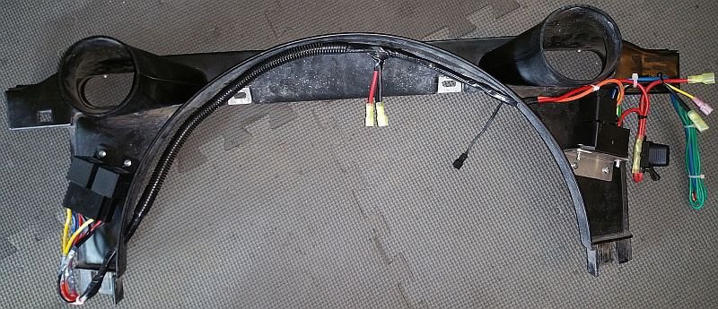
Here's a shot of how I rigged my wire harness. I wanted to get to it easily, and to be able to keep it fairly hidden, and to keep it dry, and ...well a bunch of things. so I integrated it into the shroud itself. I also realized that there's way more wires in there than ya need, so I cleaned all that mess up too. I put connectors on everything so I can pull the whole unit in just a few seconds.
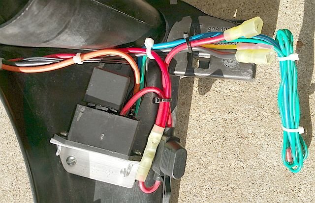
here's the drivers side module. I cleaned up the wires, and ran them over to the center for the fan power, and on across for the ground and controller connections.
what isn't in this picture is the yellow wire from the controller (ACC ON) that I ran back over with these wires, under the relays and fused it and connected it to the resistor inputs for the ACC ON signal. I did that after I took this shot.
Here's the connection to the main power (red wire). The ground goes down to a bolt where the smog pump filter was mounted. The green wire back there runs to the AC solenoid along that "other green wire". As I said, the yellow wire was there just for a test, but I eventually ran it back over to the other side. Everything has a plug connector as you can see.
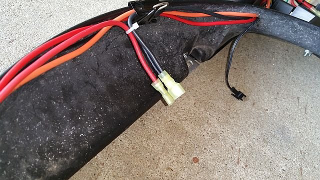
and the passenger side. Once again, I cleaned up the wires so all grounds go to a single connector, and all power goes through a single fuse and connector, the yellow wire as I said, was run back over to the other side after this picture. The green wire I put a connector on and ran to the AC air solenoid valve, and the blue (light) wire is unused in my application...currently) notice that the module is angled slightly...that's so my little screwdriver can get to the adjustment pot quick and easy on the fly.
the center has provisions for the fan (also on quick connectors) the ground for the fans is shared with the grounds for the aux relays. you can also see the connection for the probe type thermostat.
Now certainly I'm not gonna leave it all exposed like that. That's just so you folks can take a look.
In the end it looks like this. Two front bolts and unplug the connectors and it's out for service.
eh? eh? Heh, heh, heh! yeah!
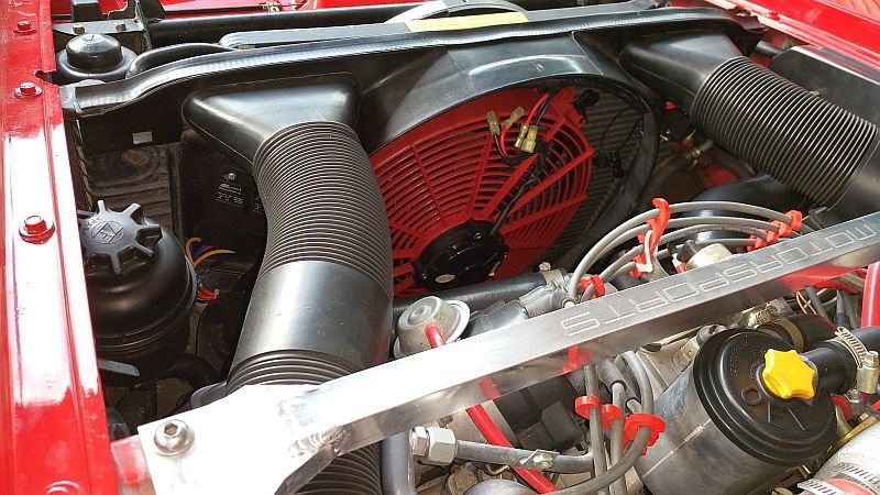
and it's well hidden, but accessable, and adjustable if I need to get a screwdriver to it.
...and that's it. After I plugged it all in of course. Adjusted the pot to bring the fan online just as the thermostat opens to keep it where it used to run, just below the upper white line.
Last edited by The Patman; May 17, 2015 at 10:23 AM.
Reason: I'm an idiot or maybe the "r" button isn't always working...could go either way.
Patman,
Nice job. I am very impressed with The FF Dynamics products. I have purchased 5 of their fans, and they are beautiful. The bearings seem very good, and the fans are very quiet and efficient.
Dave
Awesome, thanks, yeah, mine stalled for awhile too. Had Borla and a hi-flow added to mine so it was away fro 2 weeks. Just got it back. i'll look at what you did, just before i took it to have the exhaust, i actually sneaked the yellow/green into the passenger CE panel area and half-assed a spade connector on one of the un-used spots in the panel and put in a 16A fuse. it's functional but looks terrible. Wonder how people tap ito the CE panel in a good way, can't figure out a good way to bug on to it without looking like crap. Fan is grea though. Can't decide if i really need the green AC wire though(?) would think the pot and switched ign feed would turn it on fine without the AC hooked up, which seems to be the case. I'll take pics too, but like your idea, and keeping all the wires in the eng compartment.
Thanks for all the info on this fan setup. I have been going back and forth with re-oiling the clutch on the original belt fan or replacing the whole thing. I think I am going with this FF Dynamics setup as well. I will let you guys know how it goes.
9 Vehicles Porsche Helped Engineer that Aren't Porsches
Slideshow: Long before engineering consulting became trendy, Porsche was quietly helping other automakers build everything from supercars to economy hatchbacks.
9 Features and Characteristics That Only Porsche People Understand
Slideshow: Some brands build cars. Porsche builds traditions, obsessions, and a few habits that stopped making sense decades ago but somehow became part of the charm.
This Builder Is Turning Heads With Its Slantnose 911 Creation
Slideshow: A small Polish tuner has reimagined the Porsche 911 Slantnose for the modern era, blending 1980s nostalgia with widebody tuning culture and serious performance upgrades.
Porsche 911 GT3 Artisan Edition Pays Homage to Japanese Culture
Slideshow: Porsche has created a Japan-only 911 GT3 Artisan Edition that blends track-ready hardware with design cues inspired by traditional Japanese craftsmanship.
Porsche Reveals Coupe Variant of the Electric Cayenne With a Fresh Look
Slideshow: Porsche's latest electric Cayenne Coupe blends dramatic styling with supercar acceleration, turning the brand's midsize SUV into a 1,139-horsepower flagship.