

Updated Single Page Central Electric Panel Relay, Fuse & Plug Details (All Years)

 02-27-2014 | 05:40 PM
#122
Thread Starter
Electron Wrangler
Lifetime Rennlist
Member
Lifetime Rennlist
Member
Joined: Mar 2002
Posts: 13,442
Likes: 441
From: Phoenix AZ
Your car has a UK Dim-Dip Headlamp Relay installed - correct for model year in UK only...?
The dim part of the dim-dip is a separate module (I assume that you don't have that). Tell tale here is do the pods go up in position 1 of (0-2) of the HL switch - e.g. marker lights? do the Low beams come on?
On USA relay equipped cars the pods only go up in position 2, though they will stay up in position 1 after they go up - only going down in position 0.
Was the relay replaced at some time - or maybe this was a deliberate swap for some reason - I suspect it doesn't change the function very much without the dim(er) unit also installed.
Alan
02-27-2014 | 06:07 PM
#123
Addict
Rennlist Member
Rennlist Member
Joined: Jul 2001
Posts: 7,330
Likes: 110
From: Shawnee, KS, USA
I just went out to double check that XXIII-XXIV is really 928.618.107.01 and not 928.618.107.04. It's definitely .01.
Nope, no rear fog gear at all.
No, they don't. And no.
That's the behavior on my car.
I'm not aware of it (not while I had it, I'm almost positive); I've had the car since '99. Perhaps there was a replacement prior to that. I might be able to dig through the earlier records (although I'm not sure I have many, and I don't think they're complete).
It would be interesting to hear some other USA '90 people check in and report what they're seeing for relay XXIII-XXIV.
Nope, no rear fog gear at all.
Your car has a UK Dim-Dip Headlamp Relay installed - correct for model year in UK only...?
The dim part of the dim-dip is a separate module (I assume that you don't have that). Tell tale here is do the pods go up in position 1 of (0-2) of the HL switch - e.g. marker lights? do the Low beams come on?
The dim part of the dim-dip is a separate module (I assume that you don't have that). Tell tale here is do the pods go up in position 1 of (0-2) of the HL switch - e.g. marker lights? do the Low beams come on?
It would be interesting to hear some other USA '90 people check in and report what they're seeing for relay XXIII-XXIV.
03-02-2014 | 01:16 AM
#124

Advanced
Joined: Jan 2014
Posts: 86
Likes: 7
From: San Ramon CA
Alan, Reporting in on my 1981 USA 928, auto trans, no alarm. Its a 35K mile car, so I think most things are still untouched factory original. There is evidence of some tinkering with wires for the stereo but that's all. I was not able to verify function of these fuses, it was just a visual comparison. Here is what I found:
CE panel: 928.610.105.04
8A fuses in slots 7, 13 - not sure why, the two left hand spare fuses were missing...I think the PO just put them in these slots.
16A fuses in slots 19 (headlight motor) and 22 (fuel pump)
V relay= 111.953.227D
VI relay=928615.116.00
VII relay=431955535
XII relay=928.615.117.01
XV relay=928.618.113.00
XVI relay=928.615.119.00
CE Connector Plugs:
A=Yellow
B=Blue
C=Red
D=White
E=Black
F=Yellow
G=Blue
H=Red
J=White
K=Black
L=Yellow
M=Blue
N=Red
Y=empty
Z=empty
O=White
P=Black
Q=Yellow
R=empty
S=Red
T=White
U=Black
V=Yellow
W=Blue
X=empty
Last edited by Jeff Bowlsby; 03-07-2014 at 03:15 AM.
03-02-2014 | 06:02 PM
#125
Rennlist Member
Joined: Jul 2009
Posts: 2,558
Likes: 256
From: Gibsonia, PA
Alan, here's my review for the MY 85.
I compared your new chart with what I had. My charts that reside above the CE panel cover, 928 Specialist Fuse Relay Charts(I knew some of this is incorrect), PET6 printout and the Free Printable Relay Stickers from aircooler in this thread.
https://rennlist.com/forums/showthre...ferrerid=71405
Part# 928.610.105.09 confirmed
Left and Right side of my CE Panel. (Found a couple wrong fuse sizes in 5, 7 and 12 of my panel)
My Fuse/Relay chart from the panel cover.
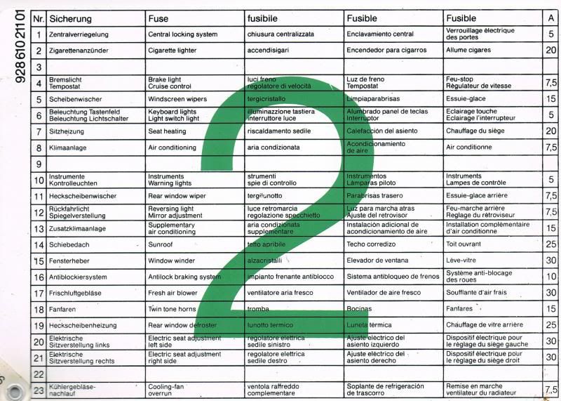
Fuse Chart - Everything checks out between all my info. except the following.
#9 shows nothing on my cover chart 2.
#10 shows "instruments, warning lights" on my cover chart 2
#24 I have "clock" written down in pen on one of my charts. I don't know for sure if this is correct or not.
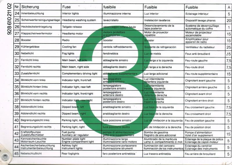
#44 shows "Ashtray light" on my cover chart 3
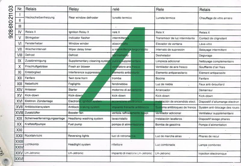
Relay Chart - Everything checks out between all my info. except the following.
Relay 5 - 111 953 227 D at PET6 and Sticker Chart - Also, PET6 shows 928 615 131 00 Flasher, Trailer Coupling.
Relay 6 - PET6 and Sticker Chart show 00 in lieu of 02.
Relay 7 - Two no.s listed on your chart show up in my info. Are both necessary?
Relay 8 - My relay is also a tester. I didn't confirm that 928.615.203.00 is a tester. Is it?
Relay 15 - Since I have 5 speed this is not used.
Relay 17 - My info shows this as ABS 928.615.124.01 I don't have this option on my car so it's not used.
Relay 19 - Should be XIX not IXX
Relay 22 - Bridge 928.615.125.00 if Manual - Be clearer in description?
Relay Socket Terminal ID
Here's mine (sorry I couldn't get a clearer shot)
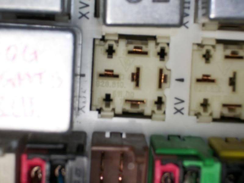
Part No. 928.610.511.00 (I think 610 and 511 are correct. It is hard to distinguish between a 5 and 6 in the low lite of the foot well)
Slot orientation and numbers. Left to Right, Top to Bottom.
Vert(1)
Horiz(2)
Vert(8)
Horiz(3)
Vert(4)
Vert(5)
Vert(6)
Horiz(7)
Vert(9)
That's it. Let me know if I need to do more. I hope I helped.
I compared your new chart with what I had. My charts that reside above the CE panel cover, 928 Specialist Fuse Relay Charts(I knew some of this is incorrect), PET6 printout and the Free Printable Relay Stickers from aircooler in this thread.
https://rennlist.com/forums/showthre...ferrerid=71405
Part# 928.610.105.09 confirmed

Left and Right side of my CE Panel. (Found a couple wrong fuse sizes in 5, 7 and 12 of my panel)


My Fuse/Relay chart from the panel cover.


Fuse Chart - Everything checks out between all my info. except the following.
#9 shows nothing on my cover chart 2.
#10 shows "instruments, warning lights" on my cover chart 2
#24 I have "clock" written down in pen on one of my charts. I don't know for sure if this is correct or not.
#44 shows "Ashtray light" on my cover chart 3
Relay Chart - Everything checks out between all my info. except the following.
Relay 5 - 111 953 227 D at PET6 and Sticker Chart - Also, PET6 shows 928 615 131 00 Flasher, Trailer Coupling.
Relay 6 - PET6 and Sticker Chart show 00 in lieu of 02.
Relay 7 - Two no.s listed on your chart show up in my info. Are both necessary?
Relay 8 - My relay is also a tester. I didn't confirm that 928.615.203.00 is a tester. Is it?
Relay 15 - Since I have 5 speed this is not used.
Relay 17 - My info shows this as ABS 928.615.124.01 I don't have this option on my car so it's not used.
Relay 19 - Should be XIX not IXX
Relay 22 - Bridge 928.615.125.00 if Manual - Be clearer in description?
Relay Socket Terminal ID
Here's mine (sorry I couldn't get a clearer shot)

Part No. 928.610.511.00 (I think 610 and 511 are correct. It is hard to distinguish between a 5 and 6 in the low lite of the foot well)
Slot orientation and numbers. Left to Right, Top to Bottom.
Vert(1)
Horiz(2)
Vert(8)
Horiz(3)
Vert(4)
Vert(5)
Vert(6)
Horiz(7)
Vert(9)
That's it. Let me know if I need to do more. I hope I helped.
Last edited by WyattsRide; 03-02-2014 at 06:47 PM. Reason: Added Socket info.
03-03-2014 | 01:57 AM
#126
Rennlist Member
Joined: Apr 2009
Posts: 57
Likes: 2
From: Dallas, TX USA
Alan (& Jeff),
I have 2 USA 1981 central electric panels, both with part numbers 928.610.105.04. One is in the car, the other I purchased off an internet auction site. There are differences between these units & the documentation that I would like to highlight.
Fuse 7 is brake lights and cruise control. Brake lights are not on fuse 10 as shown on your diagram and in my owner's manual. See Current Flow Diagram V for details (links to XI/8 for cruse control power.)
Fuse 10 is not correctly shown in the Current Flow Diagrams. It is shown as unused on Diagram VI but actually sits between the 15 Bus and terminal H7 on Diagram X. Terminal H7 looks to be power for the alternator light, mileage counter, and Central Warning. (It is listed as brake / cruise control in my manual.) (This information comes from the spare panel - I will probably pull the installed panel next weekend - I will verify this information on that panel.)
I have one known difference between my two panels: The spare panel puts Fuse 13 between the 15 Bus and terminal O6. Terminal O6 looks to provide power for the ignition system - the connection is shown on Current Flow Diagram I. This fuse is not present in the panel that I have installed in my car, and I have not pulled that panel to see what (if any) connections are there.
On Alan's diagram, the description for Fuse 22 includes WUR. I don't think that the AFC cars have a WUR.
I thank you for your effort in putting these diagrams together - I am looking forward to laminating the finished product to the wooden plank that covers the CE panel.
I enumerated all fuse connections (terminals on both sides of each fuse and diagram pages showing the fuse) within my spare panel and I can supply further details if you find this useful.
I actually enjoy figuring out the old style Current Flow diagrams - I find it more entertaining than the Oscars!
Update:
The original panel from my 1981 US 5-speed uses Fuse 7 for brake light and cruise control. Fuses 10 and 13 are unused and are not connected on the output side. The connections to terminals H7 and O6 and are direct to the 15 Bus. This makes my car's original panel match the US 1981 Current Flow Diagrams exactly. BTW: The panel in my car has a date code of 8.5.81, the date code for the spare panel (that uses fuses 10 & 13) is 21.1.81. The build date for my car is 5.81, the VIN is WP0JA0926BS821505.
Please correct the 1981 panel diagram to (at least) show Fuse 7 as brake light and cruise control. I have no idea how to mark Fuses 10 and 13, as they appear to be used on some panels and not on others.
Last edited by qdac; 03-10-2014 at 12:26 AM. Reason: Update
 03-05-2014 | 04:17 AM
#128
Advanced
Joined: May 2006
Posts: 79
Likes: 2
From: Sonoma, CA
Reporting back for my 1987.
My VIN WP0JB0921HS861500 02/87 prod.
CE Panel 928.610.105.14
I checked the CE panel card, WSM and Technical Specifications book.
The CE panel card, WSM and tech spec book are all the same for fuses and relays.
Differences noted:
Fuse 9: Blank (no listing for phone)
Fuse 24: Add diagnostic connector
All relays listed correctly.
Thanks again for all your work!
Paul
03-09-2014 | 05:22 PM
#131
Rennlist Member
Joined: Jun 2011
Posts: 643
Likes: 15
From: Helsinki, Finland
Reporting back for ROW MY 1994. My car was registered for the German road on 20th April 1994, and having found one relay on my CE panel with a production date stamp of 01.02.94 (and it being a VW relay, 111 953 227D, most likely therefore means a date of 1st February 1994) must therefore logical mean that it was build anywhere between February - April 1994.
I compared the CE panel card + WSM with regards to the electrical schematics for MY 1994 (between which I did not find any faults) with your "CE Fuse Relay 1992-1995.pdf" file.
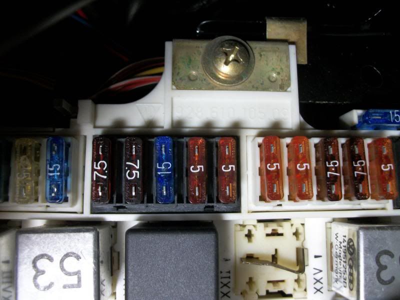
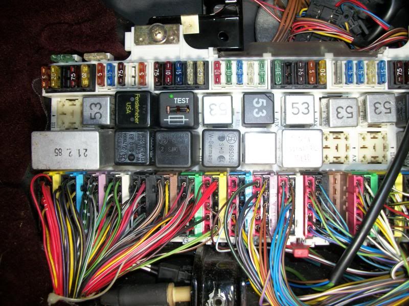
CE panel is 928.610.105.24 , as can be seen from the following photo:
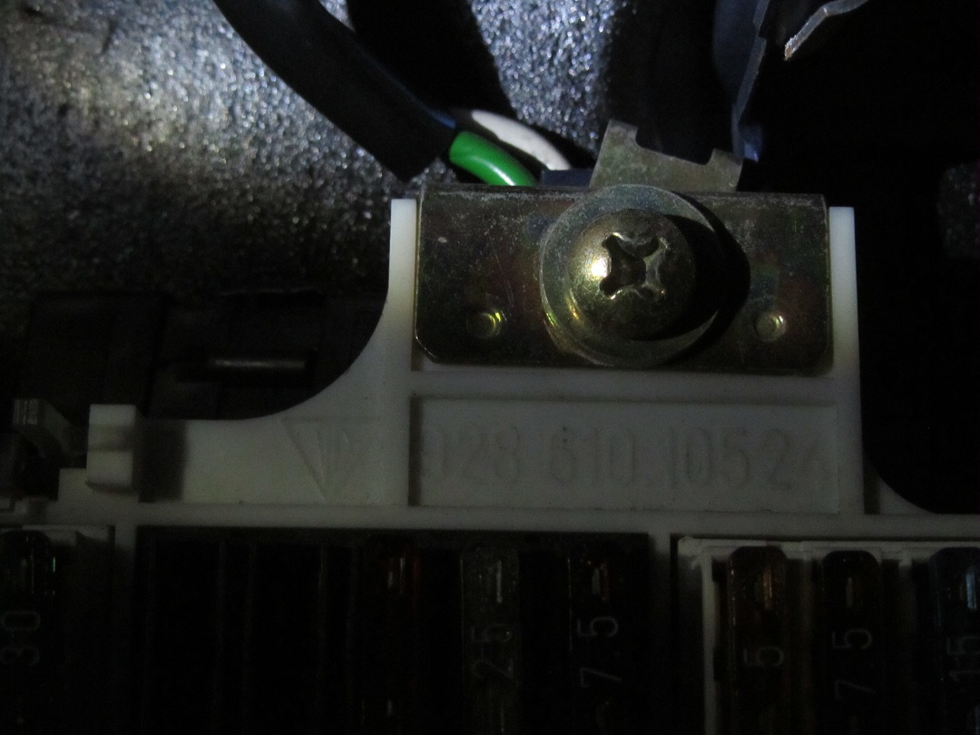
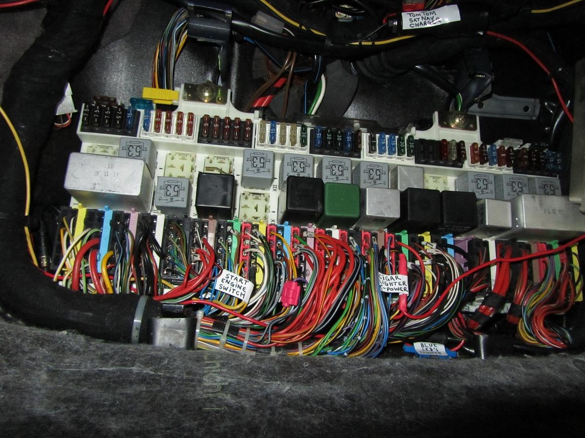
CE panel, this photo is from 1st May 2011, before I started to do any major relay and fuses changes. The only fuse change on this particular picture when compared with factory is that I had already changed fuse 33 (cigarette lighter fuse) from 25A to 10A (as I had removed the cigarette lighter and put something else in it's place):
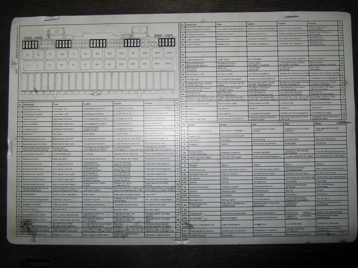
CE panel chard:
Differences as I noted when compared with your "CE Fuse Relay 1992-1995.pdf" file:
- Relay VIII: on my CE panel this is: a short between pin '85' to '86' (note: fog light relay 141.951.253.B. is for USA and Japan only).
Additional note on 16th March 2014 (see also Alan's post #132 and my post #144): WRONG info, the correct info being that this is a short between pin '30' and '87', those being the relay main switch pin's on this one (while pin '86' and '87' are the relay coil pin's).
- Relay XIII: on my CE panel this (was original, I later changed this for a local Finnish LED relay flasher) is: 111 953 227D.
- Relay XXII: on my CE panel this is: 141.951.253.B.
Alan: thanks a lot for doing all this work for the greater good of the 928 community!
I compared the CE panel card + WSM with regards to the electrical schematics for MY 1994 (between which I did not find any faults) with your "CE Fuse Relay 1992-1995.pdf" file.
CE panel is 928.610.105.24 , as can be seen from the following photo:
CE panel, this photo is from 1st May 2011, before I started to do any major relay and fuses changes. The only fuse change on this particular picture when compared with factory is that I had already changed fuse 33 (cigarette lighter fuse) from 25A to 10A (as I had removed the cigarette lighter and put something else in it's place):
CE panel chard:
Differences as I noted when compared with your "CE Fuse Relay 1992-1995.pdf" file:
- Relay VIII: on my CE panel this is: a short between pin '85' to '86' (note: fog light relay 141.951.253.B. is for USA and Japan only).
Additional note on 16th March 2014 (see also Alan's post #132 and my post #144): WRONG info, the correct info being that this is a short between pin '30' and '87', those being the relay main switch pin's on this one (while pin '86' and '87' are the relay coil pin's).
- Relay XIII: on my CE panel this (was original, I later changed this for a local Finnish LED relay flasher) is: 111 953 227D.
- Relay XXII: on my CE panel this is: 141.951.253.B.
Alan: thanks a lot for doing all this work for the greater good of the 928 community!
Last edited by Arnoud; 03-16-2014 at 07:57 AM.
03-10-2014 | 07:53 PM
#132
Thread Starter
Electron Wrangler
Lifetime Rennlist
Member
Lifetime Rennlist
Member
Joined: Mar 2002
Posts: 13,442
Likes: 441
From: Phoenix AZ
Reporting back for ROW MY 1994.
Differences as I noted when compared with your "CE Fuse Relay 1992-1995.pdf" file:
- Relay VIII: on my CE panel this is: a short between pin '85' to '86' (note: fog light relay 141.951.253.B. is for USA and Japan only).
- Relay XIII: on my CE panel this (was original, I later changed this for a local Finnish LED relay flasher) is: 111 953 227D.
- Relay XXII: on my CE panel this is: 141.951.253.B.
Relay VIII - I think its actually a bridge between 30-87 (all ROW GTS + '91 S4 should have this)
Relay XIII - yes I have already added the original flasher ID (same as you noted - all years)
Relay XXII - 928.615.203.00 & 141.951.253.B are functionally equivalent (first additionally has the fuse tester feature - it can be used anywhere a 53B is used (and V-V). My car did not have a fuse tester when I got it (so like yours) wasn't sure if it was never installed or had been replaced ... so maybe it was more Porsche economizing in late production...?
Alan
03-10-2014 | 09:14 PM
#133
Thread Starter
Electron Wrangler
Lifetime Rennlist
Member
Lifetime Rennlist
Member
Joined: Mar 2002
Posts: 13,442
Likes: 441
From: Phoenix AZ
Alan (& Jeff),
I have 2 USA 1981 central electric panels, both with part numbers 928.610.105.04. One is in the car, the other I purchased off an internet auction site. There are differences between these units & the documentation that I would like to highlight.
Fuse 7 is brake lights and cruise control. Brake lights are not on fuse 10 as shown on your diagram and in my owner's manual. See Current Flow Diagram V for details (links to XI/8 for cruse control power.)
Fuse 10 is not correctly shown in the Current Flow Diagrams. It is shown as unused on Diagram VI but actually sits between the 15 Bus and terminal H7 on Diagram X. Terminal H7 looks to be power for the alternator light, mileage counter, and Central Warning. (It is listed as brake / cruise control in my manual.) (This information comes from the spare panel - I will probably pull the installed panel next weekend - I will verify this information on that panel.)
I have one known difference between my two panels: The spare panel puts Fuse 13 between the 15 Bus and terminal O6. Terminal O6 looks to provide power for the ignition system - the connection is shown on Current Flow Diagram I. This fuse is not present in the panel that I have installed in my car, and I have not pulled that panel to see what (if any) connections are there.
On Alan's diagram, the description for Fuse 22 includes WUR. I don't think that the AFC cars have a WUR.
I thank you for your effort in putting these diagrams together - I am looking forward to laminating the finished product to the wooden plank that covers the CE panel.
I enumerated all fuse connections (terminals on both sides of each fuse and diagram pages showing the fuse) within my spare panel and I can supply further details if you find this useful.
I actually enjoy figuring out the old style Current Flow diagrams - I find it more entertaining than the Oscars!
Update:
The original panel from my 1981 US 5-speed uses Fuse 7 for brake light and cruise control. Fuses 10 and 13 are unused and are not connected on the output side. The connections to terminals H7 and O6 and are direct to the 15 Bus. This makes my car's original panel match the US 1981 Current Flow Diagrams exactly. BTW: The panel in my car has a date code of 8.5.81, the date code for the spare panel (that uses fuses 10 & 13) is 21.1.81. The build date for my car is 5.81, the VIN is WP0JA0926BS821505.
Please correct the 1981 panel diagram to (at least) show Fuse 7 as brake light and cruise control. I have no idea how to mark Fuses 10 and 13, as they appear to be used on some panels and not on others.
I have 2 USA 1981 central electric panels, both with part numbers 928.610.105.04. One is in the car, the other I purchased off an internet auction site. There are differences between these units & the documentation that I would like to highlight.
Fuse 7 is brake lights and cruise control. Brake lights are not on fuse 10 as shown on your diagram and in my owner's manual. See Current Flow Diagram V for details (links to XI/8 for cruse control power.)
Fuse 10 is not correctly shown in the Current Flow Diagrams. It is shown as unused on Diagram VI but actually sits between the 15 Bus and terminal H7 on Diagram X. Terminal H7 looks to be power for the alternator light, mileage counter, and Central Warning. (It is listed as brake / cruise control in my manual.) (This information comes from the spare panel - I will probably pull the installed panel next weekend - I will verify this information on that panel.)
I have one known difference between my two panels: The spare panel puts Fuse 13 between the 15 Bus and terminal O6. Terminal O6 looks to provide power for the ignition system - the connection is shown on Current Flow Diagram I. This fuse is not present in the panel that I have installed in my car, and I have not pulled that panel to see what (if any) connections are there.
On Alan's diagram, the description for Fuse 22 includes WUR. I don't think that the AFC cars have a WUR.
I thank you for your effort in putting these diagrams together - I am looking forward to laminating the finished product to the wooden plank that covers the CE panel.
I enumerated all fuse connections (terminals on both sides of each fuse and diagram pages showing the fuse) within my spare panel and I can supply further details if you find this useful.
I actually enjoy figuring out the old style Current Flow diagrams - I find it more entertaining than the Oscars!
Update:
The original panel from my 1981 US 5-speed uses Fuse 7 for brake light and cruise control. Fuses 10 and 13 are unused and are not connected on the output side. The connections to terminals H7 and O6 and are direct to the 15 Bus. This makes my car's original panel match the US 1981 Current Flow Diagrams exactly. BTW: The panel in my car has a date code of 8.5.81, the date code for the spare panel (that uses fuses 10 & 13) is 21.1.81. The build date for my car is 5.81, the VIN is WP0JA0926BS821505.
Please correct the 1981 panel diagram to (at least) show Fuse 7 as brake light and cruise control. I have no idea how to mark Fuses 10 and 13, as they appear to be used on some panels and not on others.
Alan
Last edited by Alan; 03-10-2014 at 10:10 PM.
03-12-2014 | 12:39 PM
#134
Rennlist Member
Joined: Apr 2009
Posts: 57
Likes: 2
From: Dallas, TX USA
Alan,
I am attaching the date code (top) and back photos for both the installed and spare panels. The installed panel is shown in the first two photos, the spare in the second two photos.
Note that my installed panel has one hack. A PO had cut the power for the aux cooling fan and run it to a radio amplifier. I fixed this long ago. There do not appear to be any hacks in the spare panel.
03-12-2014 | 01:09 PM
#135
Thread Starter
Electron Wrangler
Lifetime Rennlist
Member
Lifetime Rennlist
Member
Joined: Mar 2002
Posts: 13,442
Likes: 441
From: Phoenix AZ
David - can you take some photos of your spare panel that show the 'busbar' detail in the locations below - this is where multiple fuse inputs are ganged together - similar in concept to the large 30 feeder busbar in the middle (but fed by connector wire). Oh and can you see any other linked fuse input sides (except by wires/terminals) e.g. pairs or other busses?
Thanks - Alan
Thanks - Alan
Last edited by Alan; 03-12-2014 at 01:40 PM.