When you click on links to various merchants on this site and make a purchase, this can result in this site earning a commission. Affiliate programs and affiliations include, but are not limited to, the eBay Partner Network.
There is now 3 additional flutes planned on the top of the guards. I have executed one of the three but these are not easy to make, well not easy for me to make anyway. All are designed to be functional and relieve any high pressures plus duct out hot air. The engine for a naturally aspirated 2 valve engine will be quite powerful and produce a lot of heat. Since the aero will be important some of the bottom of the car is closed in. As such getting rid of hot air will need to be very well planned. Once I get back to working on the car progress will hopefully speed up. There is many custom pieces, too many in fact and I will have to rationalise the project somewhat. So a small update.
What has been happening is the block has been Nicasil coated in Australia but it has not been honed as of typing but it is in the honing machine ready to go. So barring a calamity I will have my bored and coated block. That has taken 1 year! As soon as I get that block back I am getting the crankshaft made to my specification. It will either be 96 or 101 mm stroke this will depend a little on the coating in the bore also the revs and fuel being used. I need to make sure the bores are coated everywhere where the piston will run. Im talking right down the bottom where the crankshaft web is. Some people may question why that is the case but we didn't coat the block in a full immersion method as used by Millennium. The block will still be shiny on the outside. Not that that is a big deal but we don't have the same facilities here.
The two major billet pieces are the dry sump oil pan and associated own made oil pump and billet cam boxes. All of these pieces are designed from scratch and are the best technology you can put into an engine. I anticipate 16 mm valve lift on the intake side. I will use the radius dlc coated lifters which are just 30 grams and hydraulic in operation. The valve train limit would be around 8,500 rpm but if I go with the longer stroke, it can't rev that high anyway. More likely it will be 96 mm with the longer 6.2" rods. You might question how will that be done? Well the custom cam boxes will use cam bearing caps like the 4V except more sturdy, like a girdle and we are raising the cam boxes so that a bigger spring can be used as well as high porting the heads. These heads will flow better than a standard or slightly modified 4V head. So the boxes are raised and then you need extra belt length. You get that by doing away with the factory oil pump.
The dry sump does away with the factory oil pump, the pump will do pressure and suction and has 160 mm in total sections using 5 vacuum stages and 1 pressure stage. Oil pressure will be reduced along with reduced oil volume due to tighter clearances and better components. The pump will also have a oil air separator made by Auto Verdi, the pump is part mine and part Auto Verdi. The Auto Verdi separator is simply the best in the business with close to 100% efficiency. The pump won't get in the way of any of the accessories, it is a very big pump that will pull a big vacuum.
I will be getting onto the cylinder heads soon, there has been another delay, we were using the workshops cylinder head fixtures which we will now need to make ourselves. What we are doing is moving the valve locations to best unshroud the valves and maximise their size. Inlet valve will be at least 2.10" in size. I won't go any further right now but I would hope the machinist will finish the jobs left over from earlier in the year and I will post pics of them.
Small update, more plans have been formulated and I suppose we are at the big money stage. It�s a bit scary really as my money well is sorta dry.🙄 I have dealt with our house repairs which took priority, they were a big job and I�m glad that�s behind me now. However there is no time to waste as there has already been too many delays regarding suppliers. I hope my machinist works fast, I know he is also keen to get things happening. In the next month I hope to get back two blocks that have been Nicasil coated (but not honed) and when I get the block honed by another supplier I can order the crank as I want to correctly set the piston to deck height. That crank will be around 91 mm in stroke and use modified mains and rod journals. This engine will be about 6 litres and uses an oval port 2 V head with ITBs. That cylinder head is getting a massive amount of work. The chambers have been welded up and the head will need to be checked and straightened and then re-heat treated. The head is getting the valves moved to optimise the use of the 103 mm bore. The chamber is getting reshaped for better flow and better combustion via better quench. That�s a big job right there.
The other work has been on the 4 V head, this is the VarioCam heads. I choose these heads so long ago it�s a bit embarrassing, I also wasn�t aware at the time that the 944 S2 heads were similar (probably identical) in port size. These bigger ports are required for a big high revving engine. The S2 engine uses the 928 chain tensioners whereas the 968 heads use a dedicated purpose designed tensioner and given the 968 was a 4 cylinder I have to design or make work a tensioner for the cylinders 5-8. This has been done😎. I am actually modifying both tensioners.
The variocam system uses uses one less tooth on the cams, 17 vs 18. Given I have to make custom cams it doesn�t matter if I make them with 17 or 18 teeth. The reason for the use of the variocam in this application is that basically I am somewhat trapped with it but I am hoping it will help the engine run smoother on the street when the car is just cruising. Each cam is made from 4 unique pieces. This is made up a front cam section, the adjustable gear section and the rear cam section. The cams prior to grinding will centre bored and leave approximately a 2.5 mm wall thickness and this core will be filled with a titanium precision rod. This will be interference in certain locations.
Just for clarification, the intake valves are Ti, and the exhaust is inconel both using 6 mm stems. Both valves are very large and this may need to be adjusted. The inclination angle needs to be changed and the valves pushed apart. The valves will probably end up around 43 mm and 37 mm. This is a bit more conservative as there might be issues with too much material removel. The sleeves are being drawn now, the unfinished bore will be around 108 mm and the material is a premium cast iron that is used in the Top Fueler engines. This is a very hard material which is critical to long bore life. Once the valves are fitted I can cast the combustion chamber and get the pistons ordered. My thoughts are either JE or CP. They may need to be billet because of their size. This is not optimum.
Nice work. Just a heads up. I with multi piece cams years ago and during the initial startup the gears were sheared off the camshafts. I had to start over with solid billet non adjustable cams. This is when I had modified the 968 variocam to work on the 928 heads. It probably would have been better to use 968 heads and ITB's....
Nice work. Just a heads up. I with multi piece cams years ago and during the initial startup the gears were sheared off the camshafts. I had to start over with solid billet non adjustable cams. This is when I had modified the 968 variocam to work on the 928 heads. It probably would have been better to use 968 heads and ITB's....
i had forgotten about that trouble you had, it came back to me the moment you mentioned it, I would have thought you would have had trouble on the exhaust cam? I say that because it has the higher loads. That cam will not be adjustable, I was intending on using 4 hardened dowls that would go through the centre sprocket structure, note, this is not intended to be just a sprocket, it is a part that via interference will be mounted on a shaft. The ends of the cams the centre of the cams will be interference. Not massively high interference but enough to assist in a anti rotation measure. The other anti rotation anti shearing method I intend to employ is where the camshaft pieces meets the sprocket. Both ends of the camshaft will be tightened towards this sprocket. The sprocket having a recess it is pushed into.
On the intake side, it is different regarding the dowling, the dowls will be drilled to allow some adjustability, I was thinking just 2 dowls would do it as there is half the loads as this is the driven cam. When we put this into CAD I will see how much room we have to play with. What I wanted was to have enough adjustment to adjust out the Variocam so if I decided against using it, I would be able to set up the cams with the desired lobe separation angle. I was also going to try and have around 3 degrees to fine tune the LSA.
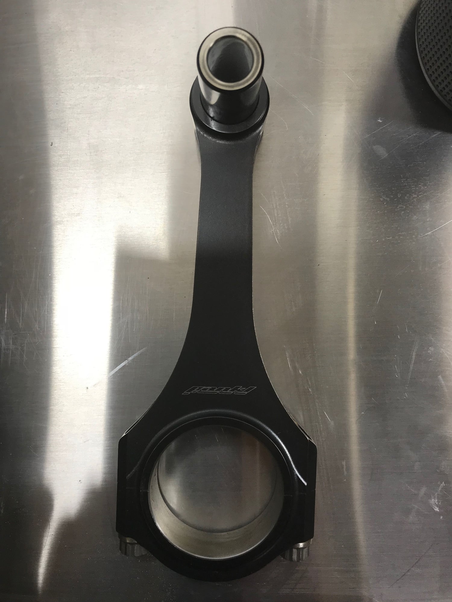
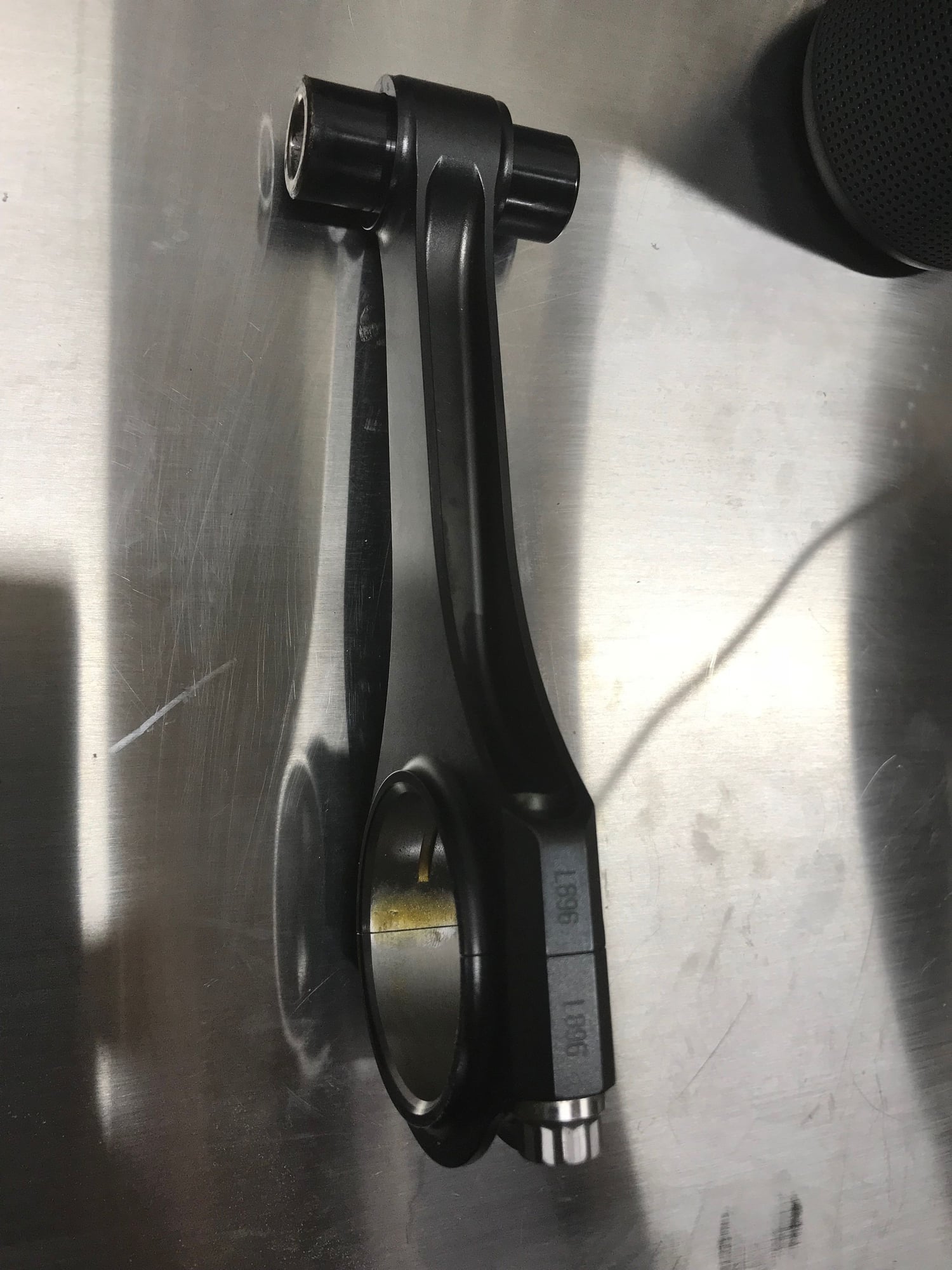
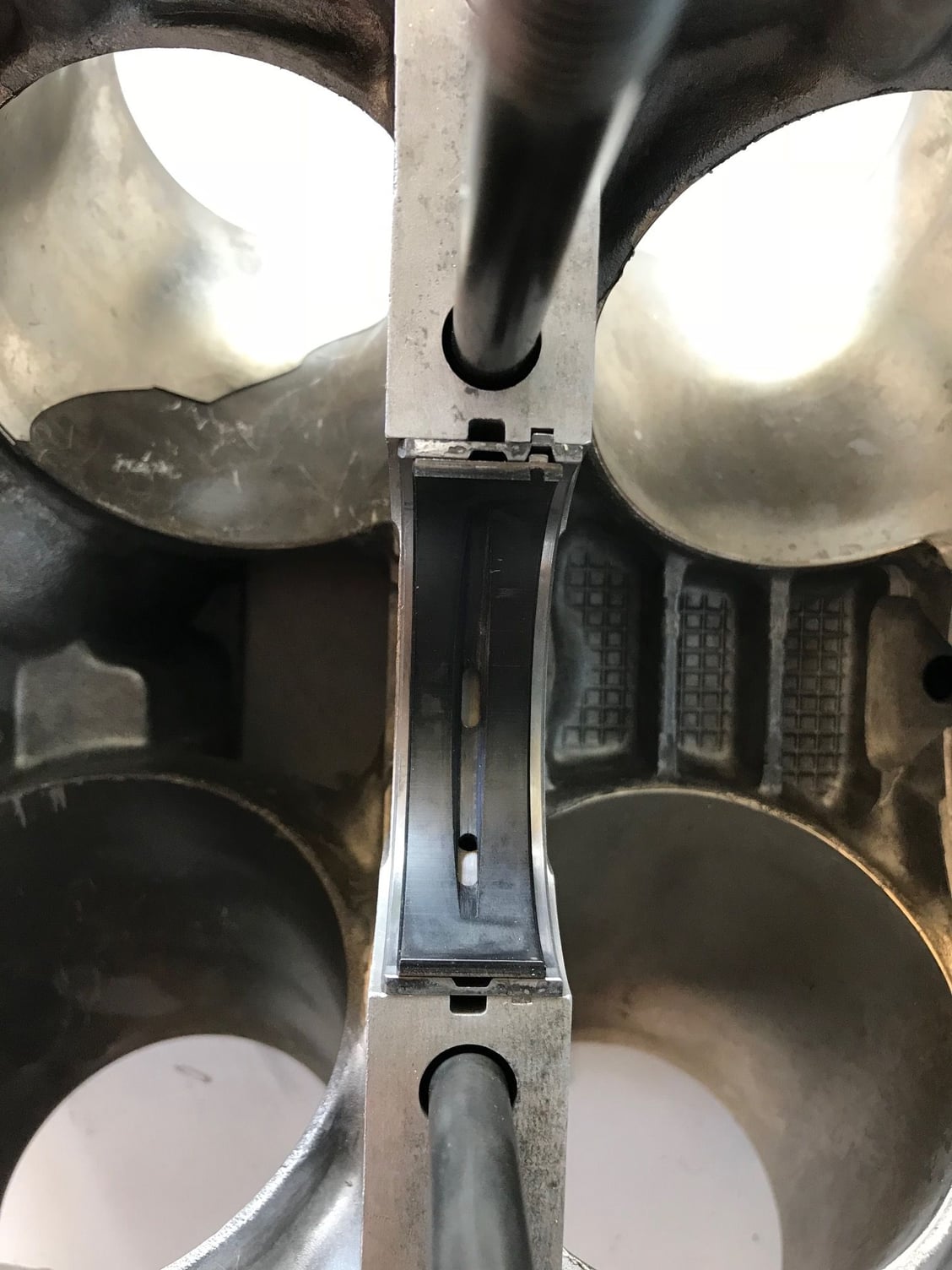
Well its been busy, I have selected the rod pin combo, it ended being a 6" rod with a 22 mm pin that is 57.785 mm long. The rod is 532 grams and has forced pin oiling, the pin 108 grams 0.170" wall thickness . I decided to go with the shorter rod with this engine due to the fact that both the 6" and 6.2" rods weigh the same due to Nascar rules, the rods are from a Nascar engine. So the reasoning is the thickest strongest rod possible. The same sized rod is used (Carrillo Brand) in the dirt engines 410 CI with the same stroke 3.75". Incidentally it they use the same sized or smaller pin with a comp ratio in excess of 14 to 1. The dirt engine builders set their redline at 9,000 rpm and when Nascar had no limits on RPM the same rods with a lesser stroke (Around 3.25") saw over 11,000 rpm.
Pankl Rod
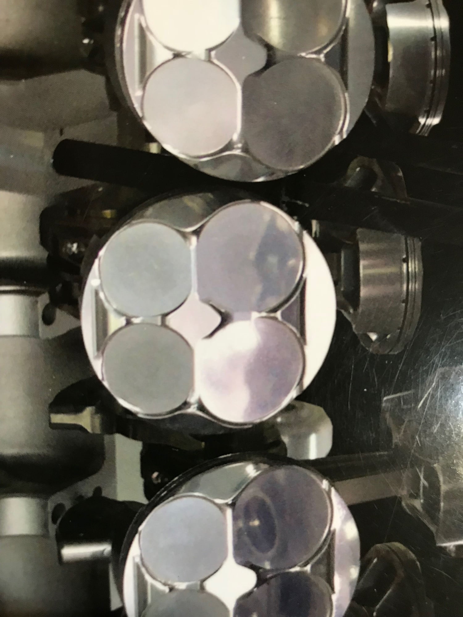
JE DLC pin 64C material
The other reason for the 6" rod is the need for considerable piston cutouts. There probably from my calculations that there will be no dish in the piston, the cutouts alone should be enough to create the volume that is need to obtain the desired compression
The cam profile will be pretty radical thanks to a lightweight radial tappets.
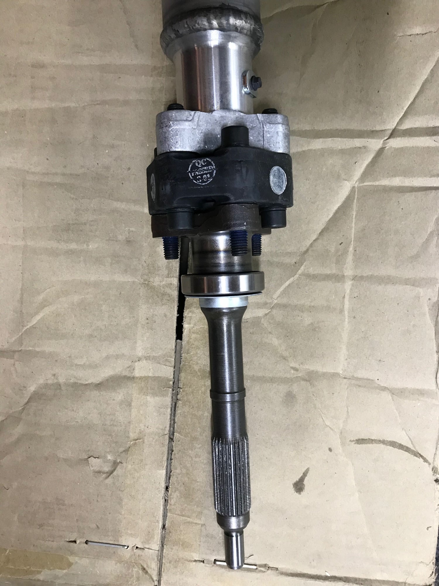
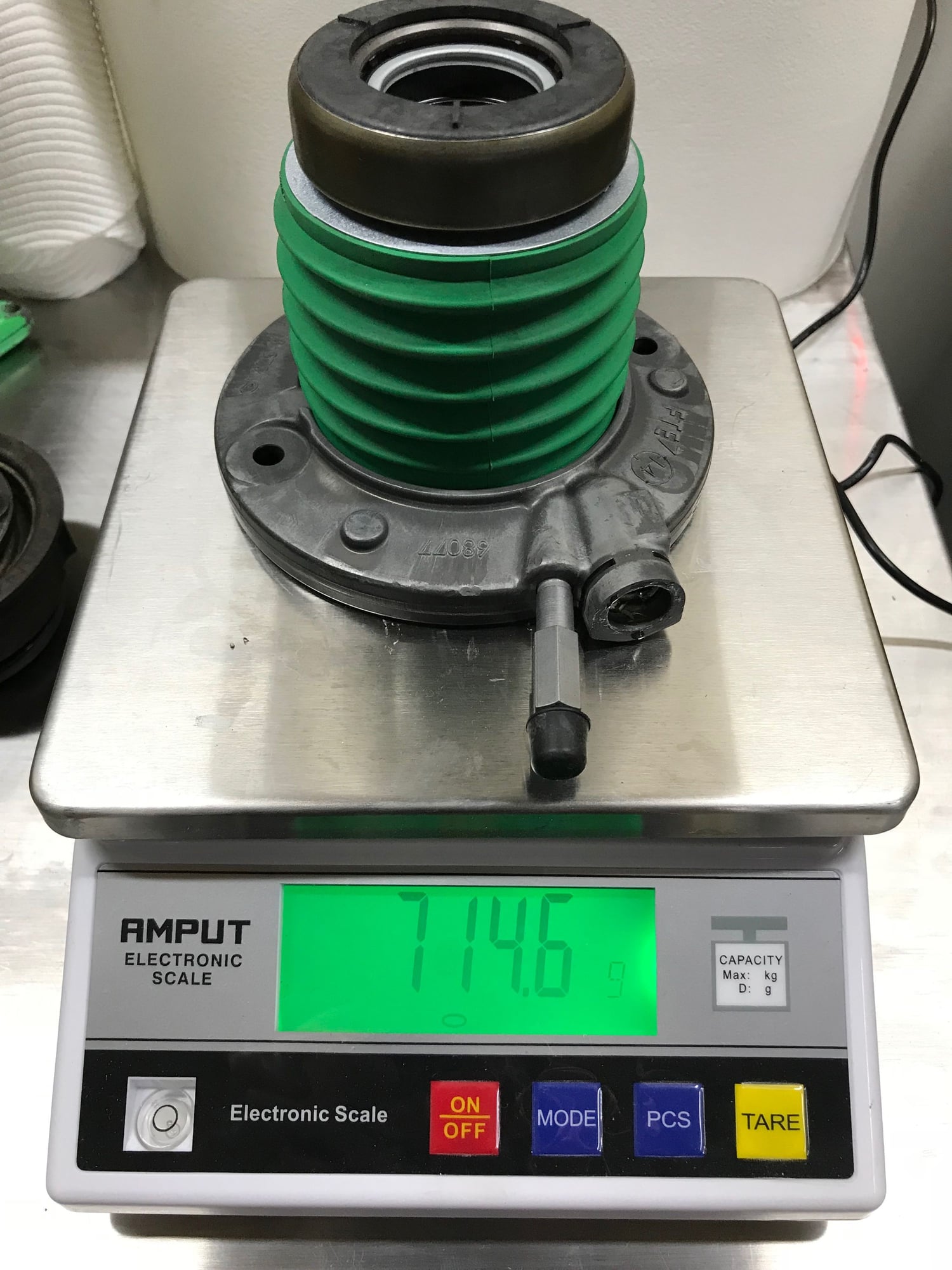
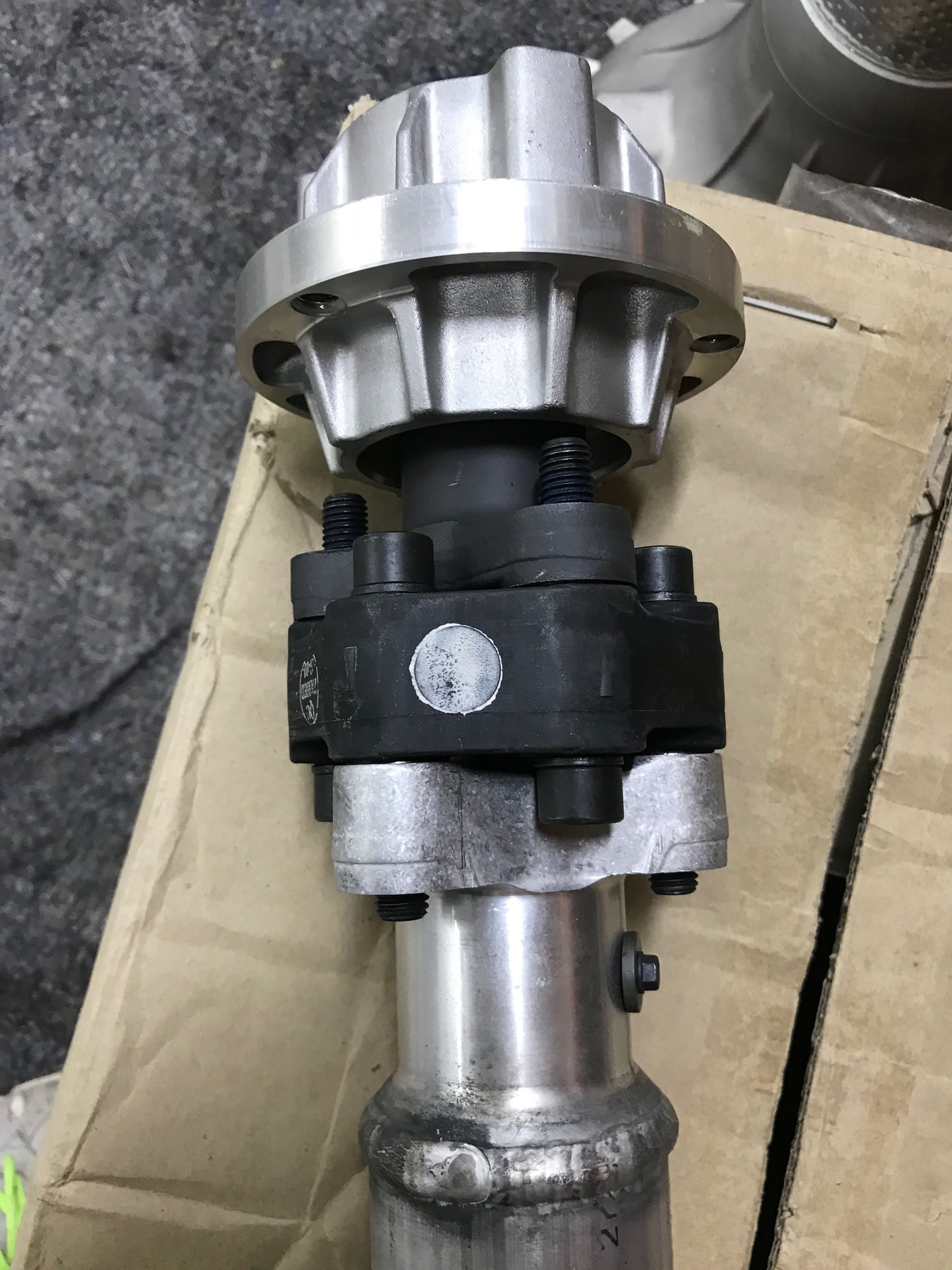
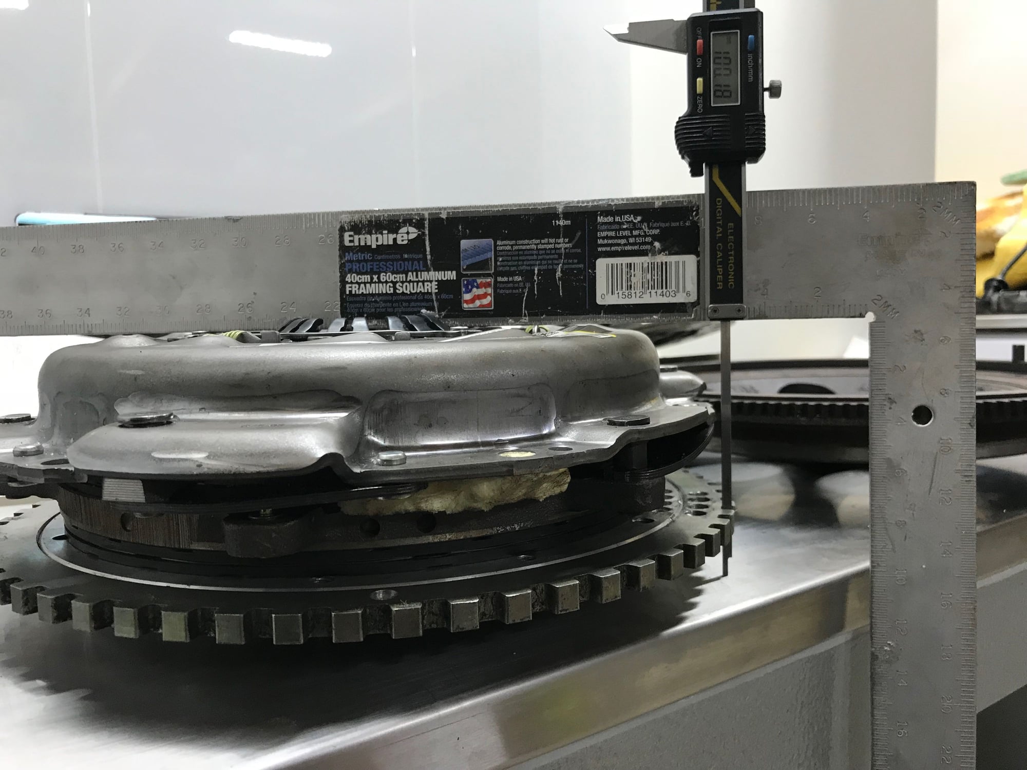
O.K potentially an interesting finding, I am planning to convert to to use the Corvette C7 Z06 clutch and driveshaft. I will make the torque tube and hopefully use my modified billet shifter in an effort to strengthen the drivetrain and make the shift more precise. To explain the photos, the input shaft on the Corvette is a separate piece from the driveshaft and it doesn't work in the same fashion as the sliding coupling on the 928. In a high power output application I don't think the coupling is the best idea. The spigot part that fits the bearing in the back of the flywheel is the same diameter. The clutch splines are considerably larger in diameter.
Corvette C7 Torque Tube Clutch Shaft
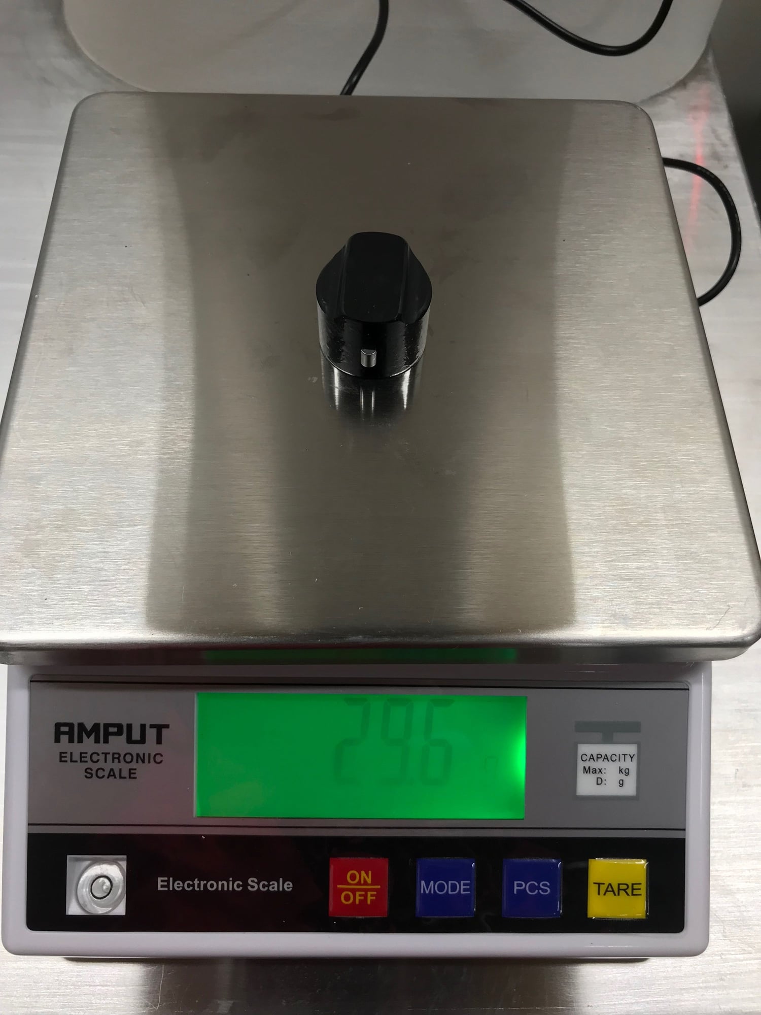
The total weight should work out about the same. The Corvette does away with the cast iron arm and cast iron slave cylinder. The throwout bearing weighs the same despite the Corvette's throwout bearing incorporating the hydraulic circuit to operate the clutch.
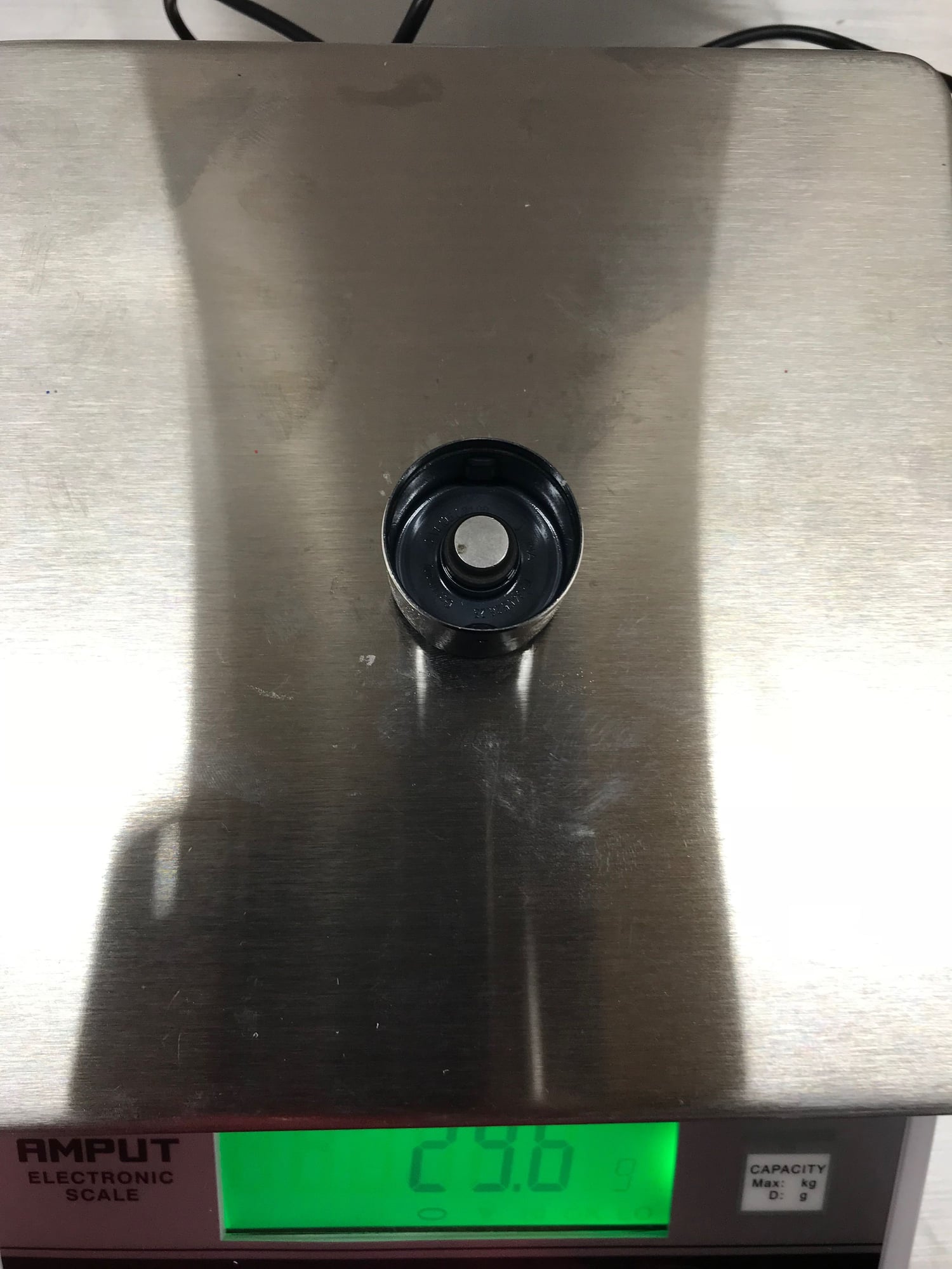
Porsche bearing
Corvette C7 bearing
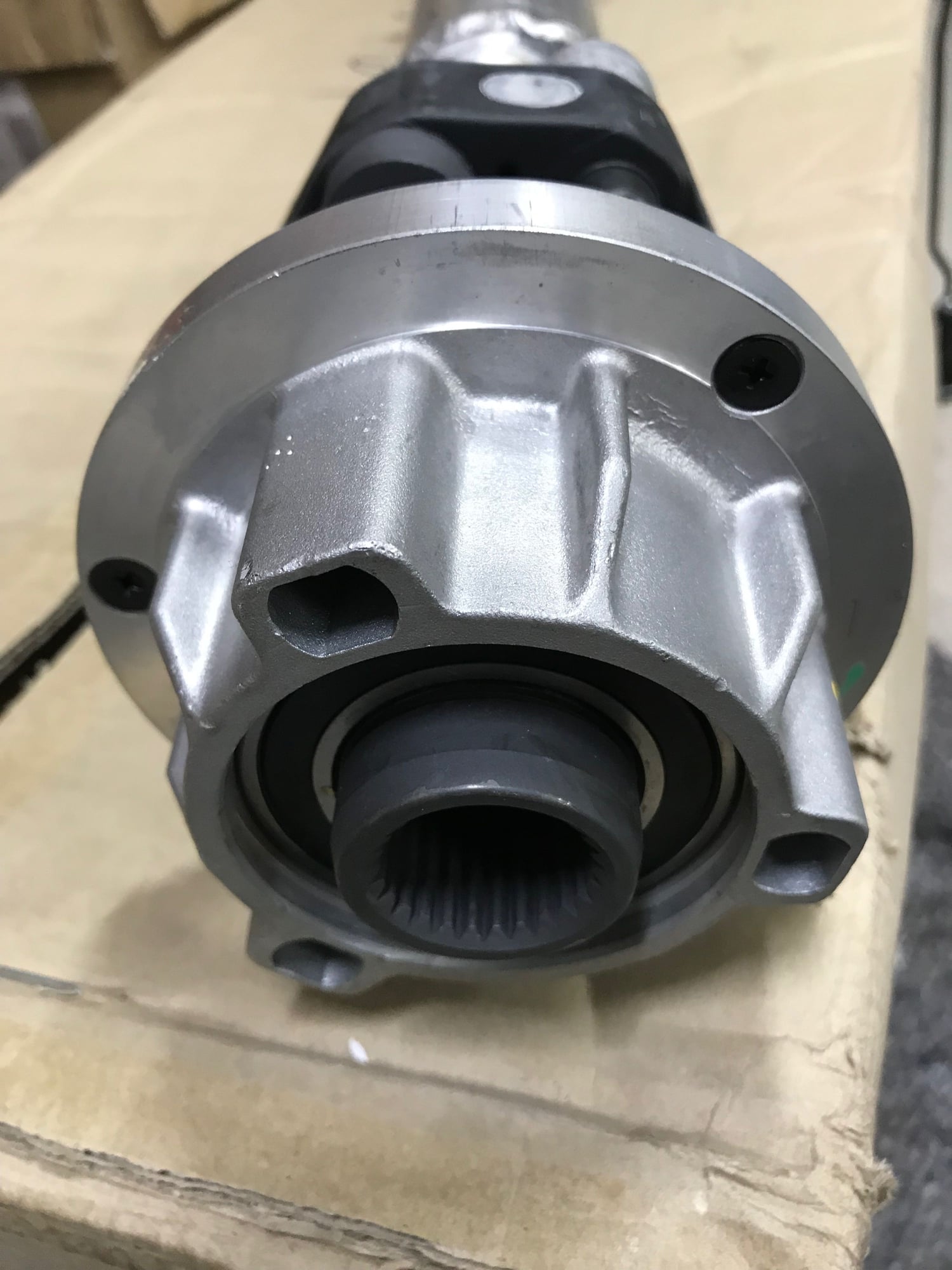
The clutch on the ZO6 is quite big and weighs 2.5 kgs more, it has a steel construction versus the Porsche twin plate which has a lot of alloy in its construction. So the Corvette clutch will have more rotational inertia, the driveshaft similarly has more rotational inertia despite being alloy. There will be no weight saving in the (most likely) carbon torque tube assembly. The only benefit will be a more robust driveline. The other very interesting aspect could well be a safeguard for the transmission. I have heard that the 928 manual transmission can break 5th gear. When I look at the Corvette setup versus the 928's I noticed one very distinct difference. The Corvette has a very strong rear bearing support.
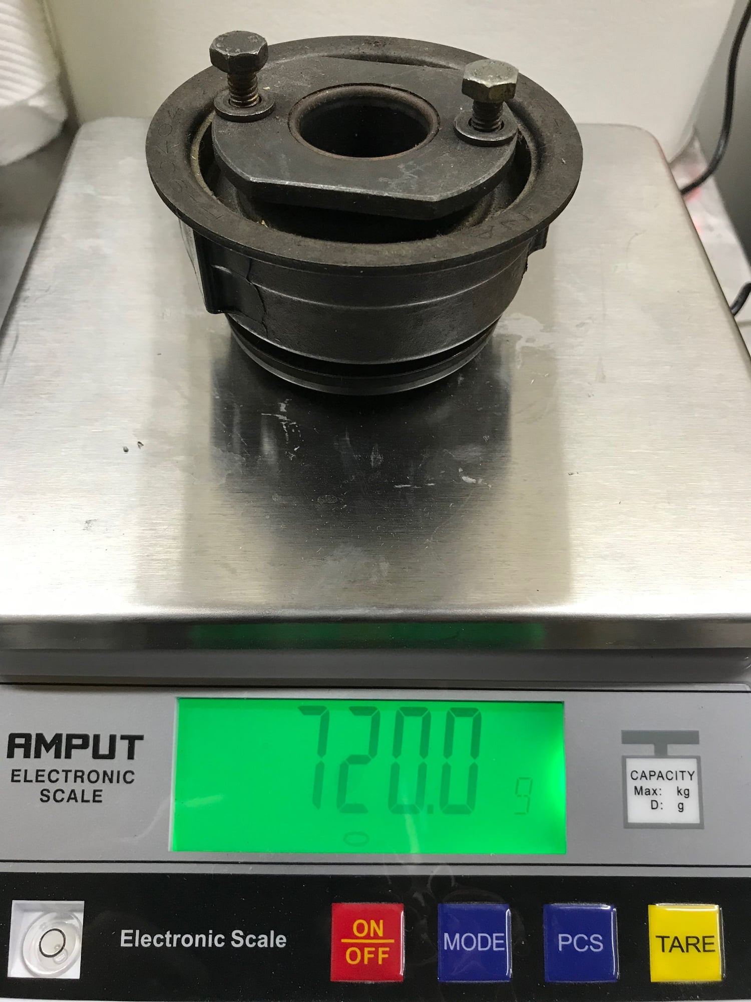
Corvette C7 Rear torque tube bearing assembly
Corvette C7 Rear Tube Coupling
So how might this help the 928 transmission? Well given the 928 driveshaft is so small in diameter, it will have some wind up during hard acceleration and harsh gear changes. This will be made worse by the use of slicks, I wonder what the situation has been with race cars? If I am correct there would be some whip in the driveshaft that loads and fatigues the input shaft into a eventual failure. The GM solution is to have a much stiffer driveshaft and then mount a bearing right at the end of the shaft so that there is no radial loading like that I believe will occur with the 928 setup. So this conversion may well add to the reliability of the 928 drivetrain.
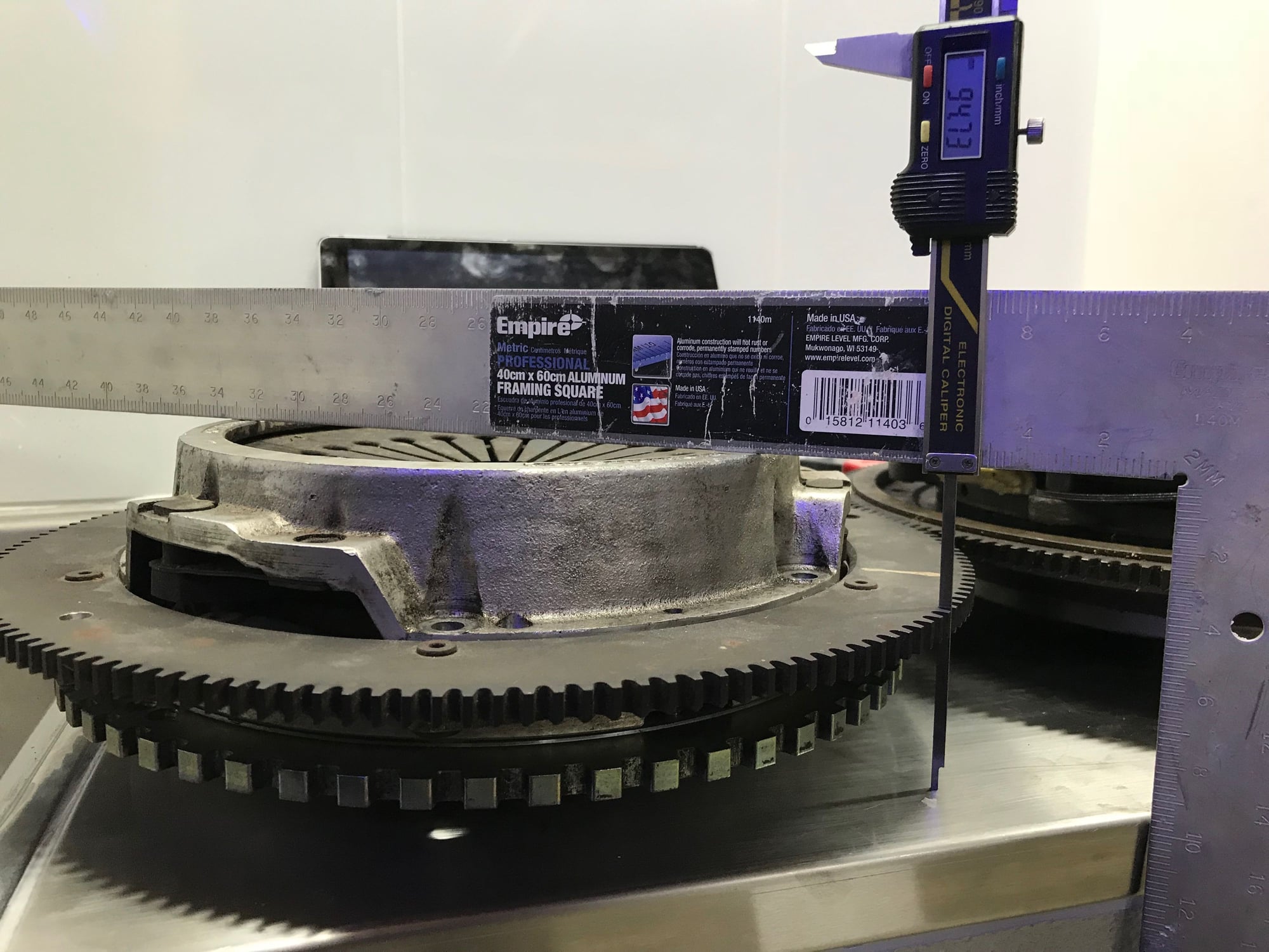
To describe the clutch photos, as there is an issue with getting such a large clutch, it must be compact in design. You can see the height of the stock set up here,
So the height is around 95 mm.
So this photo is the Porsche manual flywheel with the Corvette setup sitting on top of it. I would need to compact the assembly by about 5 mm which should be quite achievable.
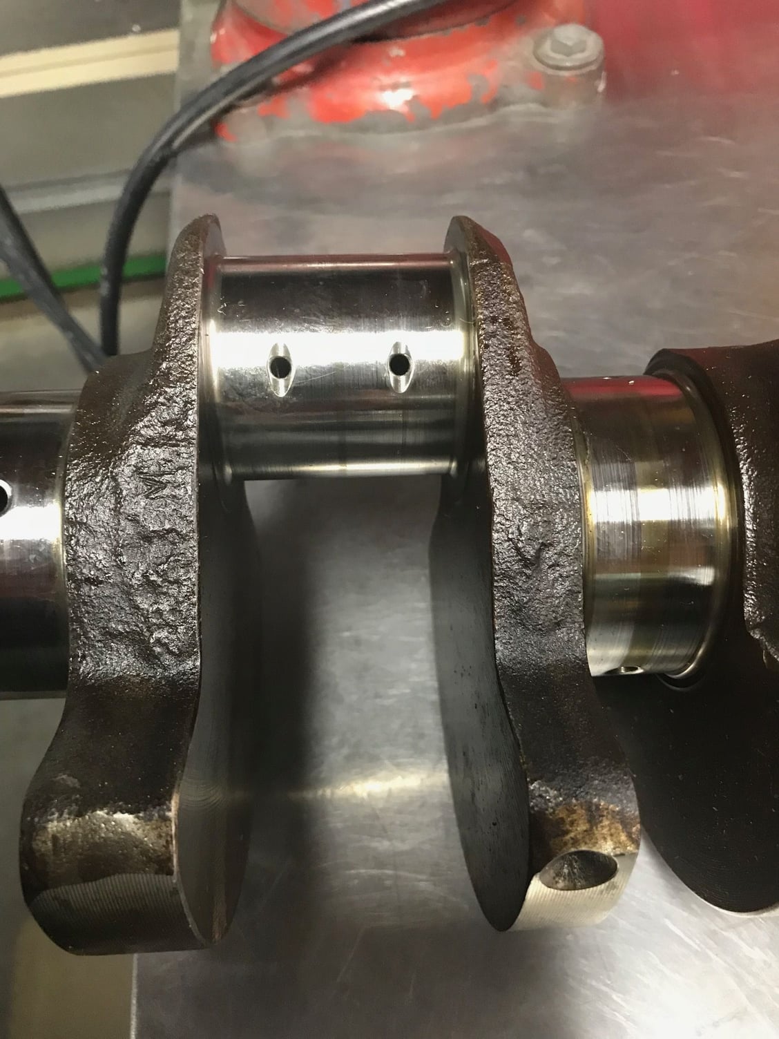
Ok so about to go interstate and taking the crankshaft with me to be roughed in regarding the journal reductions. So to be clearer for those who are not following this that closely, I decided after the Nicasil failed to bond to the bore, I would fit cast iron sleeves and then I decided I would further increase the bore and then I decided.......to offset grind the crank! An idea I was going to do all the way back in 2006🤨
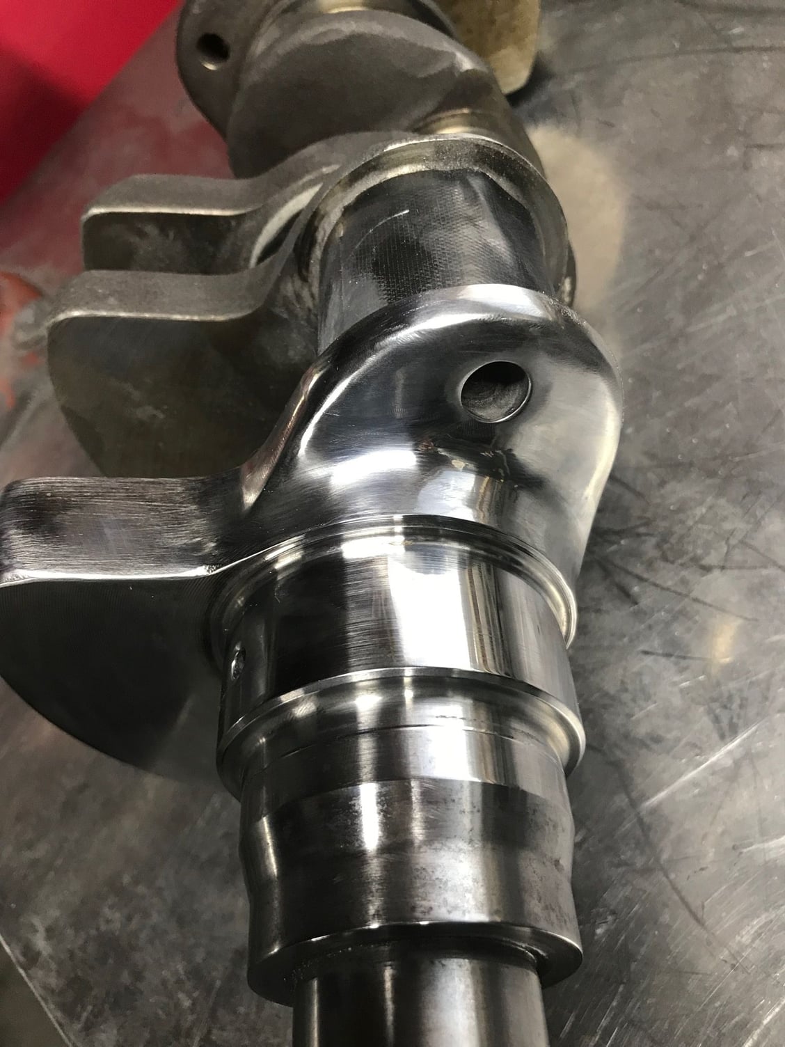
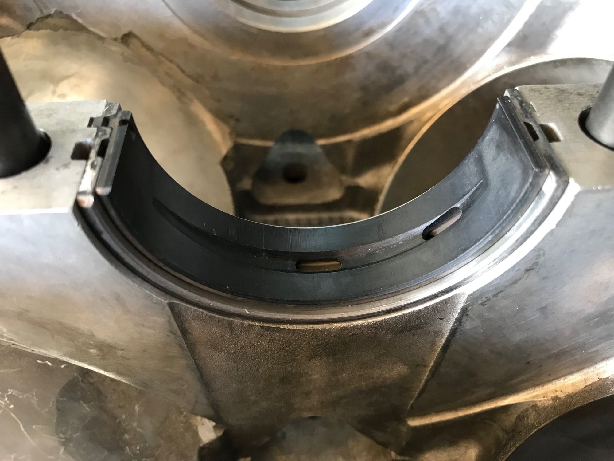
So before dropping the crankshaft off I thought I�d look at tidying it up. There is a fair bit of rough finish on the crank and I intend to super finish the crankshaft after its nitrided. The bobweight for a standard crank is around 2350 to 2390 grams and the new bobweight will be around 1500 grams. This means a fair bit of weight to come of the crank as the other weight reduction is the rod journals going from 52 mm to 48 mm. I�m not sure how much reworking we are going to do. I have set the weight reduction at $750 USD approx and as such we will see what we can get for that. I thought I might take the grinder to the weights and bullnose them and taper the trailing edges. However first of all I thought I better see how hard it was to remove some of the rough forging material and polish it up a bit. The whole shaft will be dedagged and polished. The crankshaft grinder believes he can probably get an extra 3.7 mm of stroke. That will then be 82.6 mm. Four of the five main journals will go to 65 mm with the thrust going 0.25 mm under.
The tunnel falls right in the middle of the tolerance for the LS bearings. I�m going to try and avoid a line bore as I would need to buy new 0.50 mm bearings
and then hone them, however I am reserving this as a back up plan depending on how well the crankshaft measures up insitu. The sleeves may turn up tomorrow, I know they are now local but I leave tomorrow and may miss them by a day. I will get them fitted ASAP and they area a special cast iron btw, very hard and strong but still process by CBN honing. Then I will order my CP pistons. I tell you all, this is a lot of work, to order the pistons I need to make a dummy piston crown and send it to them. For the rings I�m thinking 1 mm top 1 mm 2nd and perhaps a 2 mm oil, we�ll see.
(Jesus, the software that this board runs really sucks hairy *******...)
Greg - is your plan to lighten the crank by cutting the centermost counterweights from one side? That is, to align the counterweight more to line up on the opposite side of the throw? Given that you are reducing the main and rod journal diameters and they this will reduce the crank pin to main journal overlap, I�d consider that. I�d even consider adding some heavy metal to the centermost counterweights on one side to reduce the main bearing loads. I think that reducing those loads will help with both longevity and power if you spin the engine to high rpms.
(Jesus, the software that this board runs really sucks hairy *******...)
Greg - is your plan to lighten the crank by cutting the centermost counterweights from one side? That is, to align the counterweight more to line up on the opposite side of the throw? Given that you are reducing the main and rod journal diameters and this refucing the crank pin to main journal overlap, I�d consider that. I�d even consider adding some heavy metal to the centermost counterweights to reduce the main bearing loads. I think that reducing those loads will help with both longevity and power if you spin the engine to high rpms.
Yes doesn�t the software suck! I have some heavy metal we can use, so good idea, I�m only using that heavy metal to torment the occasional unsuspecting child that visits. (It�s in a matchbox) I will put that to them. Also you may be interested in that I found some strength numbers for our blocks. That is Reynolds 390 and I compared it to A 356 T6. The strength really depends on what heat treat we got. I was thinking about getting a Rockwall test on it to see. Might do that when we fit the sleeves. The cylinder heads were also dropped off at the welder today. I�ll let him take care of the heavy duty welding.
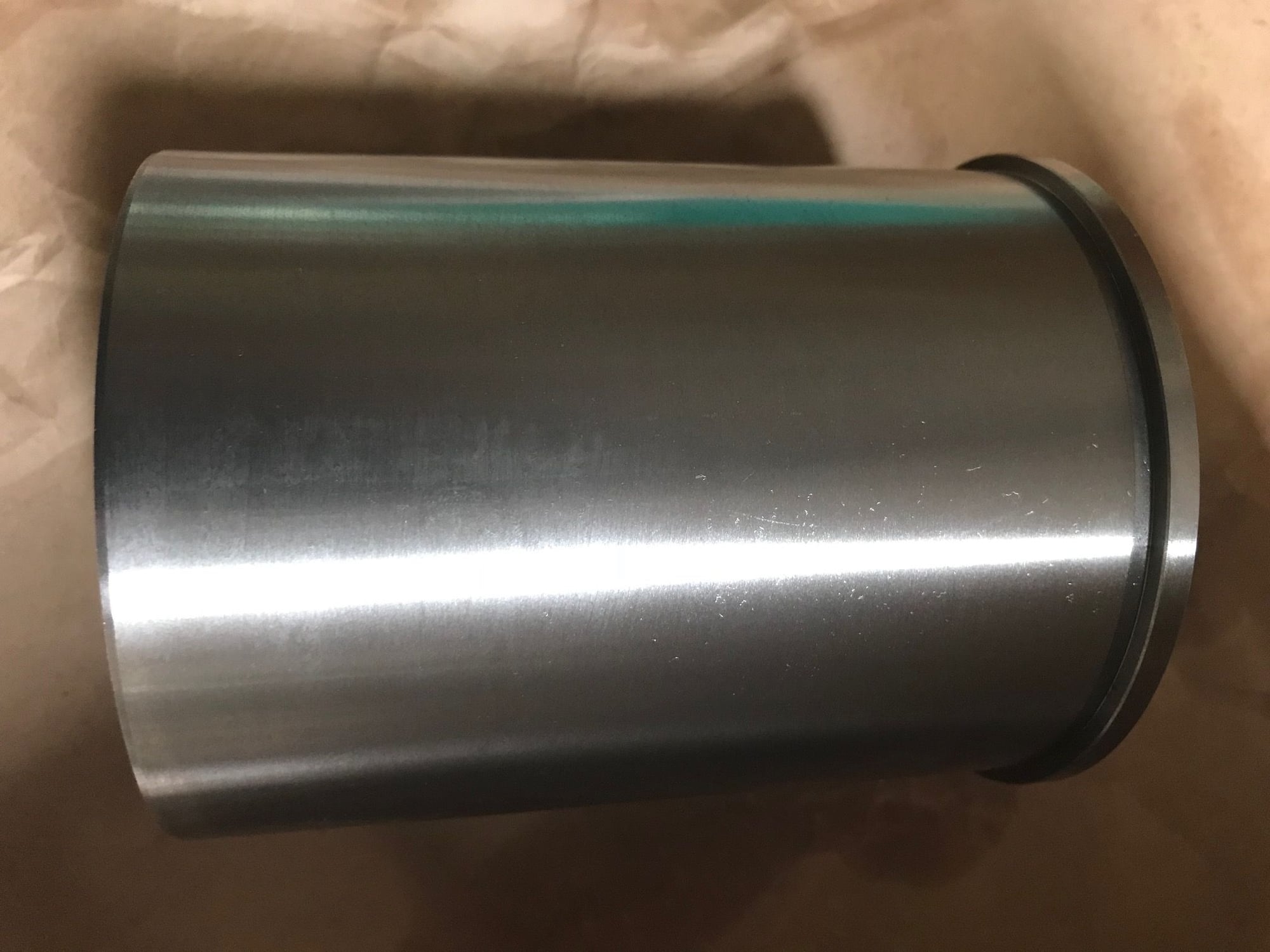
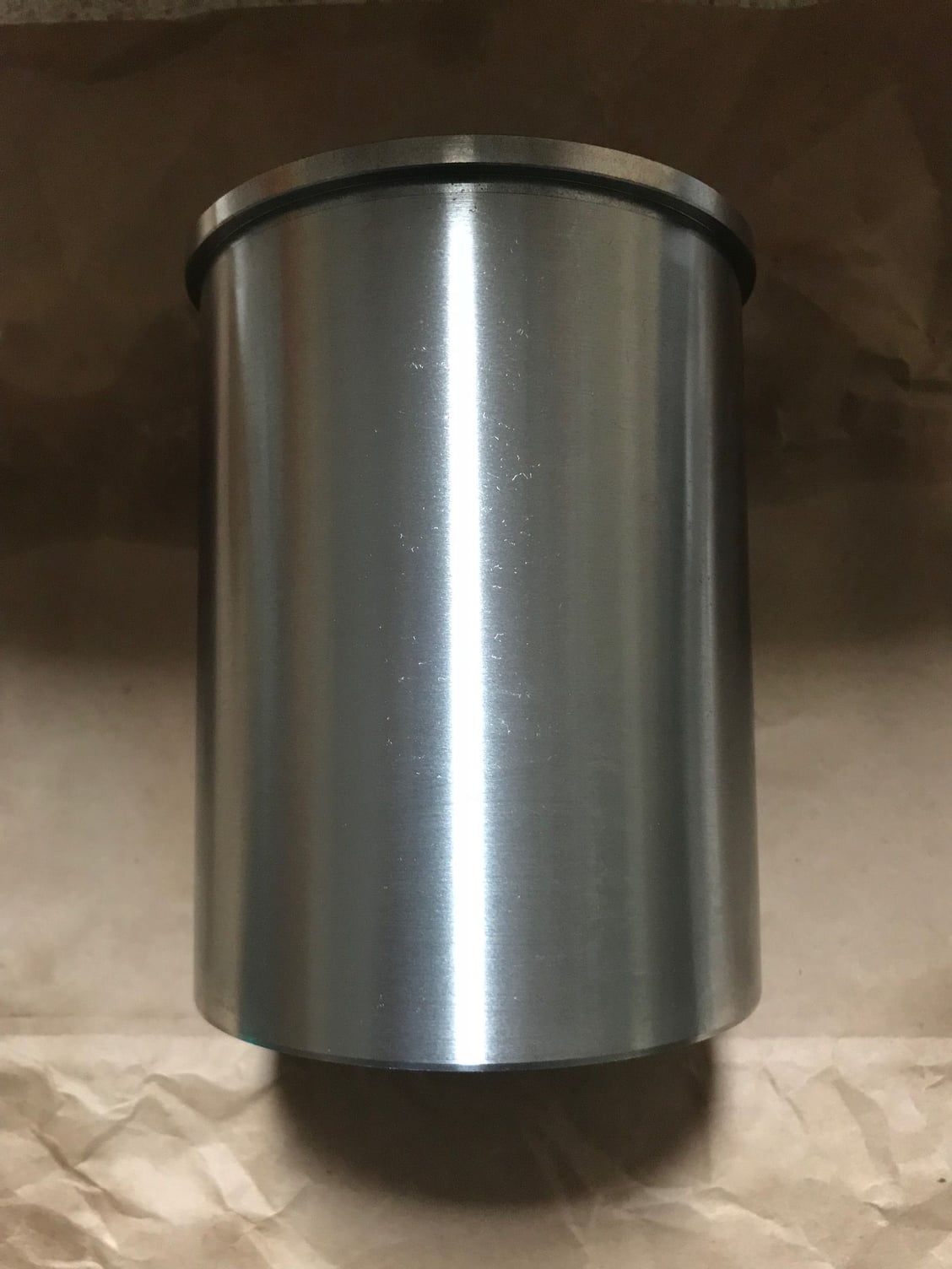
The sleeves turned up today, that is good timing given we�re on a road trip interstate tonight. They look great and weren�t expensive either. I also continued to polish the crankshaft and so far have trimmed 400 grams off it in the form of forging crust. It will be interesting to see what they say regarding the rework. I am taking the heavy metal with me. They have warned me I�m most likely up for another heat treat.
LA Sleeve�s flanged sleeve, same material used in the Top Fueler dragsters.
Made from moly 2000 cast iron with 50,000 psi tensile strength.
Has similar molecular (elements) make up to Nicasil and Sume bore.
The Swedish Steel Company Uddeholm claim their Impax Supreme steel is well suited for the making of cylinder sleeves. I do not know what to say, I have always been using cast iron for sleeves but this particular steel might work. Some have been using it for racing vehicles but it has not prevented engine damage caused by a broken con rod.
�ke http://www.istma-europe.com/istma-wo...er%20steel.pdf
At this point I wish I hadn�t run out of thick rods!
Scope of the work
Nearly there....
The top of the bridge was filed back area is so that the throttle bodies can have the correct angle off the head. Without this, the intake on this cylinder would be adversely effected. The area was welded with a lot of heat to allow it to collapse inwards. This then allowed me to fill the area and as such after it was filed it still had 5 mm wall thickness.
A little bit more progress today, one of the engines being built is a variocam high rpm stroker with 968 heads. One of the many issues is that the 968 ports are much bigger (I need more airflow than a 928 head) and as such the 928 water bridge doesn�t fit. It fits on one side only. It requires a fairly extensive modification. I guess if you had the tools and supplies it would take two full days to do this mod. I�m a bit ham strung so I guess by the time it goes into the polisher it will be three days and half a bottle of argon.
Some pictures to explain
So it is quite visable where the water bridge would bolt down on a 928 head. Notice lots a gaps to be filled
The set screw is recessed and the water routed around the inner clamping bolt.
I didn�t want there to be dags inside the pipe where I was concerned corrosion may lerk.
I had to weld both the inside and outside of the housing.


 11-27-2017, 02:19 AM