
Vacuum repair- No engine start now
 10-30-2013, 03:39 PM
#61
Advanced
Thread Starter
Join Date: Aug 2013
Location: HSV
Posts: 55
Likes: 0
Received 0 Likes
on
0 Posts
I agree... This is great professional help...
In Post 53, could anyone verify if that is a CE from an Automatic car or Manual? John Speake asked me if i had a kickdown relay installed. According to my owners manual, that relay bay is appropriately empty for my 5-Speed...
Update:
Still no start...
Replaced Crank Position Sensor.
Jumpered EZF and LH but still no Noid Light illum.
Tach showing RPM during start bouncing between 1000 and 2000 rpm.
trying to use the "Scope" program and voltage divider to see the pulse and determine if the pulse is "square" enough to fire the EZF and LH.
Anyone do this before could check my wiring and also the equation? I measure 4.2 vdc, not the .5vdc i need...
Any specific terminals that i can test to see if there is any signals to communicate on the 25 or 35 pin terminals?
Thanks all...
 10-30-2013, 04:12 PM
#62
Burning Brakes

Join Date: Mar 2012
Posts: 868
Likes: 0
Received 0 Likes
on
0 Posts
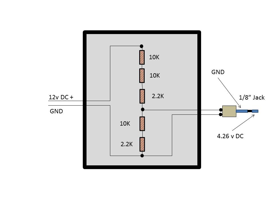
In this circuit I believe Vout = Vin * (R2/R1+R2)
R1 is a series resistance = 10K + 10K + 2.2K = 22.2K
R2 is a series resistance = 10K + 2.2K = 12.2K
Vin = 12v
Vout = 12 * (12.2K / (22.2K + 12.2K))
= 12 * .3546
= 4.25581
I can't see any way for this circuit to produce your expected value of .5vdc
R1 is a series resistance = 10K + 10K + 2.2K = 22.2K
R2 is a series resistance = 10K + 2.2K = 12.2K
Vin = 12v
Vout = 12 * (12.2K / (22.2K + 12.2K))
= 12 * .3546
= 4.25581
I can't see any way for this circuit to produce your expected value of .5vdc
10-30-2013, 04:21 PM
#63
Rennlist Member

I sent my LM-2 to you a few days ago, if you haven't received it yet you should see it today I would think. After you receive it you will need to find a constant power supply to connect it to so you can log during cranking then I'd connect it to the RMP signal and the CPS as I described in my email. Then look at the graphs and see what you have. You will need to down load and install Logworks, and then you will be able to graph your data. There is one file on the SD card which is just the two previously mentioned connections hooked to my car with the car idling. I was going to give you a plot of the cranking signal but my particular power source was wired to shut off during cranking so I couldn't get it to record without getting into my wiring of the power socket. Didn't know when I'd get the chance so thought it better to get it sent down to you.
10-30-2013, 09:11 PM
#67
Advanced
Thread Starter
Join Date: Aug 2013
Location: HSV
Posts: 55
Likes: 0
Received 0 Likes
on
0 Posts
No load test done. Brand new battery. I also have been cranking with a starter/charger on start insuring 13 volts and verified at starter and jump post.
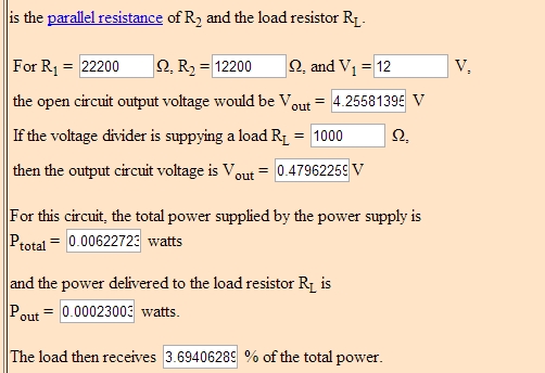
On calculation chart, it shows RL being 0.5 on load. Believe it is right and am going to forge ahead...
Will let all know how the pin out voltages are on crank.
On calculation chart, it shows RL being 0.5 on load. Believe it is right and am going to forge ahead...
Will let all know how the pin out voltages are on crank.
10-31-2013, 01:10 AM
#68
Advanced
Thread Starter
Join Date: Aug 2013
Location: HSV
Posts: 55
Likes: 0
Received 0 Likes
on
0 Posts
No joy again...
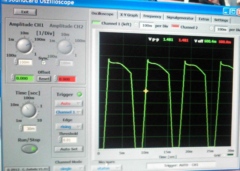
I did learn how to make a "Voltage Divider" for the zillow scope program...
I do not know if it worked as the square wave only showed itself when the ignition was on, no crank. When I cranked it, it was all peaks and compressed, so do not know if it was right. This would be taken on Pin 1 LH2.2. Would i get a different signal on EZF pin 7 ?
So, injectors fire when grounded? That would be pin 13 LH2.2 grounding? where does the 12v to injectors routing or supply originate? I currently have a shunt between the two pins on the injector, no 12v to ground from either pins with both the LH2.2 and EZF connections off.
Greatly appreciate!
10-31-2013, 07:32 AM
#69
Rennlist Member
There shouldn't be any waveform on pin 1 LH with igntion off..... or have you bridged relays ?
Why do you have a "Shunt" between two pins of an injector ? Do you mean a shorting link ?
You MUST remove it as the LH ECU will be damaged as soon as it tries to fire the injectors
Why do you have a "Shunt" between two pins of an injector ? Do you mean a shorting link ?
You MUST remove it as the LH ECU will be damaged as soon as it tries to fire the injectors
10-31-2013, 11:53 AM
#70
Rennlist Member
12 V supply to the injectors comes from pin 87 of the Fuel Pump relay (XX). It does not however go through the FP fuse (#42). This power also goes to the heating element of the O2 sensor. With the LH 25 pin disconnected and the XX relay jumped you should get 12V at pin 13 of the LH connector (provided you have at least 1 injector connected to the harness or a jumper installed at the injector location). Do not connect the LH harness with a jumper of “shunt” connected at any injector locations. Since this power also supplies the O2 heater you can also check for 12 V at the blue wire of the 2 pin O2 connector.
If it where me the first test I would run with the O-scope would be OS+pin to EZF pin 7 and OS-pin to EZF pin 19. Do this with the EZF and LH 25 pin connectors disconnected. This will validate the CPS signal.
Once you have verified you are getting signal from the CPS to the EZF plug I would install the LM-2 Bridge and connect the EZF harness. Connect the LM-2 to RPM EZF pin 16, and logging channel 1 to the CPS EZF pin 7 and 19. Leave the LH harness disconnected at this time. Turn the key on but do not crank. You should have “0” readings for all inputs of the LM-2. If you are getting anything other than “0”, you have an issue. Start logging with the LM-2. Now turn the key to crank, recording the output. You should see an RPM signal consistent with cranking RPM. You will not likely see anything consistent on the CPS display. You will need to download the data to be able to see what is going on there.
Let us know what you get and we’ll go from there.
10-31-2013, 12:47 PM
#71
Advanced
Thread Starter
Join Date: Aug 2013
Location: HSV
Posts: 55
Likes: 0
Received 0 Likes
on
0 Posts
John,
Sorry, bad description... No, there isn't a "shunt" installed, but i was describing a condition where i show continuity between the two pins on the injector when testing with a DVM.
I was able to I believe fire the injectors by grounding Pin 13 LH2.2 as I heard clicking while my head was under the dash. I couldn't see if the Noid Light was firing, but when i used a longer wire connected to pin 13 and tried to ground out while at the engine, nothing happened, and then i couldn't replicate again as i did previously. This is when i removed the Noid Light and measured continuity across the injector pins. Very frustrating... Pin 7 on EZF is the CPS signal? Should read 4 vac when crank or square wave on scope?
Simon,
Yes, home run with receiving late yesterday LM2. I have wired a dedicated fused cigar socket to power the LM2 for tonights foray into the impossible it seems. I will run tests as you describe.
I was asking where the 12vdc came from as the injector lead (red/white ) did not have voltage nor the brown. If this was "grounded", shouldn't a fuse be burned out as the 12vdc would have to be going straight through and burn out its source?
I have not installed the FP relay as i still have the FP regulator off making it easier to muck about back there. This also creates an unknown as I do not know if the LH2.2 is turning on the fuel pump relay "proving" that logic circuitry during crank... I have done all of this testing with both the MAF disconnected and connected. Should i install or maybe jumper the MAF ?
This leads up to a future branch of this discussion not crossed yet, if there is a catastrophic failure somewhere in the wiring harness, could i just rewire the injector loom? Two leads from EZF (pin 1 and 13) and then ground back to MPviii and MPix all in parallel ?
10-31-2013, 12:57 PM
#72
Rennlist Member
The Engine will run w/o the MAF, here is a video of what the CPS sig should look like w/ the engine running, I guess I'm missing something if you had what is pictured (square wave) on your PC screen w/o the engine running or at the least cranking.
Dave
Dave
10-31-2013, 01:57 PM
#73
Rennlist Member
I was able to I believe fire the injectors by grounding Pin 13 LH2.2 as I heard clicking while my head was under the dash. I couldn't see if the Noid Light was firing, but when i used a longer wire connected to pin 13 and tried to ground out while at the engine, nothing happened, and then i couldn't replicate again as i did previously. This is when i removed the Noid Light and measured continuity across the injector pins. Very frustrating... Pin 7 on EZF is the CPS signal? Should read 4 vac when crank or square wave on scope?
I have not installed the FP relay as i still have the FP regulator off making it easier to muck about back there. This also creates an unknown as I do not know if the LH2.2 is turning on the fuel pump relay "proving" that logic circuitry during crank... I have done all of this testing with both the MAF disconnected and connected. Should i install or maybe jumper the MAF ?
This is why I would like him to get the LM-2 connected to the EZF to confirm that he isn�t getting an RPM signal without engine rotation. When I had my issues, I was getting a 450 RPM signal from the EZF with the key on and engine not turning. I had some bad solder joints in my EZF causing the rogue signal. After rewetting them everything has been fine since, but we need to know what he�s got.