
Headlight Height Adjuster Overhaul
 10-02-2013, 03:03 PM
#1
Intermediate
Thread Starter
The headlight height adjusting system on my '85 928S hasn't worked for quite some time, and it is one of the things that has been on the list of things to repair during my mini restoration.
I have managed to repair the system and here's how it was done:
Hydraulic Headlight Height Adjustment System Overhaul
Euro spec 928s are fitted with a headlight height adjustment system, which can be adjusted down when the car is loaded so that the headlights do not shine into the oncoming traffic. The headlights are adjusted down by turning the **** next to the driver�s seat from the �0� position to either the �1�, �2� or �3�, with position �3� being the lowest.
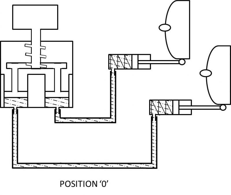
It is a basic hydraulic system, with a hydraulic rotary switch activating hydraulic actuators below the headlights, tilting them up or down.
In Position �0�, the adjusting **** has pushed the pistons down to their lowest level via a screw thread. The hydraulic fluid then pushes the pistons in the actuators forward, which are connected to the headlights, raising the beam up. The springs in the actuators are now under tension.
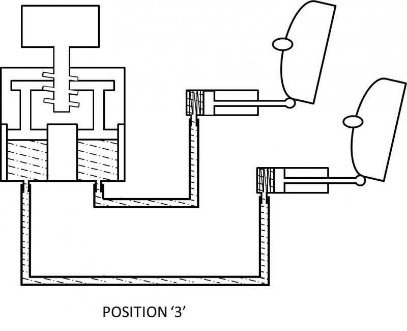
By turning the **** to Position �3�, the pistons move up the screw thread and the springs in the actuators contract and pull the headlights down, pushing the fluid back into the hydraulic switch.
The fluid used seems to be like anti-freeze, or a fluid of the same viscosity and over many years this fluid evaporates. It can also be that the hydraulic lines become brittle and break, but evaporation is more likely. Once the fluid evaporates, the system is filled with air and because the springs in the actuators are under tension, the headlights are pulled back and the beam now only shines a few meters in front of the car.
Overhauling the system is not difficult � it�s a fairly straight forward step-by-step process:
1) Jack the car up at the front and remove the wheels.
2) Remove the inner wheel arch covers.
3) Turn the headlights on so that they pop up and switch off the ignition so that they remain in the upright position.
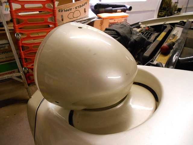
4) Take off the headlight covers by removing the three mounting screws.
5) Loosen the headlight unit by removing the two nuts and washers on either side.
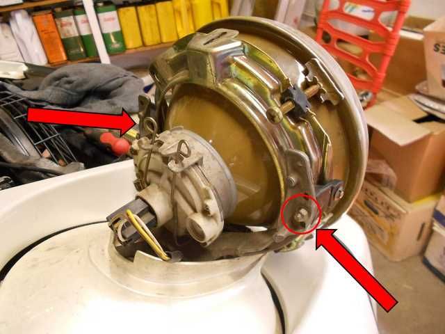
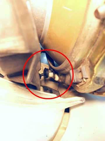
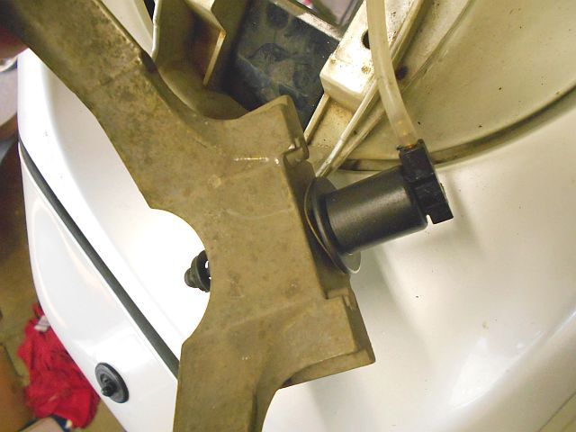
The headlight is attached to the hydraulic actuator at the bottom of the headlight unit. The piston has a ball at the end which fits into a plastic socket on the headlight unit, and secured in place with a black plastic clip. Remove this black plastic clip carefully and pull the headlight unit away, releasing the ball from the socket. TAKE NOTE THAT THIS SHOULD BE DONE WITH GREAT CARE, AS THESE PLASTIC FITTINGS ARE INVARIABLY BRITTLE WITH AGE.
6) The yoke that supports the headlight assembly also supports the hydraulic actuator.
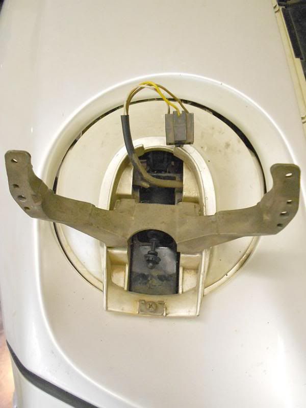
To remove the hydraulic actuator, the yoke must be removed from the headlight base, by removing the two Allen cap screws underneath. This is accessed from inside the fender. Loosen the small plate that holds the hydraulic line in place at the bottom of the headlight base so that the yoke, actuator and hydraulic line can be pulled away from the headlight base.
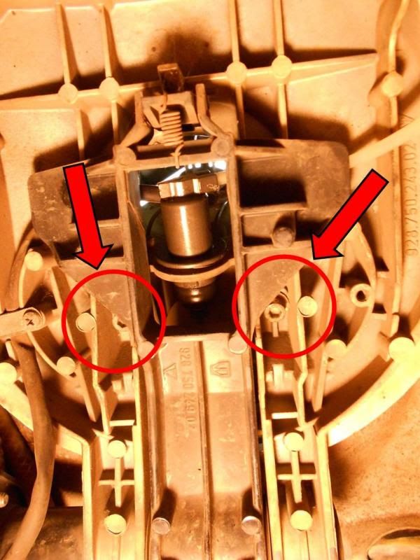
When removing the yoke from the base plate, take care to remove the captive nuts that secure the yoke, as these are loose and will fall off and disappear.
7) Push the hydraulic actuator against the yoke and compress the spring washer. Twist the actuator left or right to align the lugs with the spaces in the yoke and remove the yoke.
8) Cut the hydraulic line close to the nipple of the actuator with a craft knife and mount the actuator in a jig so that the piston is pulled out to the maximum.
A jig can be easily made from 32mm flat bar according the the following dimensions:
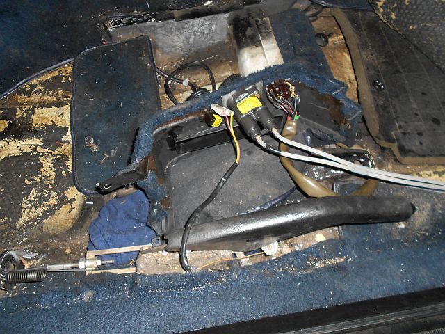
9) Remove the screws that secure the handbrake and switch cover in place, and pull the cover over the handbrake to access the hydraulic rotary switch. Cut both the hydraulic lines off the nipples at the bottom of the switch, and determine which line runs to which headlight by blowing air into the line from the headlight side. Mark which line is which side.
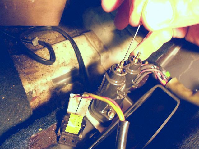
10) Rotate the switch into the Position �3� and then turn the switch upside down so that it stands vertically. Push the pistons inside the switch to the bottom of the cylinder with a piece of wire � the system is now ready to be filled with fluid.
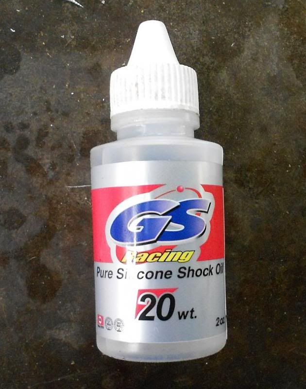
11) The original fluid may have been anti-freeze, but silicon oil is an alternative. It comes in various viscosities and is used in shock absorbers on radio controlled cars � choose the oil with the lowest viscosity, which is 20wt. The silicon oil is thicker than the original fluid and the result is that the headlights will take a little longer to dip.
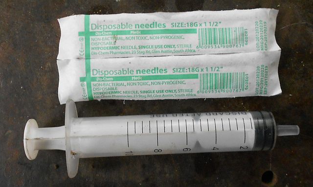
12) Use a syringe (10ml) and size 18G x 1 �� needles to fill the system with silicon oil.
13) Start by injecting oil into the rotary switch until the cylinder is filled and fluid runs out. Keep injecting fluid as the needle is pulled from the nipple to ensure that the cylinder is filled entirely.
14) Next, inject fluid into the hydraulic line from the headlight side until the line is full and runs cleanly from the other side without air bubbles. Use a tin or plastic dish to catch the fluid. Once the hydraulic line is full, push it onto the nipple of the switch.
15) With the actuator mounted in the jig, inject oil into the actuator until full.
16) Turn the switch into Position �0� � by doing this fluid is pushed through the hydraulic line to eliminate any air pockets that may be close to the headlight end of the hydraulic line. Push the hydraulic line onto the filled actuator, and remove the actuator from the jig. The system is now under pressure, so wipe away any excess fluid and check for leaks in the system.
17) Follow the same procedure to fill the other hydraulic line.
18) To reassemble, turn the switch to Position �3� and refit the actuator to the yoke. Then reconnect the piston of the actuator to the headlight unit, replace the black plastic clip and secure the headlight unit to the yoke with the two nuts and washers.
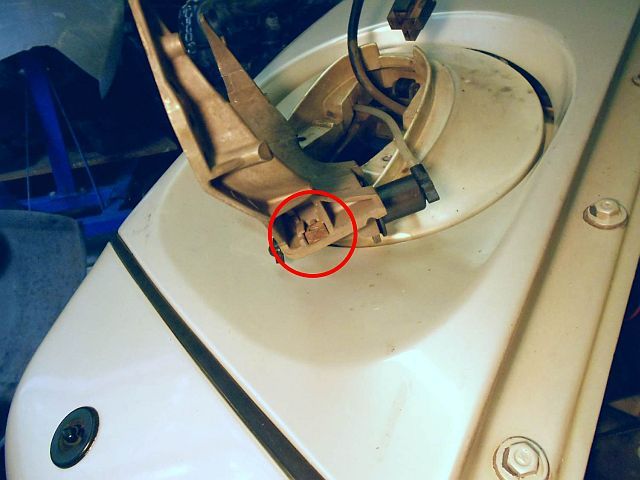
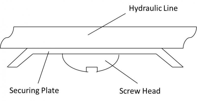
19) Replace the two square captive nuts into the sides of the yoke and secure the yoke to the headlight base from the bottom with the two Allen cap screws. Secure the hydraulic line into place at the bottom of the headlight base with the small plate and screw. If the plate has been completely removed, ensure that it is refitted so that the edges of the plate are away from the hydraulic line, otherwise the edges of the plate will cut the hydraulic line:
20) Switch on the headlights, rotate the switch between Position �0� and Position �3�and check that the beam drops and lifts accordingly.
I have managed to repair the system and here's how it was done:
Hydraulic Headlight Height Adjustment System Overhaul
Euro spec 928s are fitted with a headlight height adjustment system, which can be adjusted down when the car is loaded so that the headlights do not shine into the oncoming traffic. The headlights are adjusted down by turning the **** next to the driver�s seat from the �0� position to either the �1�, �2� or �3�, with position �3� being the lowest.
It is a basic hydraulic system, with a hydraulic rotary switch activating hydraulic actuators below the headlights, tilting them up or down.
In Position �0�, the adjusting **** has pushed the pistons down to their lowest level via a screw thread. The hydraulic fluid then pushes the pistons in the actuators forward, which are connected to the headlights, raising the beam up. The springs in the actuators are now under tension.

By turning the **** to Position �3�, the pistons move up the screw thread and the springs in the actuators contract and pull the headlights down, pushing the fluid back into the hydraulic switch.

The fluid used seems to be like anti-freeze, or a fluid of the same viscosity and over many years this fluid evaporates. It can also be that the hydraulic lines become brittle and break, but evaporation is more likely. Once the fluid evaporates, the system is filled with air and because the springs in the actuators are under tension, the headlights are pulled back and the beam now only shines a few meters in front of the car.
Overhauling the system is not difficult � it�s a fairly straight forward step-by-step process:
1) Jack the car up at the front and remove the wheels.
2) Remove the inner wheel arch covers.
3) Turn the headlights on so that they pop up and switch off the ignition so that they remain in the upright position.

4) Take off the headlight covers by removing the three mounting screws.
5) Loosen the headlight unit by removing the two nuts and washers on either side.

The headlight is attached to the hydraulic actuator at the bottom of the headlight unit. The piston has a ball at the end which fits into a plastic socket on the headlight unit, and secured in place with a black plastic clip. Remove this black plastic clip carefully and pull the headlight unit away, releasing the ball from the socket. TAKE NOTE THAT THIS SHOULD BE DONE WITH GREAT CARE, AS THESE PLASTIC FITTINGS ARE INVARIABLY BRITTLE WITH AGE.

6) The yoke that supports the headlight assembly also supports the hydraulic actuator.

To remove the hydraulic actuator, the yoke must be removed from the headlight base, by removing the two Allen cap screws underneath. This is accessed from inside the fender. Loosen the small plate that holds the hydraulic line in place at the bottom of the headlight base so that the yoke, actuator and hydraulic line can be pulled away from the headlight base.

When removing the yoke from the base plate, take care to remove the captive nuts that secure the yoke, as these are loose and will fall off and disappear.

7) Push the hydraulic actuator against the yoke and compress the spring washer. Twist the actuator left or right to align the lugs with the spaces in the yoke and remove the yoke.

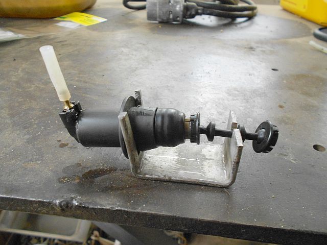
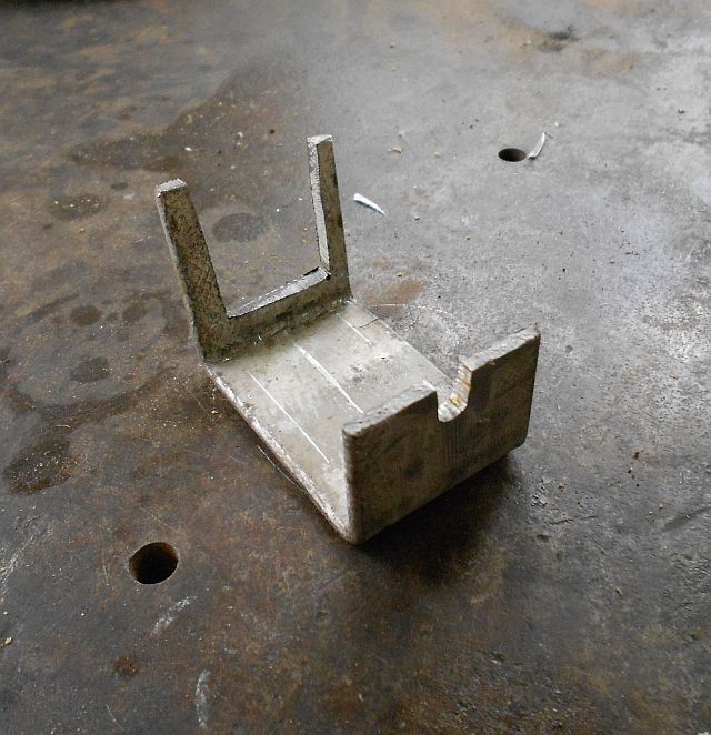
8) Cut the hydraulic line close to the nipple of the actuator with a craft knife and mount the actuator in a jig so that the piston is pulled out to the maximum.

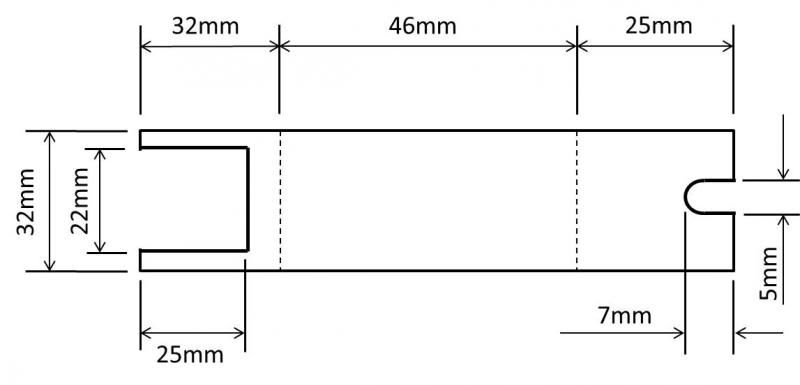
A jig can be easily made from 32mm flat bar according the the following dimensions:


9) Remove the screws that secure the handbrake and switch cover in place, and pull the cover over the handbrake to access the hydraulic rotary switch. Cut both the hydraulic lines off the nipples at the bottom of the switch, and determine which line runs to which headlight by blowing air into the line from the headlight side. Mark which line is which side.

10) Rotate the switch into the Position �3� and then turn the switch upside down so that it stands vertically. Push the pistons inside the switch to the bottom of the cylinder with a piece of wire � the system is now ready to be filled with fluid.

11) The original fluid may have been anti-freeze, but silicon oil is an alternative. It comes in various viscosities and is used in shock absorbers on radio controlled cars � choose the oil with the lowest viscosity, which is 20wt. The silicon oil is thicker than the original fluid and the result is that the headlights will take a little longer to dip.

12) Use a syringe (10ml) and size 18G x 1 �� needles to fill the system with silicon oil.

13) Start by injecting oil into the rotary switch until the cylinder is filled and fluid runs out. Keep injecting fluid as the needle is pulled from the nipple to ensure that the cylinder is filled entirely.
14) Next, inject fluid into the hydraulic line from the headlight side until the line is full and runs cleanly from the other side without air bubbles. Use a tin or plastic dish to catch the fluid. Once the hydraulic line is full, push it onto the nipple of the switch.
15) With the actuator mounted in the jig, inject oil into the actuator until full.
16) Turn the switch into Position �0� � by doing this fluid is pushed through the hydraulic line to eliminate any air pockets that may be close to the headlight end of the hydraulic line. Push the hydraulic line onto the filled actuator, and remove the actuator from the jig. The system is now under pressure, so wipe away any excess fluid and check for leaks in the system.
17) Follow the same procedure to fill the other hydraulic line.
18) To reassemble, turn the switch to Position �3� and refit the actuator to the yoke. Then reconnect the piston of the actuator to the headlight unit, replace the black plastic clip and secure the headlight unit to the yoke with the two nuts and washers.
19) Replace the two square captive nuts into the sides of the yoke and secure the yoke to the headlight base from the bottom with the two Allen cap screws. Secure the hydraulic line into place at the bottom of the headlight base with the small plate and screw. If the plate has been completely removed, ensure that it is refitted so that the edges of the plate are away from the hydraulic line, otherwise the edges of the plate will cut the hydraulic line:

20) Switch on the headlights, rotate the switch between Position �0� and Position �3�and check that the beam drops and lifts accordingly.
 10-02-2013, 03:32 PM
#2

That's a good write up, thanks for sharing.
10-02-2013, 03:50 PM
#4
Drifting
Excellent
Never seen such a well illustrated procedure for the hydraulic adjusters. Wish I'd had it when I owned 88 MY S4 (have 91 MY S4 now with electric adjusters) which had the traditional non-working adjusters.
So you cut the lines to actuators as they can't be filled via the nipple? And then is there enough slack in line to re-attach the shorter line to actuator?
10-02-2013, 04:05 PM
#5
Intermediate
Thread Starter
Porsche have been generous in supplying a long hydraulic line, and you're really just losing about 2cm in total.
10-02-2013, 08:54 PM
#7
Electron Wrangler
Lifetime Rennlist
Member
Lifetime Rennlist
Member
Its a very nice fix you did - but I think its still a flawwed system since most seem to leak, crack etc.
I don't see how a sealed system just evaporates - but its possible there is some long term chemical migration through the tubing materials that affects behaviour
Seems very very few have stood the test of time...
The later electrical system is much more reliable.
Alan
I don't see how a sealed system just evaporates - but its possible there is some long term chemical migration through the tubing materials that affects behaviour
Seems very very few have stood the test of time...
The later electrical system is much more reliable.
Alan
Trending Topics
10-03-2013, 05:25 AM
#9
Intermediate
Thread Starter
10-03-2013, 10:27 AM
#10
Nordschleife Master
Your thread is the first one I've seen that says anything other than: "This system is NOT fixable. If it's broken it will never work again."
09-29-2014, 06:27 PM
#11
Track Day
Thank you Grant for an excellent write-up. Every 928 I tried before I bought my current -89 GT had a faulty headlight adjuster, and every owner said it wasn't fixable.
I'm just doing this procedure now, and things have forked out perfectly until I was going to fill the actuators. When fully extended, I could hardly get any oil into them, and when I released the piston just a teeny drop of oil escaped. The actuator arm seem to move freely, but after repeated attempts, I just can't seem to get any oil into them
Any ideas?
Another thing: The lines are extremely hard, so it is next to impossible to push the line onto the fragile little brass nipple again. I bored the line with a 2.5mm (.1") drill bit on all ends, and even then I could only get the line half way in. Hope they won't leak...
Arnljot
1989 GT
The following users liked this post:
jhalsey (08-12-2023)
09-30-2014, 10:42 PM
#12
Race Car
Wow, another legend of "they never work/can't be fixed" bites the dust!
I ordered a lot of the adjuster parts and tried to activate my system on my Euro, but with no long-term solution.
Great addition, thanks, rated!
I ordered a lot of the adjuster parts and tried to activate my system on my Euro, but with no long-term solution.
Great addition, thanks, rated!
10-01-2014, 02:19 PM
#13
Electron Wrangler
Lifetime Rennlist
Member
Lifetime Rennlist
Member
...To remove the hydraulic actuator, the yoke must be removed from the headlight base, by removing the two Allen cap screws underneath. This is accessed from inside the fender. Loosen the small plate that holds the hydraulic line in place at the bottom of the headlight base so that the yoke, actuator and hydraulic line can be pulled away from the headlight base.
Alan
 10-01-2014, 06:10 PM
#15
Rennlist Member
nzpaul,
I had one sitting around my desk at home for ages in the hope of measuring it up and getting some printed - can't seem to find it ATM. Would also need the cap that snaps over it to hold it closed. I was going to beef up the unit a bit to help with strenght - just havn't got around to it yet.....
Myles